
Abstract
In recent years, mass production of nanofiber has attracted attention of many researchers. Needleless electrospinning technology has been studied and developed to fabricate high-yield nanofibers, which could overcome the shortages of traditional single electrospinning apparatus, such as low efficiency, uneven nanofiber membrane, and difficulty in cleaning single needle. In this study, a novel needleless electrospinning apparatus was used to produce high-quality nanofiber membrane in terms of the features of small nanofiber diameter and narrow diameter distribution. Multiple jets were formed on the edge of the needleless electrospinning spinneret. The number of jets had a significant increase trend with the increase of the applied voltage. Wide-width nanofiber membrane could be fabricated by using this needleless electrospinning setup. This study also investigates the effects of process parameters on surface morphology, stress–strain, pore diameter, and filtration property of nanofiber membrane. This needleless electrospinning apparatus is suitable for industrialization production of nanofiber membrane.
Introduction
Electrospinning is one of the effective techniques to produce nanofiber materials because of its simplicity, convenience, and applicability. Nanofiber has many specific advantages, such as high specific surface area, quantum size effect, and high porosity [1,2]. Electrospinning nanofibers have huge potential application values in various fields, such as filter materials [3–6], sensors [7], tissue engineering scaffold materials [8–12], and wound dressing [13,14].
Conventional needle electrospinning apparatus reduced the throughput of nanofiber and limited the development of electrospinning technology. Numerous efforts have thus concentrated on improving the productivity of the electrospinning technique. Yarin and Zussman [15] first proposed needleless electrospinning concept to fabricate nanofiber in 2004. The steady vertical spikes could be produced on interlayer interface because of the two layer system of both a ferromagnetic and a polymer solution. Later on, more researchers began to focus on needleless electrospinning technology, because multiple jets could be produced to improve the productivity of nanofiber enormously. Air pressure was used to produce multiple bubbles in polymer solution and presented the bubble electrospinning for mass production of nanofibers [16–19]. Jirsak et al. [20] used roller electrostatic spinneret to prepare nanofibers and investigated the effect of different fiber diameters on filtration efficiency and pressure drop. Tang et al. [21] proposed splashing needleless electrospinning apparatus to fabricate nanofibers. The production of nanofibers was enhanced by 24–45 times compared with a single-needle system. Many different kinds and shapes of needleless spinnerets were designed, including cylinder and disk nozzles [22,23], disc and ball [24], spiral coil [25], toothed wheel [26], mace shape [27], tube with an embedded wire loop [28], annular [29], rotating ring [30,31], and sprocket wheel disk spinneret [32]. Investigating the morphology, diameter, and productivity of nanofiber provided the comprehensive references for further research on the needleless electrospinning technology. Lu et al. [33] introduced super-high throughput needleless electrospinning apparatus, which used a rotary cone as spinneret to produce nanofiber. A needleless electrospinning setup named needleless twisted wire electrospinning was developed to produce nanofibers [34]. Jiang et al. [35–38] presented one-stepped pyramid-shaped spinneret to prepare high-throughput nanofibers and core-shell nanofibers. Ng and Supaphol [39] developed rotating-disk electrospinning system to fabricate nanofiber and investigated the production rate, fiber size distribution, and morphology of the nanofiber mats.
Based on above facts, currently, many research reports focused on designing needleless electrospinning spinnerets and studying the diameter and productivity of nanofibers. However, only few reports are about air filtration of nanofibers membrane with needleless electrospinning spinneret. As for air filtration nanofiber membrane, on the one hand, the fineness uniformity of nanofiber should be considered. On the other hand, the stress–strain also significantly influenced the filtration property of nanofiber membrane. The new needleless electrospinning apparatus design needs to meet the demands as mentioned above. In this study, we used the novel needleless electrospinning apparatus to massively produce high quality and thickness uniformity of nanofiber membrane, which could be used for air filtration. Effects of different process parameters on the surface morphology, stress–strain, pore diameter, and filtration property of nanofiber membrane have been studied. This approach has a great potential on the industrialization production and application of high-quality nanofiber membrane.
Experimental
Materials
Polyacrylonitrile (PAN, MW = 75,000 g/mol) was purchased from Shanghai Chemical Fibers Institute. N, N-Dimethylformamide (DMF) was purchased from Shanghai Lingfeng Chemical Reagent Co. Ltd. The PAN powder was dried at 80°C in vacuum for 12 h then dissolved in DMF to prepare spinning solution with concentrations of 10, 12, and 14 wt%. Prepared solution was stirred magnetically overnight until they became homogeneous solution.
Needleless electrospinning setup
The novel needleless electrospinning apparatus comprised a metal dish spinneret, solution control pump, rotating collector system, DC high voltage power supply, spinneret base, and a moving platform. Figure 1(a) shows the schematic diagram of the needleless electrospinning setup. There was a small hole in the center of spinneret, one end of the insulating tube was connected with the spinneret, and another was inserted in polymer solution. The control pump was installed in the middle of the insulating tube. The solution could be transported to the spinneret through the control pump. The PAN solution was stored in metal dish until the edge of solution reached a certain radian. The solution was charged with a high-voltage power supply by connecting a position electrode with the metal dish spinneret. The solution flow rate could be adjusted with the control pump. The spinneret was put on the spinneret base, and the spinneret base was fixed on the moving platform. The moving platform ensured the thickness uniformity of nanofiber membrane. Figure 1(b) shows the physical map of the needleless electrospinning setup. The novel needleless electrospinning apparatus was placed in the sealed box for reducing the influence of the outside ambient on the process of electrospinning. Temperature and humidity control system was installed in the sealed box. Temperature and humidity could be adjusted by changing values in touch screen control plate. The image of multiple jets is shown in Figure 1(c); we could see that multiple jets were formed at the edge of the metal dish spinneret. Figure 1(d) shows the outside view of nanofiber membrane. Wide-width nanofiber membrane could be fabricated by using this needleless electrospinning setup. In the process of needleless electrospinning, we controlled that the temperature was 22°C and the humidity was 40%.
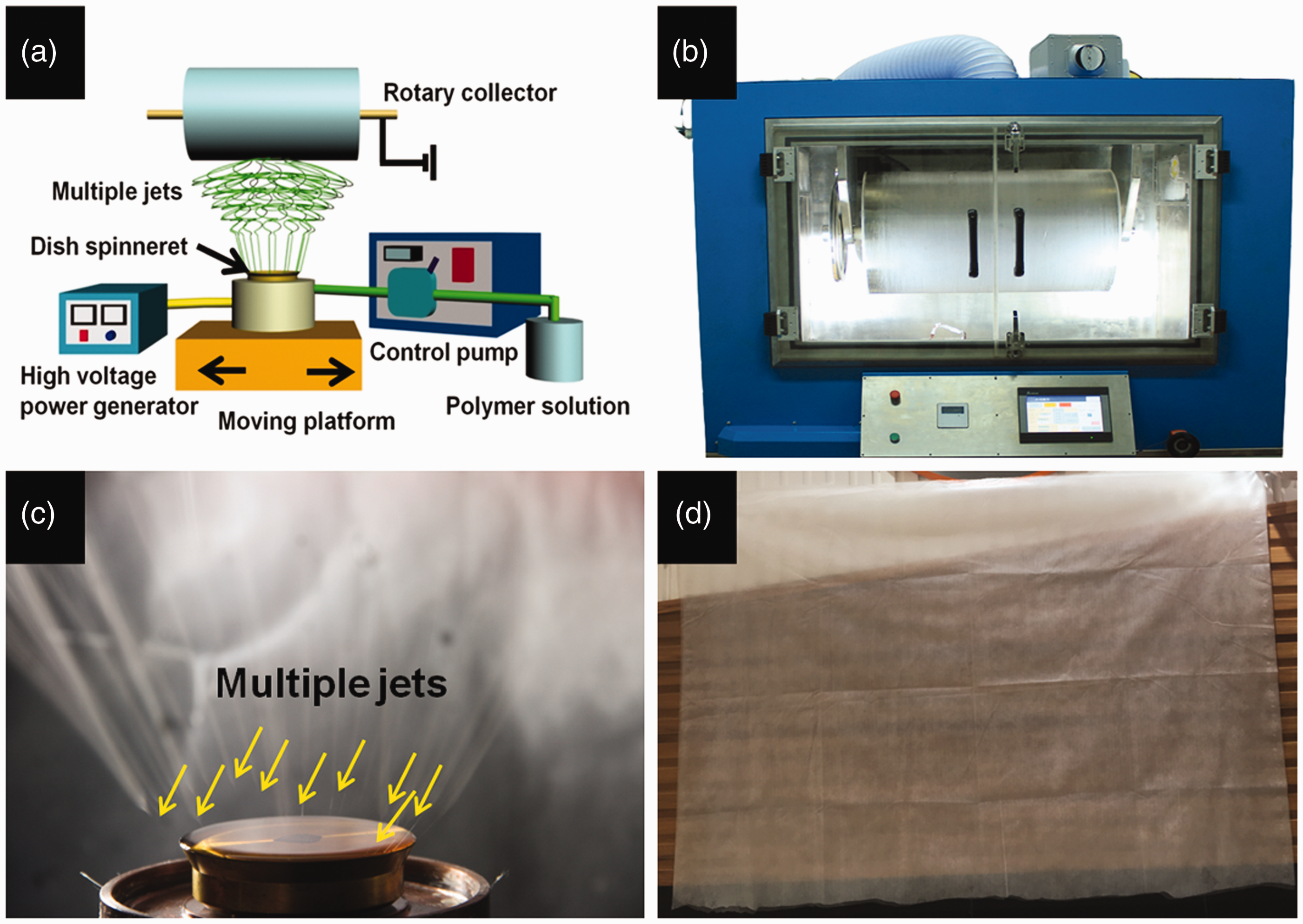
Schematic diagram (a) and physical map (b) of needleless electrospinning setup; (c) the image of multiple jets; and (d) nanofiber membrane.
Characterization and measurement
A scanning electron microscope (SEM, KYKY EM6200, China) was used to observe the morphology of nanofiber membrane. Tensile property tester (XQ-1, Shanghai Lipper Institute of Applied Science and Technology, China) was used to test the mechanical properties of nanofiber membrane. Nanofiber membrane preparation: length 50 mm and width 5 mm. Tensile process parameters: the clamp distance 10 mm, the tensile speed 10 mm/min, and the pretension 0.1 cN. Each sample was tested five times to obtain the average value as the final test result. The digital camera (Cannon, 650D, Japan) was used to record and observe multiple jets. The filtration properties were tested by using an automatic filtration testing device (Model 8130, TSI Group, USA). The experiment particles were NaCl aerosol, and the mass median diameter and count median diameter of particles were 260 and 75 nm, respectively. Filtration airflow velocity was 85 L/min. Pore diameter was measured by using a capillary flow porometer (Porolux100, Porometer Ltd, Germany).
Results and discussion
Multiple jets observation and number statistics
Digital camera was used to observe the shape and number of multiple jets. Figure 2 shows multiple jets images of the needleless spinneret with different voltages from 50 to 75 kV. It was observed that multiple jets could be formed on the edge of metal spinneret. The reason was that the highest electric field intensity was concentrated on the edge of metal spinneret, and the solution surface was charged to produce the instability of edge solution. There was a specific radian of edge solution. Multiple jets could be formed from wave crest on the edge of free solution. An interesting finding was that the formation jets were distributed uniformly along the dish spinneret circle in principle which is attributed to the shape of the spinneret. Due to space symmetric structure of the spinneret, there was also the uniform distribution for the electric field intensity along the edge of spinneret, which resulted from the uniform electric force for edge solution and formed uniform distribution multiple jet. Besides, high quality of nanofibers could be fabricated because of the uniform distribution of the electric field intensity. In addition, we could discover that the jet number increased with the increase of applied voltage in Figure 3. The number of jets was 4 ± 1 with the applied voltage of 50 kV, and the number of jets reached 32 ± 3 with the applied voltage of 75 kV. It is known that higher applied voltage resulted in higher electric force on the surface of free solution, and the final result led to exacerbating the instability of edge solution. The more wave crests were produced on the edge of polymer solution, the more jet could be formed under the condition of high applied voltage. During needleless electrospinning, the number of jets could be controlled by adjusting the applied voltage. The number of jets was also closely related to the productivity of nanofiber membrane. The accurate control of jet number was conducive to improving and adjusting the quality of final nanofiber membrane. It also contributed to understanding the mechanism of jet formation and variation for free solution surface with the effect of high-voltage electric field.

Multiple jets digital camera images of needleless electrospinning with different applied voltages of (a) 50 kV; (b) 55 kV; (c) 60 kV; (d) 65 kV; (e) 70 kV; and (f) 75 kV.

Number of jet statistics with different applied voltages from 50 to 75 kV.
Effect of the solution concentration on morphology, stress–strain, pore diameter, and filtration property of nanofiber membrane
Figure 4(a) to (c) shows the surface morphologies of nanofiber membrane with different solution concentrations (10, 12, and 14 wt%). Solution concentration had a significant influence on the final features of nanofiber membrane. Three different solution concentrations had been used to fabricate nanofiber membrane. The diameters of nanofiber membrane were 108.64 ± 25.04, 150.16 ± 35.00, and 256.99 ± 51.93 nm, and the thicknesses of nanofiber membrane were 17.0 ± 4.0, 21.1 ± 4.8, and 18.0 ± 6.0 µm, respectively. Figure 4(d) shows the effect of the solution concentration on stress–strain of nanofiber membrane. We found that both stress and strain increased with the increase of solution concentrations. The reason was that higher solution concentration prepared the nanofiber membrane with coarse nanofibers, which could support higher breaking intensity and higher breaking elongation. Pore diameter of nanofiber membrane had been measured in Figure 4(e). There was an increasing trend with the solution concentration increases in solution concentration. The pore diameter was above 2.0 µm when the solution concentration was 14 wt%. The pore diameter increased remarkably when solution concentration increased from 12 to 14 wt%. This is attributed to the dramatic increase of the nanofiber diameter in higher solution concentration. The filtration efficiency and filtration resistance of nanofiber membrane are shown in Figure 4(f). It is shown that the filtration efficiency of nanofiber membrane had decreased with the increase of the solution concentration, and so did filtration resistance. The reason was that finer nanofiber could be fabricated in lower solution concentration. Nanofibers with fine diameter had contributed to improving filtration efficiency of nanofiber membrane as well as increasing filtration resistance. Coarse nanofiber led to large pore diameter formation in nanofiber membrane as well as decreasing filtration efficiency and filtration resistance.

SEM images of different solution concentrations: (a) 10 wt%, (b) 12 wt%, and (c) 14 wt%; effect of different solution concentrations on (d) stress–strain curve, (e) pore diameter, and (f) filtration property. Scale bar = 5 µm.
Effect of the applied voltage on morphology, stress–strain, pore diameter, and filtration property of nanofiber membrane
The applied voltage also played an important role in the process of needleless electrospinning. The surface morphologies of nanofiber with different applied voltages are shown in Figure 5(a) to (e). When the applied voltages were 50, 55, 60, 65, and 70 kV, the diameters of nanofiber were 107.08 ± 17.73, 135.80 ± 29.02, 122.82 ± 24.74, 108.64 ± 25.04, and 109.59 ± 22.85 nm and the thicknesses of nanofiber membrane were 6.0 ± 2.4, 6.5 ± 3.0, 10.2 ± 4.0, 17.0 ± 4.4, and 11.7 ± 2.6 µm, respectively. The impact of the applied voltages on the stress–strain of nanofiber membrane is presented in Figure 5(f). When the applied voltage was 60 kV, the nanofiber membrane exhibited lower stress and higher stain. On the contrary, the nanofiber membrane presented higher stress and lower stain when the applied voltage was 70 kV. Figure 5(g) shows that pore diameter of nanofiber membrane decreased from 2.0 to 1.1 µm with the increase of applied voltage from 50 to 70 kV. In fact, high applied voltage led to high electric force, which produced thin jet and fabricated fine nanofiber finally. Pore diameter size of nanofiber membrane directly depended on nanofiber diameter. Effects of different applied voltages on filtration efficiency and filtration resistance had been shown in Figure 5(h). Both filtration efficiency and filtration resistance increased along with the increase of applied voltage. When the applied voltage increased from 50 to 70 kV, the filtration efficiency could increase from 75% to 97% and the filtration resistance could increase from 75 to 275 Pa, respectively. We found that the filtration resistance significantly increased when the applied voltage was ranging from 65 to 70 kV. The reason was that a great amount of finer nanofiber formed small porosity in nanofiber membrane and increased the pressure of airflow. The filtration property of nanofiber membrane was closely related to pore diameter size. Smaller pore diameter could result in high filtration efficiency and high filtration resistance.

SEM images of different applied voltages: (a) 50 kV, (b) 55 kV, (c) 60 kV, (d) 65 kV, (e) 70 kV; effect of different applied voltages on (f) stress–strain curve, (g) pore diameter, and (h) filtration property. Scale bar = 5 µm.
Effect of the collection distance on morphology, stress–strain, pore diameter, and filtration property of nanofiber membrane
The collection distance was the vertical distance from the spinneret to collector, which also had an important influence on the surface morphology and diameter of nanofiber. Three different collection distances had been selected to fabricate nanofiber membrane. When collection distances were 15, 17.5, and 20 cm, the diameters of nanofiber were 125.7 ± 23.09, 108.64 ± 25.04, and 120.54 ± 24.24 nm and the thicknesses of nanofiber membrane were 13.5 ± 4.8, 17.0 ± 4.4, and 11.3 ± 4.8 µm, respectively. The effects of the collection distance on the stress–strain of nanofiber membrane are shown in Figure 6(d). It is obvious that the stress of nanofiber membrane decreased with the increase of collection distance. When the collection distances were 15 and 20 cm, respectively, their strain were all about 16%. Based on these, we found that coarse nanofiber was related with the strain of nanofiber membrane, and finer nanofiber was related with the stress of nanofiber membrane. Similar results could be found in the applied voltage. Figure 6(e) presents the relationship between pore diameter and collection distance. The pore diameter of nanofiber membrane increased from 1.22 to 1.53 µm with the increase of collection distance from 15 to 20 cm. When the collection distance was small, higher electric field intensity could be formed in small collection distance. On the contrary, large collection distance caused lower electric field intensity. Figure 6(f) shows the effect of collection distance on filtration efficiency and filtration resistance. When the collection distance was 15 cm, the filtration efficiency and the filtration resistance were 98% and 260 Pa, respectively. When the collection distance was 20 cm, the filtration efficiency and the filtration resistance were 89% and 110 Pa, respectively. We could see that both filtration efficiency and filtration resistance decreased gradually when the collection distance increased from 15 to 20 cm.
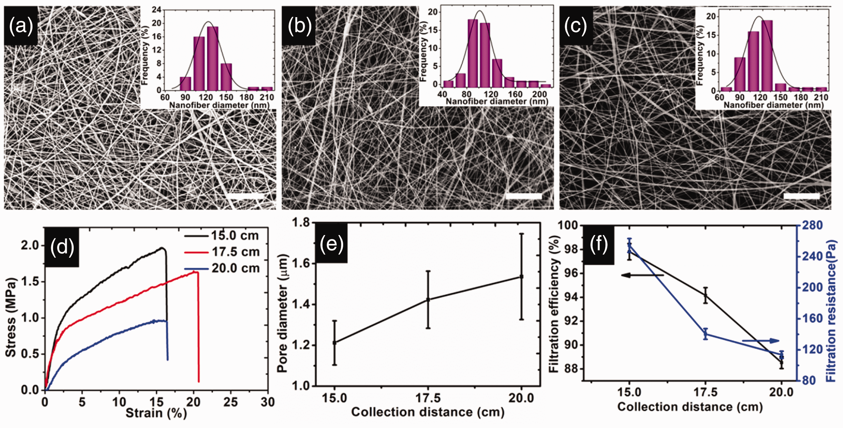
SEM images of different collection distances: (a) 15.0 cm, (b) 17.5 cm, (c) 20.0 cm; effect of different applied voltages on (d) stress–strain curve, (e) pore diameter, and (f) filtration property. Scale bar = 5 µm.
Effect of the spinning time on morphology, stress–strain, pore diameter, and filtration property of nanofiber membrane
The surface morphologies of nanofiber with different spinning times are shown in Figure 7(a) to (c). When the spinning times were 10.0, 12.5, and 15.0 min, the diameters of nanofiber were 108.64 ± 25.04, 119.15 ± 26.83, and 124.36 ± 22.23 nm, and the thicknesses of nanofiber membrane were 17.0 ± 4.4, 17.5 ± 5.1, and 18.6 ± 6.6 µm, respectively. We found that the diameters of nanofiber increased with the increase of spinning time. The reason was that the solution concentration increased with the increase of spinning during electrospinning. The influence of the spinning time on the stress–strain of nanofiber membrane is shown in Figure 7(d). When the spinning times were 10.0 and 12.5 min, respectively, their stress and stain were similar. Both stress and stain increased when the spinning time was 15 min, and this is because the density of nanofiber membrane increased on unit area. Impact of the spinning time on pore diameter of nanofiber membrane is shown in Figure 7(e). The pore diameter of nanofiber membrane had declined from 1.42 to 1.11 µm with the increase of the spinning time from 10 to 15 min. Figure 7(f) shows the effect of spinning time on filtration efficiency and filtration resistance. The filtration efficiency and the filtration resistance increased from 94% to above 99% and from 140 Pa to above 280 Pa with the increase of spinning time between 10 min and 15 min. The pore diameter of nanofiber membrane decreased alongside the increase of spinning time. It was easy to understand this trend. More time in spinning produced more nanofiber, which increased the thickness of the nanofiber membrane. When particles passed through nanofiber membrane, more nanofiber stopped particles because of thicker nanofiber membrane, which led to high filtration efficiency and filtration resistance. It was very important to choose a suitable spinning time in order to find a balance point between filtration efficiency and filtration resistance. The main reason was to ensure high filtration efficiency and low filtration resistance.

SEM images of different spinning times: (a) 10.0 min, (b) 12.5 min, (c) 15.0 min; effect of different applied voltages on (d) stress–strain curve, (e) pore diameter, and (f) filtration property. Scale bar = 5 µm.
Conclusions
In summary, a novel needleless electrospinning apparatus was used to prepare high throughput nanofiber membrane. The needleless electrospinning apparatus included a novel metal dish spinneret, solution automatic supply system, rotary roller collection system, temperature and humidity control system, high-voltage power supply system as well as transverse control system. High-quality and high-throughput nanofiber membrane could be produced for industrialization. Multiple jets had been observed by using a digital camera. The results showed that the number of jets could increase from 4 ± 1 to 32 ± 3 with the increase of applied voltage from 50 to 75 kV. Effects of the main spinning process parameter on surface morphology, stress–strain, pore diameter, and filtration property have been investigated systemically. The results showed that there was the same tendency between filtration efficiency and filtration resistance. It could be explained that large pore diameter of nanofiber membrane led to low filtration efficiency and low filtration resistance, which was not good for improving the filtration property of nanofiber membrane. On the other hand, small pore diameter of nanofiber membrane resulted in high filtration efficiency as well as high filtration resistance. We should find a balance point between filtration efficiency and filtration resistance to enhance the filtration property of nanofiber membrane. In this study, when solution concentration was 10 wt%, the applied voltage was 65 kV, correspondingly, and collection distance was 17.5 cm and the spinning time was 10 min. High-quality nanofiber membrane could be produced by using this novel needleless electrospinning apparatus. The high filtration efficiency and low filtration resistance were 94% and 140 Pa, respectively.
Footnotes
Declaration of conflicting interests
The author(s) declared no potential conflicts of interest with respect to the research, authorship, and/or publication of this article.
Funding
The author(s) disclosed receipt of the following financial support for the research, authorship, and/or publication of this article: This work was partly supported by the Chang Jiang Youth Scholars Program of China and grants (51773037 and 51373033) from the National Natural Science Foundation of China. This work has also been supported by grant (21802106) from the National Natural Science Youth Foundation of China. This work was also supported by Doctoral Program of Xi'an Polytechnic University (BS201902) Science and Technology Guiding Project of China Textile Industry Federation (2019005).