
Abstract
As the use of buoyant swimwear by children in residential swimming becomes more common, the investigation of the effects of buoyant textiles is crucial for the optimisation of functional buoyant clothing design. This study investigated buoyant knitted fabrics developed using an inlaid knitting technique for buoyant swimwear application. The impact of the inner diameter, outer diameter, and the linear density of the inlaid tube on the buoyant ability of the buoyant fabrics was analyzed using multiple linear regression. The result demonstrated that the fabric’s net buoyant force was significantly affected by all three parameters, with inner diameter having the greatest effect, followed by the outer diameter and linear density of the inlaid tube. The increase in the net buoyant force of the fabric can be predicted by the increase in the inner diameter of its inlaid tube and linear density and decrease in the outer diameter. The divergence of the results for specimens inlaid with Silicon tube and from the result predicted by multiple linear regression indicates that the net buoyant force is also affected by the linear density and the wall thickness of the inlaid tube. The new knowledge of this study can contribute to the production of buoyant layers inside the buoyant swimwear in replace of air chambers to improve the limitation of non-distributed buoyancy, accidental punctuation and bulkiness in conventional buoyant swimwear.
Introduction
The use of buoyant swimwear by children in residential swimming becomes more common, and various types of buoyant aids with inflatable devices are available in the market to assist young children to learn to swim [1]. An air chamber is a common feature in the design of buoyant swimsuits as air has low density and excellent buoyant ability. The density of air is 1.1415 kg/m³, whereas the density of freshwater and saltwater is 1000 kg/m³ and 1030 kg/m³, respectively [2]. Because the density of air is considerably lower than that of water, air is an excellent buoyancy agent used to improve the buoyancy performance of materials and advance the design of buoyant devices. In the past few decades, buoyant swimsuits with an automatic inflator for the air chamber have been fabricated [3–5]. Hernandez [1] suggested a design with a compressed gas cylinder, in which four inflatable bladders are attached to the front and the back of the swimming trunk. Orsos [6] was concerned about the appearance of buoyant swimwear and hence designed the tubular inflatable bladder to be stored inside the swimwear when not in use. Once the swimmer, with the aid of the swimsuit at a particular buoyancy, is sufficiently adept at the appropriate swimming technique, the buoyancy of the swimsuit can be adjusted by releasing the air inside the chamber [7].
However, the air chambers inside the inflatable buoyant swimsuit are vulnerable to puncture which leading to the potential risk of drowning for swimmers, particularly beginners [8]. Also, the bulkiness of inflatable buoyant devices makes the swimsuit cumbersome and uncomfortable [5]. In light of the expanding activewear market, the current design of the buoyant swimsuit, therefore, fails to meet the safety and aesthetic needs of the customer and industry. To improve the air chamber inside the buoyant swimsuit, Mitchell [9] developed a buoyant fabric by creating two layers of fabrics that sandwiched several containers of enclosed gas. The enclosed gas provides buoyancy and causes the clothing to float in water. Another buoyant fabric was created by laid-in knitting, in which 1–4 mm of buoyant material in the form of tube and foam rods was laid in to knitted fabric using the Half Milano stitch [10]. Furthermore, buoyant fibres such as polypropylene, polyethylene, kapok and milkweed fibres can be used in buoyant textile products due to their low density and the amount of air trapped between the fibres [11]. Han and Bai [12] developed a buoyant polypropylene fabric (PPF) to obtain photocatalysts for the degradation of organic contaminants in water. Another buoyant superhydrophobic fabric was developed for oil–water separation to solve the problem of oil pollution [13].
A review of previous studies indicates that buoyant fabric is commonly made of polypropylene fibres, which can float in water alone but are not buoyant enough to float the human body when used in buoyant swimwear. Additional buoyant tubes must be incorporated with polypropylene fabric to form buoyant fabric with the air inside the tubes as the main buoyant medium. By incorporating the advantages of knitted fabric, knitted buoyant fabric can improve the comfort of buoyant swimwear with hard foam and provide even distribution of buoyancy in the swimwear. Moreover, small air tubes are used as substitutes for the air chambers that usually appear on the conventional design of buoyant swimsuits to optimize the buoyancy of the fabric and provide sufficient buoyancy to float the human body. The inability to fabricate coarse buoyant tubes using a knitting machine can be overcome using inlaid knitting, which enables the inlaid materials that cannot be knitted as part of the loops of the ground structure to be securely incorporated into the fabric [14].
Inlay knitting technology
When a yarn carrier that supplies knitting yarn at the normal timing is used with a carrier that supplies knitting yarn prior to the normal timing, the yarn is obstructed from being hooked on to the knitting needles, and inlay knitting can be performed [15]. With advances in knitting technologies, laid-in knitted fabric structures have been used in the structural design as well as in industrial applications and pressure control of compression textiles for therapeutic purposes [16–18]. The inlay knitting technique is commonly used for reinforcing the knitted fabric. To form multi-layer knit fabrics with improved mechanical properties and promising lightweight applications, Abounaim et al. [16] applied the inlaid knitting technique to high-performance thermoplastic yarns. Balea et al. [17] studied that the course-wise direction with inlaid yarn is significantly reinforced and about five times less deformable with inlay yarns, primarily due to the behaviour of the inlays but not the knit. The inlaid knitted fabric can, therefore, have industrial applications for the development of net-shape fabrics. Moreover, it can be used to fabricate compression garments for medical use. Liu et al. [18] developed compression stockings using a weft inlaid knitted circular fabric; these stockings have been established as a cornerstone mechanical strategy in the prophylaxis and therapeutic management of varicose veins, venous thrombosis, and lymphoedema.
Buoyancy is the crucial factor for a buoyant swimsuit. When the swimsuit is composed of buoyant knitted fabrics, the choice of the suitable, lowest-density buoyant inlaid material is a key factor in the design of buoyant knitted fabrics. To improve the design of buoyant swimwear, it is important to investigate the effect of inlaid tubes on the buoyant performance of knitted materials. The buoyant force is affected by the weight and volume of the fabrics, which are determined by the number of inlaid courses and the physical properties of the inlaid tube when the fabrics are knitted applying the same parameters and same yarns. Apart from the number of inlays in the knitted fabrics, it is unclear how the design of the inlay tube (such as its inner diameter, outer diameter, and linear density) affects the buoyancy performance of the knitted materials. Thus, a total of nine inlaid knitted prototypes with three types of inlaid tubes of different diameters were fabricated. This study investigated the effects of the linear density, inner diameter, and outer diameter of inlaid tubes in the inlaid knitted fabrics on the net buoyant force of the inlaid knitted fabrics. The new knowledge in this study contributes to the development of a buoyant knitted fabric that can be used instead of conventional air chambers in buoyant swimwear.
Experimental design
To study the factors that affect the fabric’s buoyancy performance, the buoyant fabric was knitted with inlay knitting technology. The net buoyant force of the fabric was calculated using the density of the buoyant fabrics according to Archimedes’ principle. To evaluate the main factor that affects the net buoyant force of the fabric, the data obtained from the experiment were analysed using SPSS 23 (IBM Corp., Armonk, New York). Subsequently, the process of inferring buoyancy performance from the inner diameter, outer diameter, linear density, and wall thickness of the inlaid tube is detailed in the ‘Discussion’ section in three phases.
Preparation of material samples
Half Milano stitches are used to lay in the buoyant tube between the knitting loops. This stitch consists of one row of double jersey and one row of single jersey [19,20]. Its unique construction creates space between the loops situated in the front and back needle beds, enabling the filament to be laid in when knitting. Low density and air trapped between fibres are the key buoyancy characteristics of polypropylene (PP) [11,21]. PP yarn is therefore selected as the knitting yarn to fabricate the buoyant knitted fabric. Three tube materials with different diameters are sourced, including one made of polyethylene (PE), which is already used in life jackets for its buoyancy potential in textile materials [11]. As the inlaid tubes must be light in weight, floatable, flexible and soft enough for laying in during the knitting process, PE, polyvinyl chloride (PVC) and silicone are chosen. As PE varies widely in density, hardness, thickness and other physical and mechanical properties, it has diverse applications, from plastic bags and bottles to gas pipes with biodegradable properties [21]. PVC is a thermoplastic material that becomes soft and flexible when heated and retains a fixed configuration when cooled, depending on the amount and type(s) of plasticisers used [22]. It has been used for flexible medical tubing for more than 30 years due to its unique balance of cost saving and functional advantages [23]. Due to silicone’s high chemical inertness and good mechanical properties, it is widely used in tissue engineering [24]. It offers strong resistance to degradation by chlorinated water in swimming pools. The details and cross-section of each inlaid tube and knitting yarn are provided in Table 1.
The material used for inlay part and knitting part.

Fabric samples were knitted on a V-bed hand-knitting machine (Wealmart, Hong Kong, China). The machine gauge of the knitting machine (the number of needles per inch on the V-bed hand-knitting machine) was 7. The weight determining the take-down tension during knitting was pre-set at 364.55 g. Nine buoyant fabric samples of different inlaid materials were fabricated, and a basic knitted sample without inlays was taken as the control piece. The inlaid knitted fabric was knitted using three ends of the knitting yarn 75/72d Polypropylene and one end of the inlaid tube. All samples were prepared under the same knitting tension and knitting parameters, with a dimension of 38 courses that included 25 courses of inlays in a Half Milano stitch and 40 wales. The length of the inlaid tube was controlled to 337.56 cm with 2% variation. Figure 1 describes the knitting notation; the symbols  and
and  represent the double knit and single knit stitch, respectively. Finally, both ends of the inlaid tube are blocked by heat fusion. The pattern design and structural details of the inlaid fabric are presented in Figures 1 and 2. Five replicates were taken for each knitted condition. In the code denoting the components of the fabric, ‘PV’ means that the inlaid tube is made of PVC, ‘SI’ means silicone and ‘PE’ means polyethylene. The control fabric without inlays is given as ‘C’. The sample specifications are summarised in Table 2.
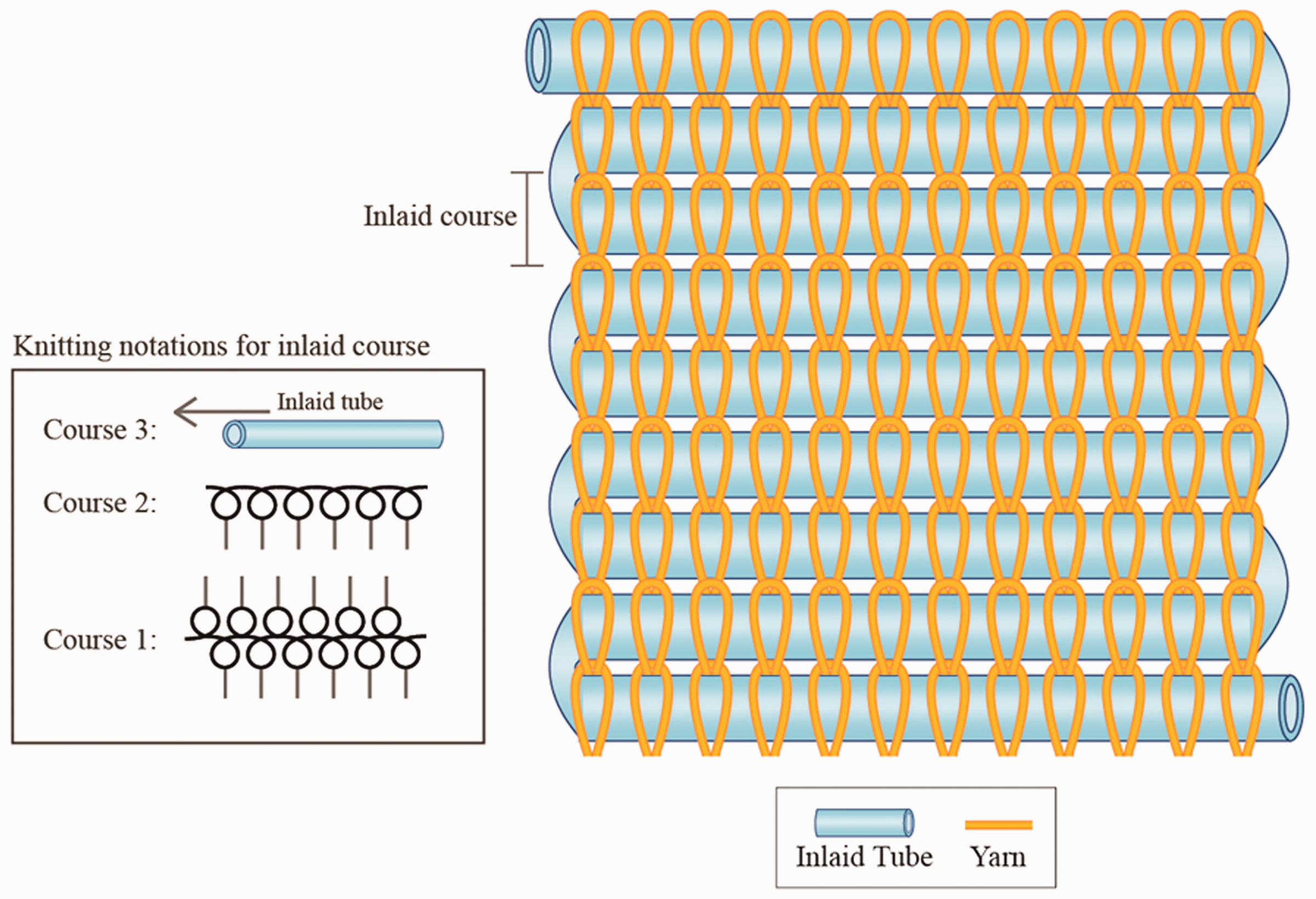
Pattern design of the inlaid knitted fabric.
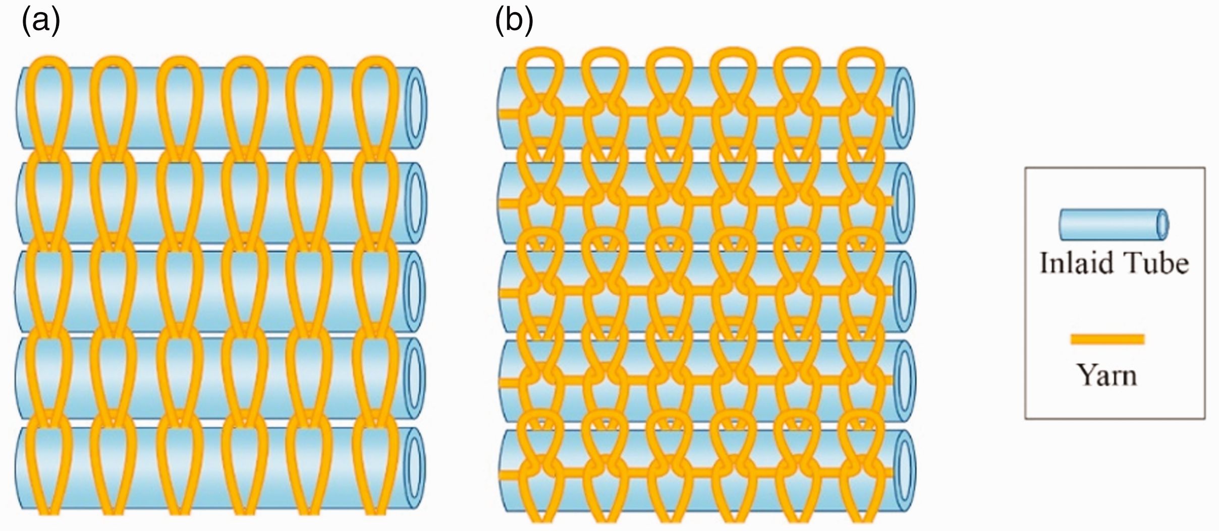
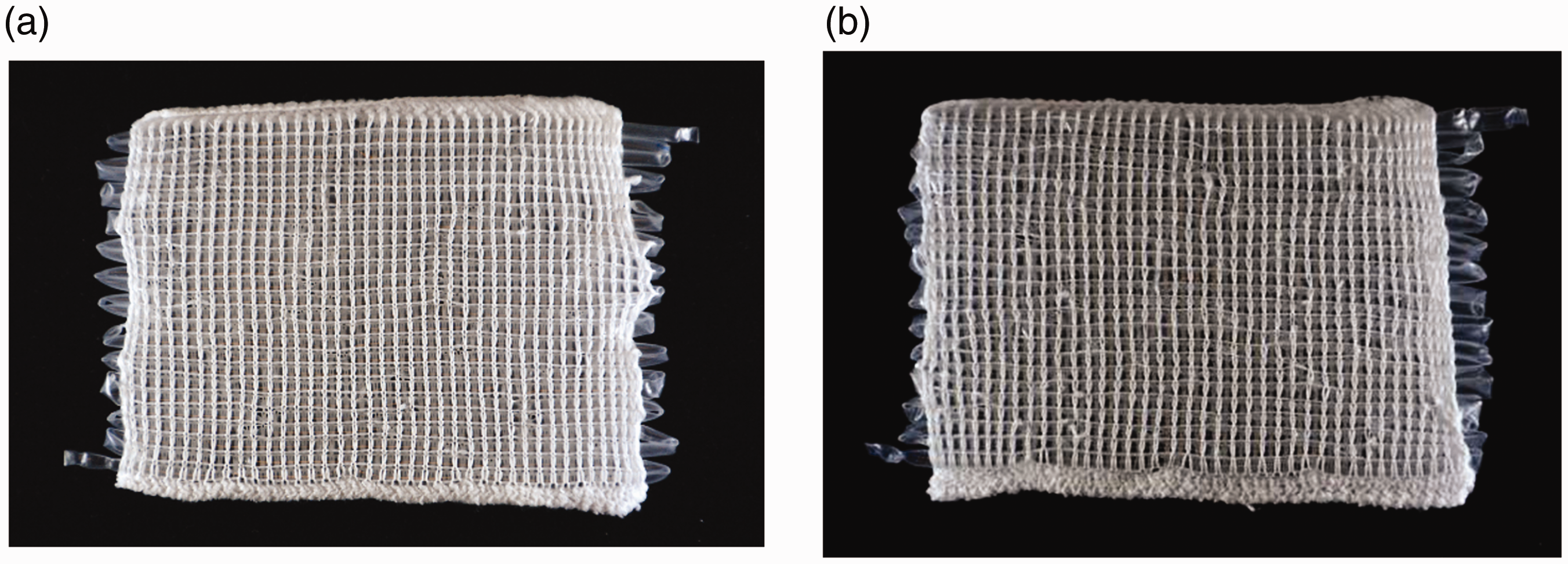
Image of inlaid fabrics with Half Milano stitch (a) front view of the knitting pattern of fabrics illustrating the arrangement of yarns (b) back view of the knitting pattern of fabrics.
Specification of inlaid knitted specimens with different inlaid materials and control fabric.

Measurement
To study the relationships between the buoyant force of the inlaid fabrics and linear density, inner diameter, and outer diameter of inlaid plastic tubes, the volume of the fabric sample was measured based on Archimedes’ principle. The fabric sample was placed in a water-filled vessel, where its volume was calculated based on the volume of water displaced. As the buoyant tubes of this study are highly compressible, a noncontact approach was adopted. The cross-section of the buoyant tubes was initially imaged with the Leica M165C stereo microscope, and the inner and outer diameters of the buoyant tubes were subsequently measured in four directions (Figure 3). According to Archimedes’ principle, a substance submerged in a liquid displaces a volume of liquid equal to its volume [25]. Thus, the volume of the fabric specimen was calculated by estimating the difference between the initial weight and the weight of the remaining water after the fabric had been inserted. Five specimens were knitted for each fabric type, and each specimen was tested three times. The mean value obtained from 15 tests was used and the images of inlaid knitted fabric PE3 and PE4 were shown in Figure 4.

Microscopic view of S2 tube (a) measuring outer diameter; (b) measuring inner diameter.
Front view of inlaid knitted fabric (a) PE3; (b) PE4.
Fabric density
Before calculating the buoyant force of the inlaid fabric, the weight and volume of the wet fabric were measured. For testing their density, pieces of inlaid fabric were immersed in water for 24 h in accordance with the International Organization for Standardization standard 12402-9:2006+A1:2011 (E) [26]. Subsequently, the fabric was taken out and laid flat on a metal rack (in the absence of a ventilating fan) until the interval between every two drops of water was greater than 30 s. It is assumed that the space in the knitted fabric was completely filled by water after being immersed in water for 24 h, and that the excess water in the specimens was removed by laying them flat on the rack. The weight of the wet fabric was measured using an electric balance that was equipped with a glass draft-shield and sliding doors. The mean value of the weight of each fabric obtained from 15 measurements was recorded (as Wf, in grams).
The fabric was placed in a vessel that was filled to the brim with fresh water. Subsequently, pushed by the lid, the fabric was submerged into the water, and the water was allowed to drain from the vessel. Until the draining of water stopped, a dry cloth was used to carefully dry the outer wall of the vessel. The weight of the vessel that was completely filled with water was measured and recorded (as W1, in grams). The wet fabric was submerged in the vessel by the glass lid until there were no air bubbles inside the bottle. When the water stopped draining, the weight of the whole system was measured using the electric balance and recorded (as W2, in grams). The test was repeated three times for each fabric sample.
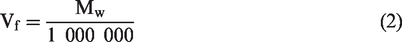
The mass of water displaced by the fabric in the vessel is
The fabric’s net buoyant force
Following Archimedes’ principle, the net buoyant force of the fabric is as follows [27]
Statistical analysis
The data from the experiment were analysed using SPSS 23 (IBM Corp., Armonk, New York). Multiple linear regression analysis was used to examine the relationships between the dependent variable (the net buoyant force of inlaid knitted fabric) and the following three independent variables: the (1) inner diameter of the inlaid tube, (2) outer diameter of the inlaid tube and (3) linear density of the inlaid tube. The significance level of the statistical analysis was set at 0.05. Histograms, Q–Q plots, as well as the measures of skewness and kurtosis indicate that the distributions of the net buoyant force, inner diameter, and outer diameter were significantly left-skewed. Therefore, a square root transformation was conducted on the inner diameter and outer diameter; the inverse transformation was conducted on the net buoyant force due to the positive skewness. Evaluation of the newly transformed distributions indicates that they were close to a normal curve.
Results and discussion
Previous research has shown that various foam rods and tubes can be fabricated to form a buoyant knitted fabric by inlaid knitting using the Half Milano stitch [10]. The lengthwise and widthwise elongation properties of the fabric are significantly influenced by the type of laying-in stitch used [18]. The gap in previous studies concerning the relationship between the design of inlaid materials and the buoyancy of the resulting fabric is filled in the current study. The key finding reported in this study is that the inner diameter, outer diameter and linear density of the inlaid tube and their interaction significantly affect the buoyancy performance of the inlaid knitted fabric. A higher net buoyant force means that the fabric is more buoyant. Figure 5 shows the schematic of the forces exerted on a buoyant knitted fabric. The experimental results and the result of multiple regression are listed in Tables 3 and 4 and plotted in Figures 6. The histogram and scatter plot of the actual and predicted buoyant forces are plotted in Figure 7.
Physical properties and net buoyant force of the fabrics.

Results of multiple regression analysis – Predictors of the net buoyant force.

Note: All coefficients are rounded to the nearest two decimals.
aSquare root of inner diameter.
bSquare root of outer diameter.
cInverse of net buoyant force.

Schematic of the forces experienced by a buoyant knitted fabric.
Net buoyant force
The result of the stepwise multiple regression analysis revealed that the three factors were significant predictors of the net buoyant force (F = 95.05, P < 0.001). With a β value of −2.39 (P < 0.001), the inner diameter of the inlaid tube was the strongest predictor of the net buoyant force of the fabric, accounting for 60.1% of the variance in the net buoyant force (Table 4). The second strongest factor was the outer diameter of the inlaid tube (β = 1.73, P < 0.001), accounting for an additional 7.1% of the variance in the buoyant force. The third strongest factor was the linear density of the inlaid tube (β = −0.22, P < 0.03). However, the linear density accounted for only 1.2% of the variance in the net buoyant force. These results indicate that a higher net buoyant force is a function of a larger inner diameter, smaller outer diameter, and larger linear density of the inlaid tube. Overall, the model explains almost 69% of the variance in the net buoyant force (R = .83). The regression equation for the fabric’s net buoyant force is as follows.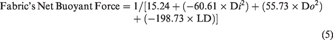
The result predicted by the regression equation is valid, as comparison of the predicted and actual net buoyant forces yields R2 = 0.85 (Figure 7(b)). PE4 had the highest net buoyant force, followed by PE3 (Table 3). The net buoyant force of PE4 was 13.7 times higher than that of the control fabric, which implies that the inlaid tube E4 significantly increased the fabric’s buoyant ability. PV1, PV2, SI2, and PE1 had a net buoyant force similar to that of the control fabric, indicating that these inlaid tubes had an insignificant effect on the fabric’s net buoyant force.
Phase 1 – The inner and outer diameters of the inlaid tube
The multiple linear regression analysis indicates that the inner diameter of the tube is the most important factor affecting the net buoyant force. As shown in Table 3, fabrics with a larger total gas volume tend to have a greater net buoyant force. Consistent with the analytical results, the inner diameter of S3 in SI3 is 19% and the total gas volume of fabric is 43% greater than that of P2 in PV2, but the net buoyant force of SI3 is 150% higher than that of PV2. The disproportional increase in the net buoyant force is attributable to the nature of the tube materials. Compared with P2, S3 is softer and more flexible, which may be due to the nature of the materials used, as silicone is more flexible than PVC. As the P2 tube is harder to bend on the fabric side when knitting, the tube is completely folded on both sides, which reduces the air stored inside the tube and thus decreases the total gas volume of the fabric and the net buoyant force. In Figure 6(a), the positive relationship between the fabric’s net buoyant force and its inner diameter is because the inner diameter of the inlaid tube determines the volume of the gas, which is the main buoyant medium. However, the net buoyant force decreased with an increase in the inner diameter and fabric’s gas volume from SI1 to SI2. Moreover, despite its higher net buoyant force, SI1 had an inner diameter (of S1) and gas volume of fabric smaller than that of PV1 and PV2 fabrics. To determine the reason underlying this aberrant result, the linear density of the inlaid tube was investigated, and the results are discussed in the next section.

Comparison of net buoyant force of inlaid fabrics with (a) inner diameter; (b) outer diameter of inlaid tube.
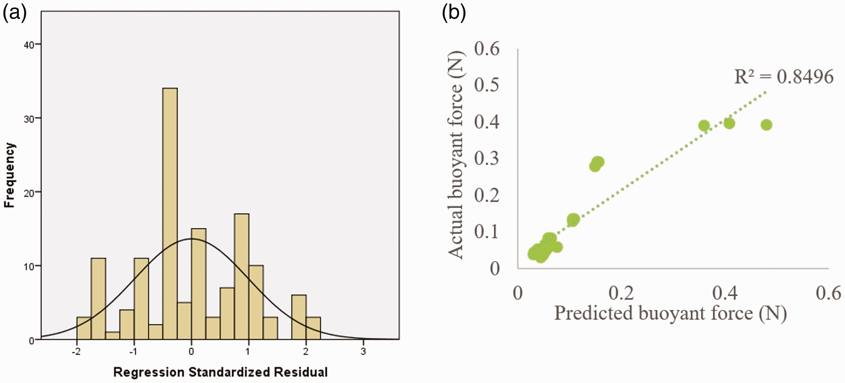
(a) Histograms of the distribution of inverse net buoyant force; (b) scatter plot of actual and predicted buoyant force.
The inner diameter of the inlaid tube affects the gas volume inside the tube, whereas the outer diameter controls the wall thickness of the tube. Therefore, the regression model predicted that the net buoyant force increases with an increase and decrease in the inner and outer diameters, respectively. Experimentally, the net buoyant force of the inlaid fabric increased with an increase in the outer diameter of the inlaid tubes (Figure 6(b)); the net buoyant force was the highest in PE4, followed by PE3. This result diverges from the predicted result of the regression model, possibly because the buoyant force is also affected by the linear density of the inlaid tube.
Phase 2 – The linear density of the inlaid tube
In general, the net buoyant force increased with an increase in linear density, which was consistent with the predicted result of the regression model (Table 3). The linear density of E2 in PE2 was similar to that of E3 in PE3, and it caused a steep increase in the net buoyant force. This is because the inner diameter of E3 was 57% larger than that of E2 (Table 3), meaning that the increase in the gas volume of the tube was disproportionately larger than the change in linear density. Therefore, the net buoyant force of PE3 was 107% larger than that of PE2.
In SI2, the linear density of S2 was triple that of S1 in SI1, but the inner diameter of S2 was only 50% larger than that of S1 and total gas volume of SI2 is 138% higher than that of SI1. Therefore, the increase in the gas volume was much lower than the change in linear density. Moreover, the linear density is affected by the wall thickness and the type of plastic material used in the tube. As both SI1 and SI2 were made of the same silicon plastic material and thus had the same plastic density, the lower net buoyant force might be due to the wall thickness of the inlaid tube (as discussed in phase 3). In addition, SI1 had a higher net buoyant force and a smaller linear density (of S1) than the PV1 and PV2 fabrics, consistent with the theoretical principle that a less dense object has greater buoyant ability [28]. Therefore, fabric SI1 had a higher net buoyant force than PV1 and PV2. However, this result diverged from the result predicted by the multiple linear regression. To investigate the reason why SI2, PV1 and PV2 have lower net buoyant force than that of SI1, the effect of the wall thickness of the inlaid tube on the fabric’s buoyant force was also investigated in the next phase.
Phase 3 – The wall thickness of the inlaid tube
The regression model indicates that the fabric’s net buoyant force is mostly affected by both the inner and outer diameters; these affect the wall thickness of the inlaid tube. Consistent with the expectation that the wall thickness remains constant regardless of the diameter of the inlaid tube, the gas volume increases with increases in the outer diameter of the inlaid tube. However, the wall thickness varies even among the same type of inlaid tubes; the wall thickness is similar between PE tubes of different diameters but dissimilar between the PVC and silicon tubes (Table 3). The large decrease in the net buoyant force of SI2 is because S2 had the thickest wall thickness among the inlaid tubes. The outer diameter of S2 was 81% larger than S1, but the inner diameter of S2 was only 50% larger than S1. This makes the wall of S2 109% thicker than that of S1 (corresponding to an increase in linear density of 200%). Compared with the inner diameter, the greater increase in the outer diameter of the inlaid tube causes an increase in the wall thickness and the tube’s weight, respectively. Consequently, the net buoyant force of SI2 is lower than that of SI1. The wall thickness of S1 in SI1 is also smaller than those of the PV1 and PV2 fabrics, making its net buoyant force higher than those of the fabrics with PVC tubes.
Conclusion
This research developed buoyant, inlaid knitted fabrics for buoyant swimsuit applications. It was observed that the inner diameter, outer diameter, and linear density of the inlaid tube significantly affected the fabric’s net buoyant force. It can be concluded that the inner diameter of the inlaid tube is the strongest predictor of the net buoyant force of the fabric, followed by the outer diameter and the linear density of the inlaid tube. These results indicate that the higher net buoyant force is a function of a larger inner diameter, smaller outer diameter, and larger linear density of the inlaid tube. The divergence between the results for fabrics inlaid with silicon tube and the buoyant force predicted by multiple linear regression indicates that the net buoyant force is also affected by the wall thickness of the inlaid tube. The net buoyant force of the silicone tubes (SI1 and SI2) decreased with increases in the inner diameter and gas volume. The large decrease in the net buoyant force of SI2 can be attributed to the thickest wall thickness of the inlaid tube (S2). Moreover, the smaller wall thickness of S1 in SI1 provided evidence of higher net buoyant force with a smaller inner diameter and linear density than that with PVC tubes. By taking advantage of the flexible silicone, more gas can be stored at the corner of the tube at the fabric edges, which implies that silicone performs better than PVC. In future research, knitted fabrics made using different types of stitch should be investigated to establish the relationship between knitting stitches, buoyancy and the mechanical properties of buoyant knitted fabrics.
Footnotes
Declaration of conflicting interests
The author(s) declared no potential conflicts of interest with respect to the research, authorship, and/or publication of this article.
Funding
The author(s) disclosed receipt of the following financial support for the research, authorship, and/or publication of this article: The authors would like to thank the Departmental Grant of Institute of Textiles and Clothing, The Hong Kong Polytechnic University (grant number PolyU RPPU) for funding this project.