
Abstract
Based on the problem of shape-preserving property of complex geometry shape preform, a kind of new fabric with thermal bonding layers was designed in our work. From the apparent view, it can be seen that the carbon cloth was attached with a layer of thermal bonding layer structure. The two adjacent carbon fabrics can be bonded together by the thermal bonding layers through hot press actions. Because of the particular characteristics, this type of fabrics can help to achieve the overall integrity of complex geometry shape preform. This kind of particular fabric with thermal bonding layers was prepared by 3D weaving process using carbon fiber and thermoplastic nylon fiber. To evaluate the effect of thermal bonding layers on shape-preserving property of fabric, the fabrics were prepared with five different contents of thermoplastic nylon fiber. And the pure carbon cloth without thermoplastic nylon fiber was also prepared as control group. The shape-preserving property of fabric was evaluated by single-wing springback test and fabric peeling test in the 0° and 90° direction. The experimental results show that the effect on shape-preserving property of fabric enhanced with the increase of contents of thermoplastic nylon fiber, and the shape-preserving property of fabric was more significant in 0° direction compared with 90° direction.
Keywords
Introduction
Carbon fiber reinforcement polymer composite materials have increased exponentially among the most important material development in recent years due to their many advantages. Liquid composite molding process such as resin transfer molding (RTM) is widely used in the preparation of composites due to its low cost and other advantages. How to place dry carbon fiber preforms into the mold efficiently is an important step [1]. Ply stacking is a common way to spread the single-layer-reinforced fabric into the mold separately to achieve the required thickness and shape of the final preforms. In the process of preparing the preform, especially complex geometry shape structure, carbon fabrics usually need to be bended in the edge locations. In the bending process, the carbon fabrics will be deformed. Because there are a number of fabric layers, the layers will interact with each other and cause friction or sliding. It may cause the phenomenon of fabric wrinkling or uneven thickness and be harmful to both the final shape of complex geometry preform and the mechanical properties of final composites [2]. In order to reduce the adverse effects of the above problems and achieve better shape integrity of the final preform, it is a good idea to bond the adjacent fabric layer using binder. Relevant scholars have also carried out continuous research on tackified fabrics.
As early as the end of the 20th century, Rohatgi and Lee [1] explored the mechanism of the influence of the binder on the fabric preforming and analyzed it from many factors including the concentration and type of the binder. The researches of Shih and Lee [3] and Estrada et al. [4] showed that the concentration and location of tackifier in the preform affect the preform permeability. Sun et al. [2] studied the effects of different concentrations’ tackifier content on the shape-preserving property of tackified fabrics. Some scholars have studied the effect of binder on the mechanical properties such as interlaminar properties [5–7], compressive properties [8], and flexural properties [9] of composites. Some scholars have also done relevant researches on the addition form of binder and its influence. For example, Tanoğlu et al. [6] and Shih et al. [10] used powder binder and studied its effect on the mechanical properties of composites. In Beier et al.’s research [11], binder of non-woven mats was utilized to prepare novel preforms. Doris et al. [12] used the phenoxy introduced as a chopped fiber interleaf between the carbon fiber plies to prepare the composites. In addition, in the automatic lay-up technology [13], binders are also required to play an indispensable auxiliary role. Wang et al. [14] also demonstrated that a hot press tackified preform can improve the uniformity of the laminates thickness, and the tensile and compressive strengths of the tackified laminates are improved obviously in recent research. Zhao et al. [15] established a new model called “Gradual Deformation Model” as deformation assumption to describe the different bias extension behaviors of tackified woven fabrics.
In addition, many researchers also used the way of fiber hybridization by mixing high performance fibers and thermoplastic fibers to prepare preforms or composites. In general, there are three kinds of hybrid configurations available: there are termed interlayer, intralayer, and intrayarn hybridization [16]. In interlayer hybrids, each ply contains only one fiber type, but plies of different fiber types are stacked onto each other [17]. In intralayer hybrids, each ply contains both fiber types, for example by co-weaving [18]. In intrayarn hybrids, the fiber types are mingled within a yarn [19].
High performance fibers are bonded by thermoplastic fibers after hot pressing during the three processes, and the preparation of thermoplastic composites can be realized through post-curing process. In recent years, some scholars interleaved electrospun thermoplastic nanofibrous veils in carbon/epoxy composite laminates and researched the effects of the nonwoven veils on interlaminar toughness of carbon/epoxy laminated composites. The thermoplastic fiber raw materials used include polyester fiber [20], polyamides fiber [21–24], and so on. Results of the above studies all showed that the presence of interlaminar thermoplastic veils improved the interlaminar toughness of carbon/epoxy composites.
It can be summarized from the above-mentioned literature study that binders play a great role in the preparation of preforms. The binders and their related functions have been deeply studied by experts and scholars all the time. However, the author found that the binder is separated from the fabric layer regardless of the forms of powder, liquid, or network in the above work. That is, the binder is coated or covered on the fabric surface to bond the fabric layer and achieve the finalizing bonding effect. Interlayer hybrids also belong to this condition. Furthermore, intralayer hybrids and intrayarn hybrids belong to the condition that thermoplastic fibers and high performance fibers are intermingled with each other. So, in order to make the binder play a role more efficiently and conveniently in preparing preforms, our research team absorbs the inspiration of hybrid configurations to design a new type of fabric different from previous technological process, in which the thermal bonding fiber and carbon fiber are woven together through the structural design. Among them, thermoplastic fiber can be used to play the role of binder and helped to achieve the SPPF by hot press before liquid molding process such as RTM process. The advantage of this new fabric is that the content of thermal bonding fibers can be effectively controlled by weaving process design, and the thermal bonding fibers can be evenly distributed on the carbon base cloth. In addition, due to the regularity of weaving process, most of the thermal bonding layer can be overlaid on the carbon base cloth to achieve interlayer effect and some points are interwoven with carbon cloth regularly to achieve co-weaving effect. The purpose of this research is to mainly study how to design and prepare such new fabrics and the effect of content of thermal bonding fibers on SPPF.
Design and preparation of new fabrics
Among the available thermoplastic fibers, polyamide fibers are considered as a good candidate due to its properties such as low cost, good thermal stability, low dielectric constant, high mechanical strength, easy handling, and chemical inertness [25]. So, TPNF matched with carbon fiber is chosen as raw materials for the new fabric design and preparation. The TPNF is chosen as binder. In order to evaluate the effect of the content of TPNF on the SPPF, the new fabrics with five different contents of TPNF had been designed and prepared, and the pure carbon cloth without TPNF was prepared as the control group.
The new fabrics were woven by self-developed 3D weaving loom (from Institute of Textile Composites, Tiangong University), and the raw materials included T300-3K carbon fibers (from Toray, Japan) and TPNFs (from Hubei Yutao Special Fiber Co. Ltd, China). The most significant characteristics of TPNFs is its low melting point. The melting point of TPNFs was tested according to differential scanning calorimetry (DSC) measurements as shown in Figure 1. It can be seen that there are two melting points shown in red circles, which are about 87 and 101°C. It may show that TPNFs have the characteristics of low melting point by adding another component.

The differential scanning calorimetry curve of TPNFs.
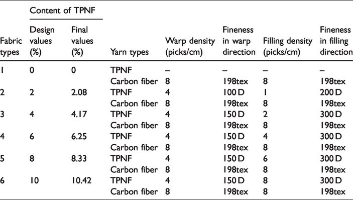
According to the design concept of the new fabrics, the finished fabrics look like that the TPNFs are “growing” on one side of the carbon fabrics as a thermal bonding layer. That is, one side of the fabrics looks like a simple carbon fiber structure layer, and the other side is a TPNF layer attached to the carbon fiber structure layer. The fabric structure of carbon fabrics was first determined as five-heddle satin and set the warp and filling density as 8 picks/cm. According to the structure design of carbon satin fabric, its areal density is 320 g/m2. In addition, the warp density of TPNF layer was set as 4 picks/cm. The five contents of TPNFs were designed according to the weight ratio of unit area, which were 2, 4, 6, 8, and 10%, respectively. Then the content and configuration of TPNF were calculated and corrected by taking design factors into consideration. These factors include the fineness of TPNF, fabric structure, and manufacturing process. Finally, five contents of TPNF were settled down according to the weight ratio of unit area, which were 2.08, 4.17, 6.25, 8.33, and 10.42%. In addition, the filling densities of thermal bonding layer were settled down too. The structural parameters of new fabrics are shown in Table 1. In addition, to provide the control group for the follow-up experiment, pure carbon cloth of five-heddle satin was prepared, and its parameters were also put in Table 1. Since there is no thermal bonding layer, the content of TPNF of pure carbon fiber cloth is recorded as 0%. The content of TPNF in the warp direction and filling direction is shown in Table 2.
Structural parameters’ table of new fabrics.
The content of TPNF in the new fabrics.

The schematic diagrams of fabric structure with six contents are shown in Figure 2. The figure shows the fabric structure under the yarn number within two organizational cycles. Figure 2(a) shows the apparent observation from one side of the fabric with different contents of TPNF, which is shown as carbon fiber structure layer. Figures 2(b) to (g) show the apparent observation from the other side of the fabric with different contents of TPNF, which is shown that the structure layer of TPNF is attached to the carbon fiber structure layer. Green refers to carbon fiber and yellow refers to TPNF in Figure 3. Figure 3(a) to (g) shows the pictures of real fabrics corresponding to Figure 2(a) to (g), respectively.

The schematic diagrams of new fabric structure: (a) the apparent observation from one side of the fabric with different contents of TPNF; (b)–(g) the apparent observation from the other side of the fabric with different contents of TPNF (0, 2.08, 4.17, 6.25, 8.33, and 10.42%).

The photographs of real new fabrics: (a) the apparent observation from one side of the fabric with different contents of TPNF; (b)–(g) the apparent observation from the other side of the fabric with different contents of TPNF (0, 2.08, 4.17, 6.25, 8.33, and 10.42%).
Experimental
In order to study the influence of TPNF’s contents on the SPPF, the test of shape-preserving of fabric and fabric peeling test was designed, respectively. The influence degree was characterized by the springback angle and the fabric peeling strength obtained from the tests.
The test of SPPF
Test device design
In order to make the test of shape-preserving of fabric simple and effective, a simple test device was designed, and its schematic diagram is shown in Figure 4. The test device mainly consists of three parts: part (a) is the device body, which is used to support the fabric body; part (b) is the upper cover of the device, which is used to assist the process of fabrics presetting. It can keep the part of fabric above the device from moving during the test of shape-preserving of fabric. Part (c) is the side cover of the device, which is also used to assist the fabric presetting. And it is removed in the beginning of the test of shape-preserving of fabric to release the inner fabric flank for the subsequent single-wing springback test. In order to ensure that all types of fabrics have the same thickness in the presetting process, it was rounded on the top right corner of main body and the inside of side cover to make the mould cavity fixed with 2 mm space. The 2 mm space is used for placing and tightening fabrics in the presetting process.
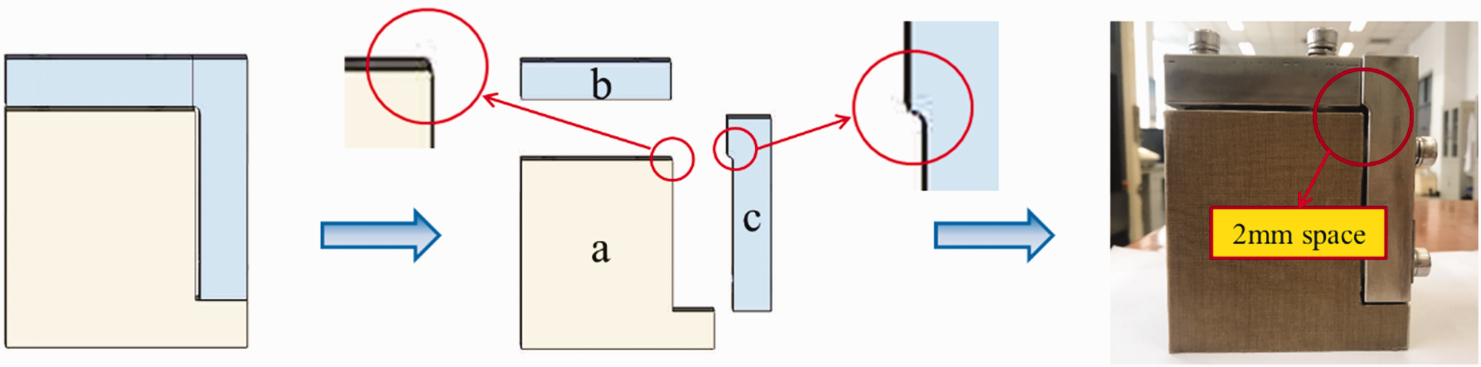
The schematic diagrams and real photograph of test device.
Preforming of new fabrics
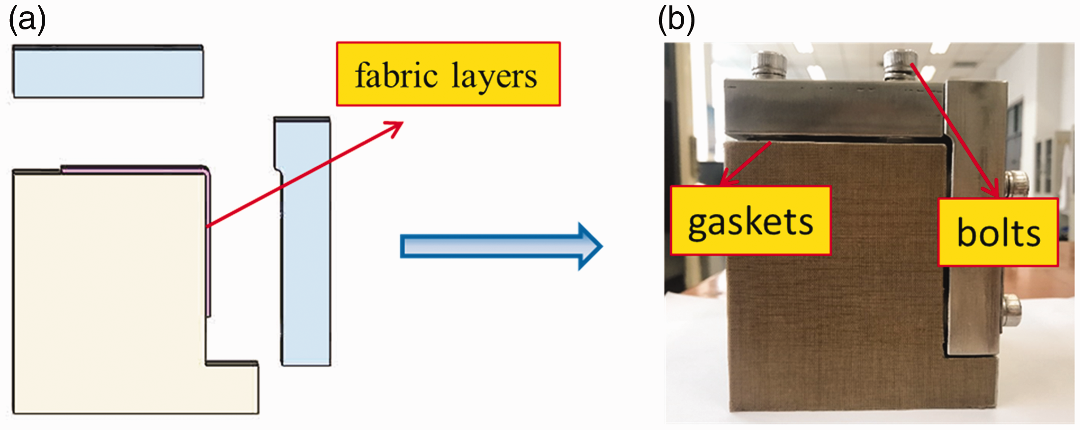
YG141L fabric thickness gauge was used to measure the thickness of all types of fabrics under the same pressure. The number of fabric layers was determined to be six and kept consistent. All types of fabrics were tailored according to the size of warp × weft as 120 mm × 60 mm. The layout diagram is shown in Figure 5. Since the new fabrics contain thermal bonding layer, the top layer of new fabrics needs to be replaced with a pure carbon fabric layer to avoid thermal bonding layer bonding on the device during the presetting process. The ply stacking diagram is shown in Figure 6. In order to describe conveniently, warp and weft directions are defined as 0° and 90° directions, respectively. Fabrics layers were put on the device body according to 0° and 90°, respectively, as shown in Figure 7(a). Then gaskets were put into the cavity of the device, and bolts were used to tighten the device to ensure that the final compacted fabric had a consistent thickness of 2 mm as shown in Figure 7(b). Finally, the fabric system composed with fabrics and device was put into an oven at 125°C. The temperature during the preforming process was chosen through previous test about melting effects of different fineness of TPNFs. The TPNFs with different fineness (100 D, 150 D, 200 D, and 300 D) were put in oven (from Sorenyi Technology Co. Ltd, China) to observe their melting effects. In order to balance the melting temperature of different fineness of TPNFs and the time of subsequent experimental process, it is necessary to choose an appropriate temperature. According to our observation, 125°C is an appropriate temperature. So, 125°C was chosen as the bonding temperature during the presetting process. JM426 portable digital thermometer was used to monitor the temperature of fabrics within the device. The temperature of fabrics needs to be 125°C and maintained for 30 min, which made the TPNF melt in the condition of hot press to bond fabric layers and achieve presetting of fabric preform. Besides, pure carbon fabrics without TPNF was operated in the same way as a control group.

Layout schematic diagram of tailoring fabrics.

Ply stacking schematic diagram of fabrics.
The schematic diagrams and real photograph of presetting process.
Single-wing springback test
The fabric system was removed from the oven and placed on the laboratory bench when cooled to room temperature through 12 h. Carbon fiber structure layers were bonding together with TPNF structure layers to form an integral preform during the cooling process. The position of the high-speed camera was adjusted to make the lens face the side cover of the device. The software PFV Ver.351 equipped with the high-speed camera was used and opened to observe the fabric system in the shooting window. Then the high-speed camera was further adjusted to leave an enough space for observing the single wing of preform in the shooting window. The single wing of preform refers to the part of the fabric that hangs down on the side of the test device. Finally, the side cover was removed, and the single wing of preform was released. At the same time, the camera shooting was run to record the change process of single-wing springback in the initial period. When the single wing of preform was completely unpressed, it was recorded as time 0, and the timing started from time 0. The high-speed camera was used to record the springback angle change of the single wing of preform at 0.25, 0.5, 1, 2, 4, 6, and 8 h, respectively. The test system is shown in Figure 8. And the springback angle is shown in Figure 9.

The real photograph of test system.

The schematic diagram of springback angle.
Fabric peeling test
In accordance with ASTM D1876, the T-shaped fabric peeling test was carried out on the preforms with thermal bonding layers after single-wing springback test. The effective size of the fabric peeling samples was 60 mm × 60 mm. It is necessary to prepare the fabric peeling samples before the test. A precast notch was made carefully across the width of the sample with a knife. The depth was required to be between the preforms. The specimens were cut in such a way that the length of unbonded ends was 30 mm. Finally, the two unbonded ends were pulled apart at a rate of 100 mm/min on an electronic universal testing machine with a 1 kN load cell at room temperature. The peeling length was not less than 50 mm. The schematic diagram and real photograph of T-shaped fabric peeling test are shown in Figure 10.

The schematic diagrams and real photograph of T-shaped fabric peeling method.
Results and discussion
Effect of thermal bonding layers on the SPPF
During the presetting process, the fabric was given a 90°C bend to form the single wing. The bending of fabrics caused the restoring force of the fabric itself. After removing the side cover of test device, the fabric has the tendency of restoring to its original state due to the restoring force. Because the new fabric contains TPNF, it will bond carbon fiber layers inside the preform after hot press. This can help to hinder the recovery trend to achieve the shape-preserving of fabric. With the increase of the content of TPNF, the number of bonding points between fibers in the preform increases. The increase of the bonding ability between layers will cause the decrease of the springback angle. And the smaller the springback angle, the better the SPPF is. When the restoring force is more than the bonding force, the preform will also generate springback. The effect of different contents of TPNF on the SPPF was evaluated by observing the change of springback angle. The springback angle θ between the single-wing fabrics and device body was measured using the angle measurement function of PFV Ver.351 software.
Initial stage of fabrics springback
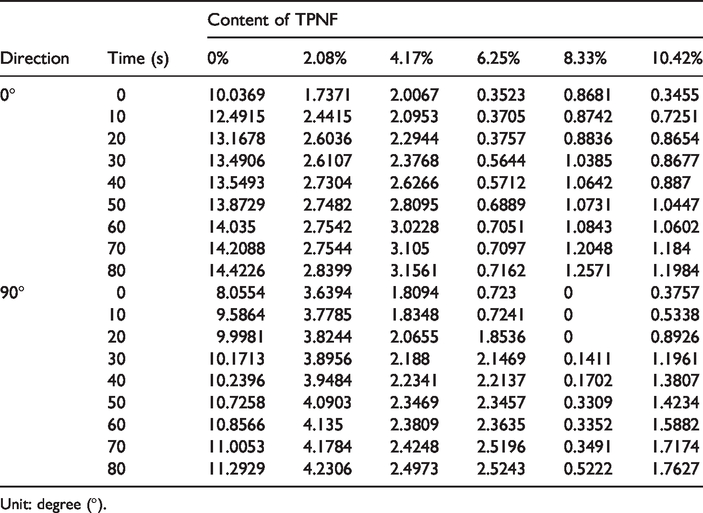
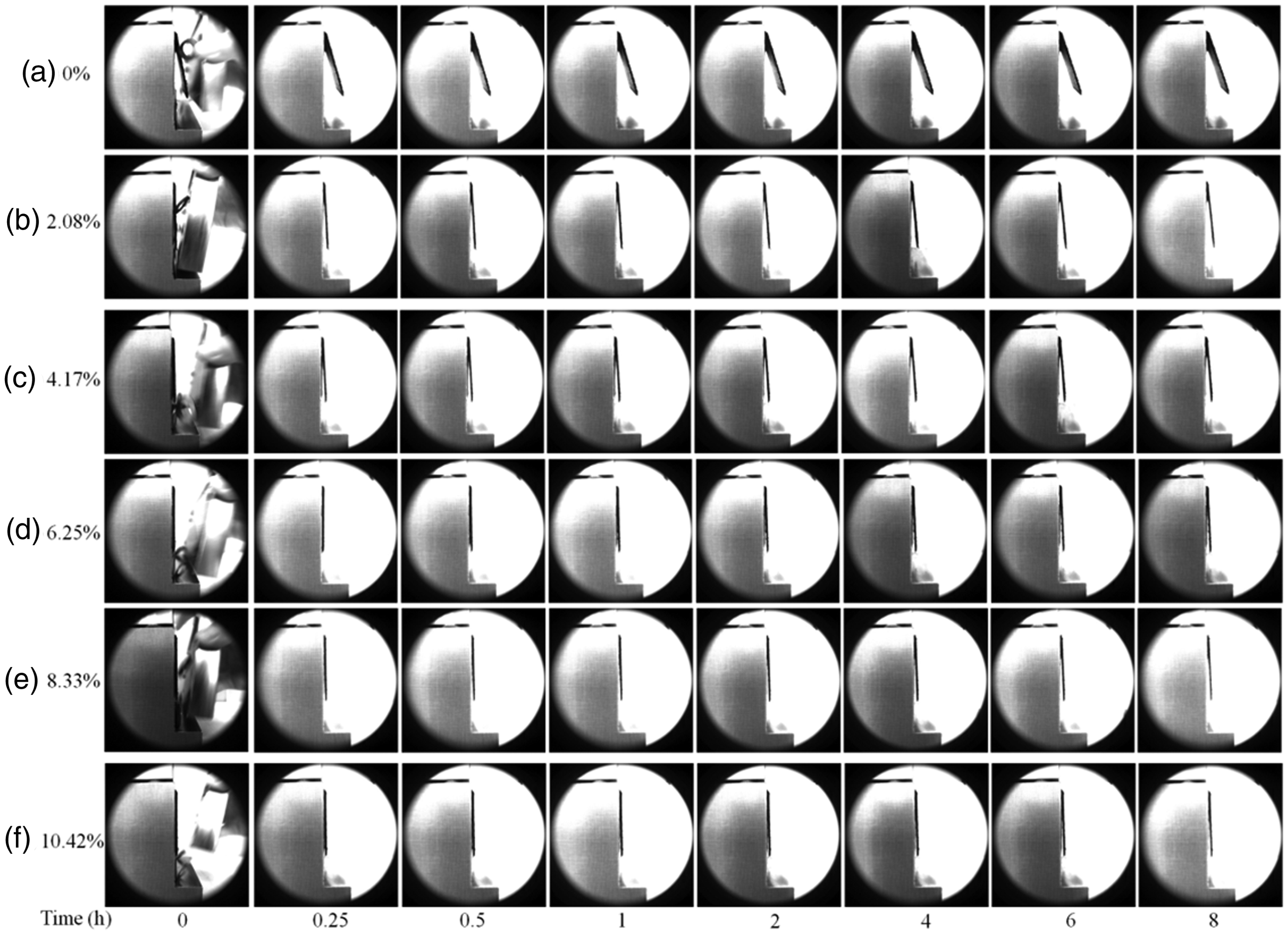
In the initial stage of completely releasing external force, the springback phenomenon of the single wing was obvious and recorded by high-speed camera. Taking 10 s as an observation period, the springback angle of single wing in the initial 80 s stage was recorded as shown in Table 3. In order to reflect the change trend of springback angle more intuitively, the polyline graph was drawn in Figure 10. Figures 11(a) and (b) are shown the springback angle of all kinds of fabrics in 0° and 90° directions, respectively. Figures 12 and 13 are the corresponding actual observation diagrams.
Springback angles of single-wing fabrics in the initial 80 s stage.
Unit: degree (°).

The polyline graph of springback angles of single-wing fabrics in the initial 80 s stage: (a) 0° and (b) 90° direction of the preforms.

The actual observation diagram of springback angles of single-wing fabrics in the initial 80 s stage in 0° direction.

The actual observation diagram of springback angles of single-wing fabrics in the initial 80 s stage in 90° direction.
As seen from Figures 12 and 13, in the initial stage of completely releasing external force, the springback angle of pure carbon fabric (0%) without thermal bonding layer is significantly higher than that of other groups with thermal bonding layer. It is shown that the existence of thermal bonding layer can effectively prevent the phenomenon of fabric springback and play a good role in shape-preserving of fabric. It can be seen that the springback angle also showed a decreasing trend with the content increase of TPNF in the 0° direction in Figure 11(a). The springback angle is the smallest, and the springback phenomenon is the weakest when the content is 6.25%, which indicates that the springback speed is the lowest in the initial stage, and the function of shape-preserving of fabric is the best. It can be because TPNF is more evenly dispersed in 0° direction when the content is 6.25%. The position containing TPNF will produce the better bonding force under hot press, and TPNF will not appear to interfere with each other after cooling. So, the fabric system of 6.25% can produce a better bonding effect in 0° direction. In addition, for 0° direction, the springback angle variation between nylon content 2.08 and 4.17% was very low. Similar low difference in springback angle was observed between nylon content 8.33 and 10.42%. That is to say that the change tendency of springback angle is consistent under the 0° direction within a certain content range, namely the SPPF tends to be consistent. It can be seen that the springback angle showed a decrease trend with the content increase of TPNF in the 90° direction too in Figure 11(b). The springback angle is the smallest, and the springback phenomenon is the weakest when the content is 8.33%, which indicates that the springback speed is the lowest in the initial stage and the function of shape-preserving of fabric is the best. It can be because TPNF is more evenly dispersed in 90° direction when the content is 8.33%. The position containing TPNF will produce the better bonding force under hot press, and there is a little gap of one filling yarn between the cycles of TPNF in filling direction. It can help to decrease the interference with each other after cooling. So, the fabric system of 8.33% can produce a better bonding effect in 90° direction. In addition, for 90° direction, the springback angle variation between nylon content 4.17 and 6.25% was very low. That change tendency of springback angle is consistent under the 90° direction within a certain content range, and the SPPF tends to be consistent. It shows that the change of the springback angle of 0° and 90° direction presents a similar rule to a certain extent.
Subsequent stage of fabrics springback
The single-wing springback angle of all types of fabrics was recorded in Table 4 after placed for 0.25, 0.5, 1, 2, 4, 6, and 8 h. In order to reflect its change trend more intuitively, the polyline graph of springback angles is drawn in Figure 14. Figure 14(a) and (b) reflects the trend of the springback angle of all kinds of fabrics in the 0° and 90° directions, respectively. And Figures 15 and 16 are the corresponding actual observation diagrams.
Springback angles of single-wing fabrics in subsequent stage.

Unit: degree (°).

The polyline graph of springback angles of single-wing fabrics in subsequent stage (a) 0° and (b) 90° direction of the preforms.
The actual observation diagram of springback angles of single-wing fabrics in subsequent stage in 0° direction.

The actual observation diagram of springback angles of single-wing fabrics in subsequent stage in 90° direction.
As seen from Figures 15 and 16, the single-wing springback angle of all types of fabrics increases slowly as time goes on. However, the overall increase trend shows a change process from fast to slow, and the higher the content is, the slower the increase trend of springback angle. Moreover, the springback angle of pure carbon fabric (0%) without thermal bonding layers was significantly higher than that of other groups with thermal bonding layers. It can also show that the existence of thermal bonding layers can play a good role in the shape-preserving of fabrics. As seen from Figure 14, the springback angle showed a decrease trend with the content increase of TPNF either in the 0° direction or in the 90° direction. From the contrast between Figure 14(a) and (b), it can be seen that the springback angle in 0° direction is lower than that in 90° direction at the same content of TPNF of all types of fabrics. This is because 0° direction is warp direction, namely the direction of weaving. The TPNF dispersed more uniformly between layers in the 0° direction than that in 90° direction. In 0° direction, per TPNF is shorter than 90° direction, and there is more gap between TPNFs than 90° direction, even for the fabrics with 10.42% bonding layer. So, the dispersion state of TPNF in 0° direction can provide more uniform bonding effects than 90° directions. That is, the SPPF is more significant.
Fabrics peeling strength
Peeling force–displacement curve
In the process of peeling, electronic universal testing machine can record the peeling force and displacement automatically. Figure 17(a) and (b) is peeling force–displacement curve of various fabrics with TPNF in the 0° and 90° directions, respectively. As seen from Figure 17, with the increase of TPNF contents, the peeling force presents an overall upward trend with the increase of displacement.

The peeling force–displacement curve of fabrics: (a) 0° and (b) 90° direction.
Figure 17 also shows that the state of fabric peeling is different with different contents of TPNF. When the content is 2.08%, it can be seen from Figure 17(a) that the wave peak presents obvious periodic changes when the peeling force was along the 0° direction. This is because the filling insertion configuration of TPNF is one root inserted with seven picks empty. For describing easily, this filling insertion pattern of TPNF is recorded as pattern “1 VS 7.” The filling insertion pattern is based on the minimum cycle number of TPNF and carbon fiber introduced in weft direction. The first number represents the number of TPNF introduced in weft direction within the minimum cycle number, and the second number represents the interval fiber number of between two picks of TPNF in weft direction within the minimum cycle number. So, the filling insertion patterns of TPNF under the content of 2.08% are recorded as “1 VS 7,” and the minimum cycle number in weft direction is 8 picks/cm. Correspondingly, the filling insertion patterns of TPNF under the content of 4.17, 6.25, and 8.33% are recorded as “1 VS 3,” “1 VS 1,” and “3 VS 1,” respectively, and the minimum cycle numbers in weft direction are 4, 2, and 4 picks/cm, respectively. In the content of 10.42%, the filling insertion pattern of TPNF is same as the way of carbon fiber. It can also be recorded as “1 VS 0” using this kind of filling insertion pattern, and the minimum cycle number in weft direction is 1 picks/cm. The structural configuration can be clearly seen from Table 5. The purple refers to TPNF filling insertion in weft direction. The bonding function is enhanced where the TPNF exists. When the fabric was peeled along the 0° direction, the peeling force obviously increased at the position where the TPNF existed, and a wave peak appears as shown in Figure 17(a). When the fabric was peeled along the 90° direction, the peeling force tended to be more uniform due to the bonding function caused by the position where the TPNF existed, which is shown in Figure 17(b).
The code of nylon fiber filling insertion patterns.

But this change rule of peeling force will become less obvious with the increase of contents of TPNF. The reason is that the number of interval weft fiber number of TPNF is different with the difference of TPNF contents in the structural parameter design. The more the number of interval weft fiber between two adjacent TPNF, the more obvious this phenomenon will be. However, the less interval weft fiber number of TPNF, the more the bonding function of TPNF will be, which can help the near part without TPNF to bear the peeling force. This function can be called as a “compensation mechanism,” and this will weaken the obvious wave phenomenon. So, it can be seen that the change rule of peeling force is similar in the 0° and 90° directions at the contents of 4.17 and 6.25%. When the content of TPNF increases to 8.33% or above, it is obvious that the peeling force shows a great increase. This is because the “compensation mechanism” caused by pattern “3 VS 1” of 8.33% is more effective than that by pattern “1 VS 1” of 6.25%, and the bonding function is greatly improved. Correspondingly, the peeling force continues to increase at the contents of 10.42%.
Fabrics peeling strength
The peeling process with the peeling displacement between 20 and 50 mm was selected and analyzed. In this process of peeling, the maximum and minimum peeling force are recorded, and the average peeling force is calculated. The maximum, minimum, and average peeling strength are calculated according to the following formula
Fabrics peeling strength of all types of fabrics with different contents of TPNF.

Unit: kN/m.

Bar charts of fabrics peeling strength.
Internal morphology of preform
The internal morphology of preforms was observed by optical microscope at 6.5 times magnification after fabric peeling test. Figures 19 and 20 are the microscopic photographs of the internal morphology of various preforms with TPNF after fabric peeling test in the 0° and 90° directions. As seen from the microscopic photographs, the carbon fiber extraction phenomenon becomes more obvious with the increase of the content of TPNF in the peeling process, and the length and quantity of the extracted carbon fibers increase. This is due to the number of bonding points between fibers in the preforms increases with the increase of the content of TPNF. Therefore, the bonding ability between layers increases, which cause the increase of peeling strength.
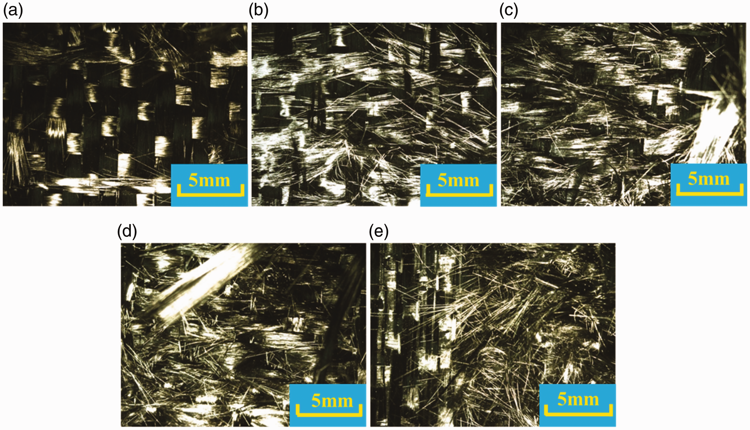
Internal morphology of the preforms after fabric peeling test in 0° direction at 6.5× using microscope: (a) 2.08; (b) 4.17; (c) 6.25; (d) 8.33; (e) 10.42%.

Internal morphology of the preforms after fabric peeling test in 90° direction at 6.5× using microscope: (a) 2.08; (b) 4.17; (c) 6.25; (d) 8.33; (e) 10.42%.
At the content of 2.08%, the carbon fiber extraction phenomenon was very weak with the application of peeling force, and there were a little fiber hump which only appeared locally. Moreover, obvious bonding marks can be found at the location containing TPNF. This is because the content of 2.08% is low, the bonding function is small, and the bonding function is obvious only in the location containing TPNF. At the content of 4.17 and 6.25%, the carbon fiber was extracted along the peeling direction during the peeling process. It can be seen from the microscopic photographs that the quantity of the extracted carbon fibers in 0° direction is larger than that in the 90° direction. It also shows that the bonding function in 0° direction is better than that in the 90° direction, which is consistent with the results of previous discussions. When the content is 8.33%, the carbon fiber extraction did not only follow along the peeling direction, but also appeared in the other direction. It shows that the bonding function of TPNF has reached a better effect when the content is 8.33%. This phenomenon is more obvious when the content is 10.42%. Thus, it can reflect indirectly that the function of shape-preserving of fabric is better with the increase of the TPNF content, which is consistent with the results of the previous discussion.
Conclusions
A new kind of fabric with thermal bonding layer was designed and prepared by 3D weaving technology in this research. In order to evaluate the effects of different TPNF contents on the SPPF, the new fabrics with five different contents of TPNF were designed and prepared. And pure carbon fabric without TPNF was prepared as the control group. The SPPF was evaluated by single-wing springback test and fabric peeling test. The following conclusions can be summarized: The characteristic of the new fabric designed in this paper is its thermal bonding layer. From the apparent view, it looks like the TPNFs are “growing” on one side of the carbon fabrics as a thermal bonding layer. The new fabric has good designability. The content of TPNF can be accurately controlled by structural parameter design, and the thermal bonding fibers can be evenly distributed on the carbon base cloth. In addition, due to the regularity of weaving process, most of the thermal bonding layer can be overlaid on the carbon base cloth to achieve interlayer effect, and some points are interwoven with carbon cloth regularly to achieve co-weaving effect. In order to evaluate the effects of different TPNF contents on the SPPF, a simple test device was designed, and the single-wing springback test was carried out. The high-speed camera was used to record the change of springback angle and fabric state during the whole springback process. It is shown intuitively that the new fabrics have good SPPF. The effect of SPPF is enhanced with the increase of TPNF content. In addition, the SPPF is more significant in 0° direction compared with 90° direction, which also illustrates that the uniform distribution of bonding points is conducive to the SPPF. In order to further illustrate the effects of different TPNF contents on the SPPF, the fabric peeling test was carried out. Through the analysis of the test results, the influence of the distribution of bonding points on the SPPF is further confirmed. It is also proved that the bonding function between the fabric layers is stronger with the increase of TPNF content. The fabric peeling strength is stronger, namely the SPPF is enhanced. It is worth pointing out that the fabrics peeling strength achieved a large increase at 8.33% content compared with 6.25% content. So, the 8.33% content of TPNF is worth considering when design fabrics.
Footnotes
Declaration of conflicting interests
The author(s) declared no potential conflicts of interest with respect to the research, authorship, and/or publication of this article.
Funding
The author(s) disclosed receipt of the following financial support for the research, authorship, and/or publication of this article: Tianjin Major Science and Technology Projects (Grant No. 18ZXJMTG00190); the Major Science and Technology Projects of Shanxi Province (Grant No. 20181102022); and the Program for Innovative Research Team in Universities of Tianjin (Grant No. TD13-5043).