
Abstract
In open lattice composite structures, the lattice components are chemically bonded, which affects the overall properties of the structure. This study examines the effects of chemically bonded joints on the torsional stiffness of tubular lattice composite structures. Tubular open lattice structures, known as the open-architecture composite structures, are manufactured by braiding the impregnated carbon fiber tows. Samples were prepared with no chemically bonded and with epoxy joints using braid angles of 35°, 45°, and 67.5°. A finite element model of the open-architecture composite structures is developed to examine the mechanical behavior under torsion. It is shown that there is a significant difference between the samples with no-bonding joints and samples with epoxy joints in terms of torsional stiffness. Torsional stiffness of the structure is retained at 97%, 96%, and 93% of the theoretical limit for 35°, 45°, and 67.5° braid angles, respectively, when joint stiffness is ten times the component stiffness. Torsional stiffness is only 32%, 22%, and 13% of the theoretical limit for 35°, 45°, and 67.5° braid angles, respectively, when joint stiffness is one-10th of the component stiffness. The epoxy bonding at the intersection achieves 72% of the theoretical torsional stiffness of the “perfect joint” for 45° braid angle when joint stiffness is equal to the component stiffness. The finite element model is validated by experimental results. It can be concluded from the finite element analysis and experimental testing that the stiffness of the bonding joints has significant impact on the overall torsional stiffness of the biaxial composite lattice.
Keywords
Introduction
Continuous carbon fiber composites provide specific strength and stiffness in the fiber reinforcement direction. Development of carbon fiber reinforced composites and topology optimization has resulted in composite lattice structures with higher strength–stiffness to weight ratio than regular composite structures [1]. Continuous carbon fiber tows can be laid down in the desired location and orientation in the composite structure to topologically optimize the final geometry. As a result, the carbon fiber tows follow the internal force flow in the composite structure to resist the exterior forces and moments.
Isogrid and anisogrid structures have been developed by winding continuous filaments onto cylindrical surfaces [2,3]. Current anisogrid composite lattice structures can offer 10–20% weight reduction, which results in considerable cost decrease [2]. However, the weight reduction could be higher. Another invention of the composite trusses is the Isotruss, which is fabricated by winding fiber tows helically, counter-helically, and longitudinally on a special mandrel that supports the intersections using a 3-D braiding machine [4,5]. Open-architecture composite structures (O-ACS) are made of tubular composite lattices by rapid manufacturing. O-ACS are fabricated with the consolidated impregnated yarns, which are both braid-able and stable on a braiding machine [6–8].
One major reason which restricts the performance and application of composite lattice structures is the manufacturing process which is usually complex and costly. A composite lattice structure can be assembled by bonding or mechanical interlocking of substructures [9–12]. A more advanced manufacturing method is to fabricate an integral lattice structure with a certain level of automation which produces less variations in the structure. Additive manufacturing (3D printing) is a relatively new technology that is growing rapidly in recent years. Composite materials fabricated using 3D printing offer unique advantages in precision control and digital manufacturing. As a result, composite lattice structures can be realized by 3D printing. However, 3D printing of composite materials is still at its infancy stage and faces many challenges. The quality of 3D printing is compromised due to void formation, poor adhesion of fiber and matrix, and poor mechanical properties from layer to layer [13,14]. Mechanical properties of 3D printed composites are nowhere close to those of traditional continuous fiber composites.
Composite lattices, whether they are assembled from substructures or fabricated integrally, inevitably face the complexity and structural vulnerabilities caused by the joints. Most of the design and analysis for composite lattice structures did not directly address the effect of joints on the overall mechanical properties of the structure [3]; they assumed a perfect bonding condition for the joint where no relative displacement can occur between the intersecting components. This assumption is valid when the composite lattice is combined with shells, which reinforce the joints and increase the level of homogenization for the overall structure. The mechanical behavior of the joints in composite lattice structures needs to be addressed unless the joints or the intersection points between filaments are as homogenized as the rest of the lattice structure, which is usually not the case.
The quality of the adhesive joints can be affected by various factors such as bonding techniques, surface treatments, temperature, moisture, and configuration [15]. The stress analysis of bonded joints has been studied by analytical and numerical methods [16–21]. The finite element method has also been applied to study the failure of bonded joints in composites [22–26]. More advanced damage modes, including the cohesive zone material model, have been used to study the failure behavior of bonded joints [27–29]. The stress analysis of bonded joints can serve as a guide to ensure that the failure occurs in the main components rather than the joints. It should be noted that, all the analysis was performed based on the simplified models, which were isolated from the overall structure. The effects of joint properties on the overall mechanical behavior have not been addressed well.
In this work, biaxial O-ACS were manufactured and tested for torsional stiffness. A finite element model is established to study the mechanical behavior of O-ACS samples under torsion with respect to the joints' stiffness. It is not the authors' intention to discuss the details of the structural behavior of bonded joints; instead, the overall stiffness of the structure as a function of the joint stiffness is the focus of this work. The stiffness of the bonded joints directly determines the structural determinacy in the lattice structure; apparently, the stiffer the joints, the higher the redundancy of the structure. Decreasing the stiffness of the joints will cause degradation of the overall stiffness of the structure.
Sample preparation and torsion tests
The components used to fabricate the O-ACS are called cord-pregs, which are carbon fiber tow-pregs with a braided jacket. The braided jacket is critical because it ensures that the cord-preg is both stable and braidable, which makes the rapid manufacturing of O-ACS possible. The O-ACS samples were fabricated by braiding the cord-pregs on a Maypole braiding machine [7,8]. Figure 1 shows the manufacturing of the cord-preg. The cord-preg consists of a core (purchased from TCR Composites, 60K T300 carbon fiber/UF3330 resin) and a jacket (2 × 2 × 4 200D Vectran® liquid crystal polymer fiber). The cord-preg was made by braiding the jacket with four braider yarns (two clockwise and two counterclockwise) and four axial yarns. The jacket is used to consolidate five 12K T300 carbon fiber tow-pregs to form the core. Cord-preg manufacturing.
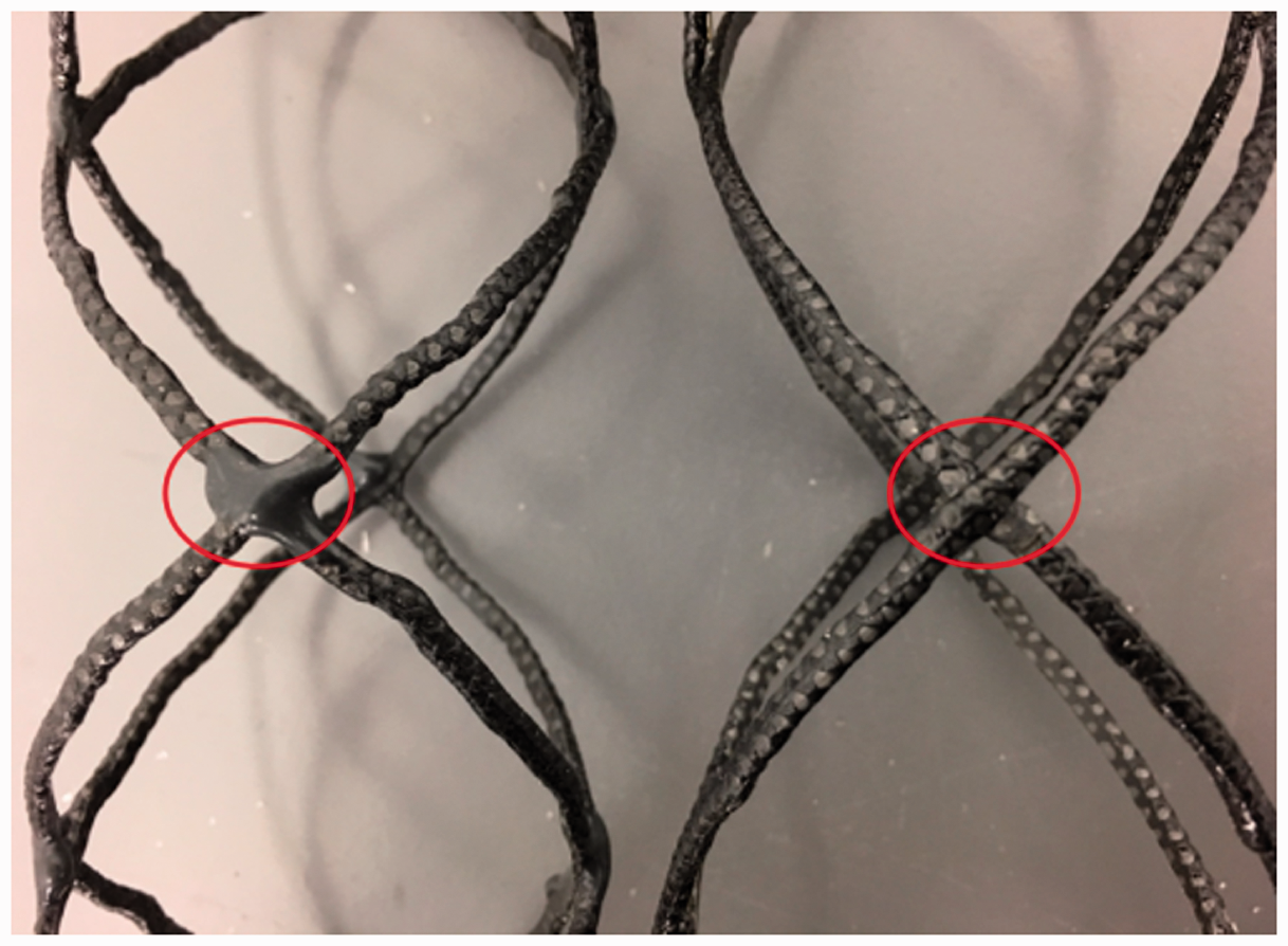
The loading pattern of braider yarns on the 64 carriers braiding machine and the representative 3D model of yarn motion are shown in Figure 2. The mandrel diameter was 45 mm. Three different braiding angles (35°, 45°, and 67.5°) were obtained by changing the take-up speed. The O-ACS samples are categorized into two groups: with no-bonding joints and with 3M® DP-420 epoxy bonded joints. The O-ACS samples without bonding joints were made by manually breaking all the joints, which were formed by the resin in the core, whereas the O-ACS samples with joints were made by adding extra 3M® DP-420 epoxy resin on the joint locations. The O-ACS samples with no joints and with DP-420 bonded joints are shown in Figure 3. Loading pattern of braider yarns on the 64 carriers braiding machine (a), and CAD representation of yarn motion (b). O-ACS samples with DP-420 bonded joints (left) and no joints (right).
Five specimens were prepared for each structure. One important consideration is that the O-ACS samples must be well aligned and clamped on the torsion tester in order to obtain valid results. Since there are no standard test procedures for this new lattice structure, a special alignment and fixture system was designed to ensure the precise alignment and orientation of the specimens on the torsion tester. The alignment system specifically designed for the O-ACS samples is shown in Figure 4. O-ACS sample alignment system for torsion tests.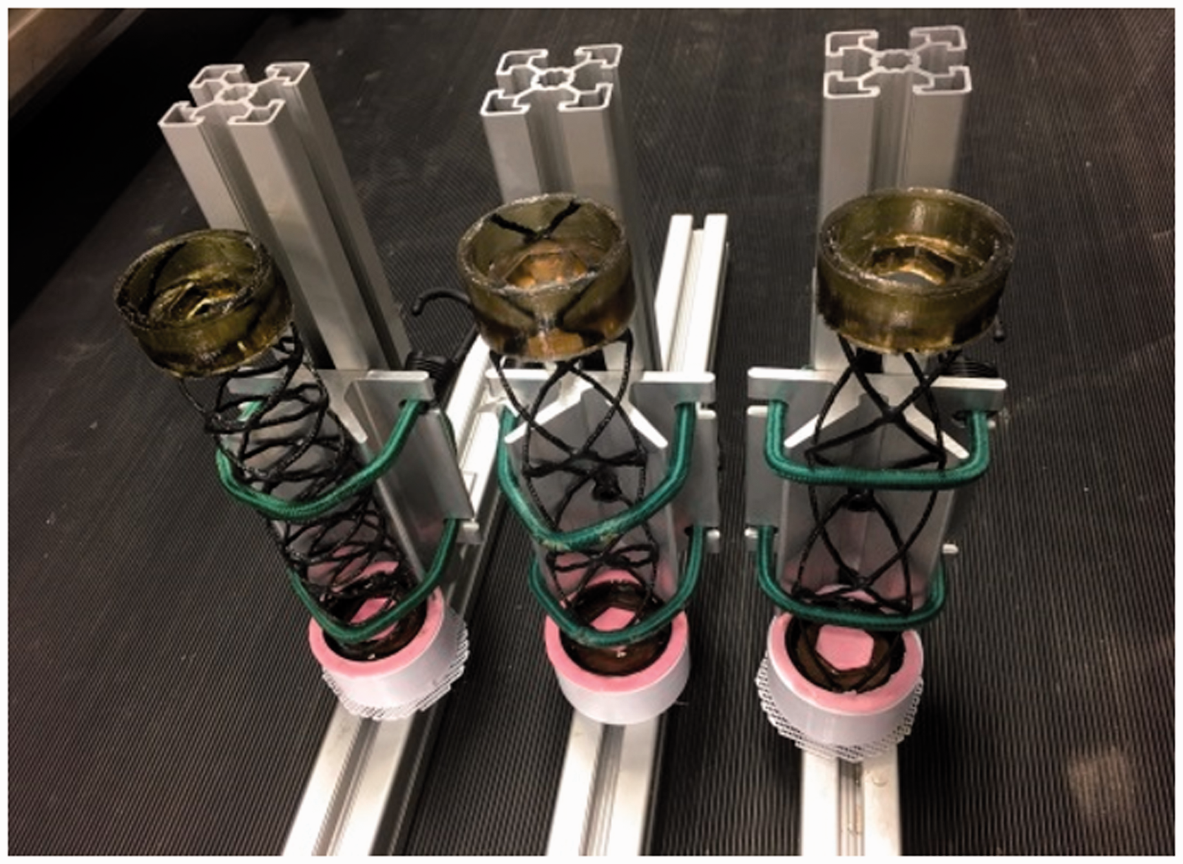
Two structural frames are mounted vertical to each other. A V-shape clamp, on which a hole is drilled at the center, is bolted on the centerline of the vertical frame. The O-ACS samples can be well aligned by tightening against the V-shape clamp with an elastic cord. A 3D-printed PLA (polylactic acid) cap is used to hold a female silicon mold on which the O-ACS is secured at the center of the mold. Casting resin can be poured into the silicon mold and easily peeled off after it is cured (Figure 5). This is essentially an alignment system with reusable flexible silicon molds that can significantly reduce the cycle time for sample preparation. The end-fitting fixture of the O-ACS samples for torsion testing is shown in Figure 5 as well. It has a hexagonal cavity into which a hexagonal rod can be inserted. Silicon cap mold for housing O-ACS ends (left) and end fixture of O-ACS for torsion tests.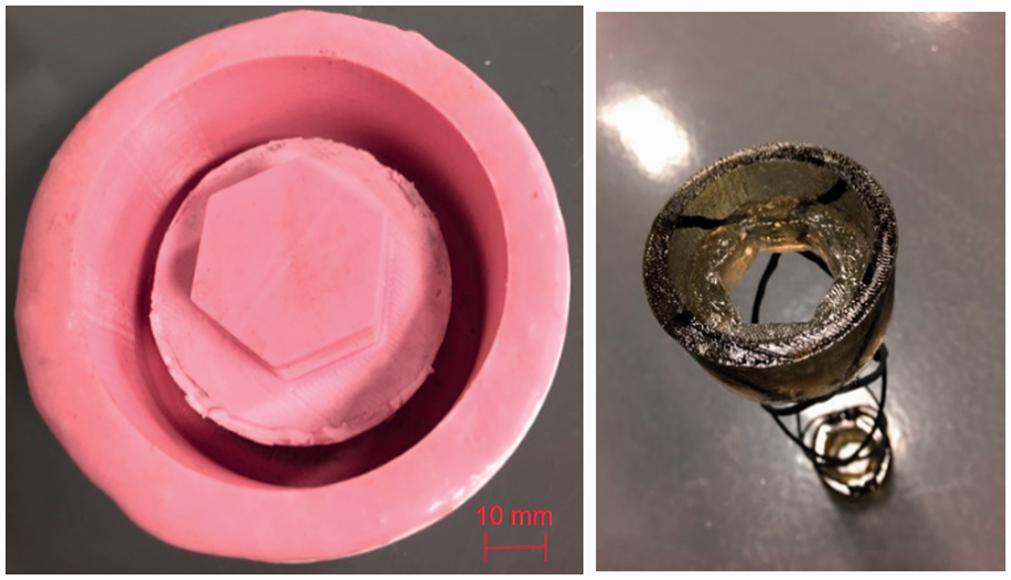
The final samples of different braiding angles with end fittings are shown in Figure 6 for no joints and with DP-420 bonded joints. The O-ACS samples were fixed on the torsion tester with two hexagonal rods as illustrated in Figure 7. All the samples had the same gauge length of 220 mm. The crosshead speed was 0.25°/s. O-ACS samples with no joint (left) and with DP-420 epoxy joint (right), with braiding angles of 35°, 45°, and 67.5° (from top to bottom). O-ACS torsion test sample with hexagons (left) and samples mounted on the torsion tester.

Finite element model
The first step of the finite element model is to generate the 3D geometric model of the O-ACS samples. By the nature of the yarn components in the O-ACS, the 3D model can be established by beam elements. A general description of the geometrical model developed using kinematics was given earlier by two of the authors [8]. The structure manufactured and analyzed in this work has two clockwise cord-pregs and two counterclockwise cord-pregs. The kinematic equations of braiding are simplified as follows


Equations (1a), (1b), (1c) and (2a), (2b), (2c) represent the kinematics of clockwise traveling cord-pregs and the counterclockwise traveling cord-pregs, respectively. Then, a beam element is placed at the joint (intersecting location) to connect the two crossing tows. Schematic of a typical joint is shown in Figure 8. The 3D Timoshenko beam elements are used to simulate the behavior of O-ACS. The material properties, which were obtained from the experiments for carbon fiber composites, are given in Table 1. The finite element model is a linear and static model, which comprises of 3D Timoshenko beam elements. Mesh density is given in Figure 9 in which the rotation of the structure under the effect of 1 Nm torque is graphed as a function of the number of beam elements. Schematic of a joint represented by beam elements (shown in dark). Rotation versus mesh density. Material input properties for the cord-preg finite element model.


The stiffness of the spring joints was varied between 104 and 1010 (unit: N) to study the effect of the joint stiffness on the overall torsional stiffness of the structure. The rigid joint model can be achieved by defining a rigid element, which inhibits the relative motion between the two nodes at the intersection. The finite element analysis (FEA) is implemented in Python with VPython for visualization of the rigid joint mode [30]. The deformed and undeformed states of the O-ACS are given in Figure 10. Deformed (dark) and undeformed (light) state of the O-ACS structure.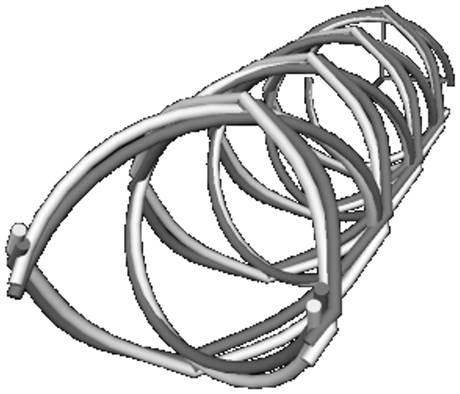
Results and discussion

Experimental data of the torsional stiffness for all samples.
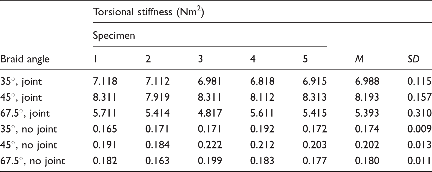
It can be concluded that the structures with the bonded joints are much stiffer than those without the bonded joints under torsion. The bonded joints increase the structural redundancy, which results in a stiffer structure. The sample with 45° braiding angle shows the highest torsional stiffness as expected.
Degree of redundancy (determinacy).

Structural redundancy affects the distribution of loads throughout the structure as the joints can transfer forces and moments. As the joint stiffness increases, less deformation takes place and more forces and moments are transferred. In the rigid joint case, the forces and moments are transferred completely with no relative motions between nodes at the joint, whereas flexible joint transfers less forces and moments due to larger relative motion between nodes at the joint. The lower and upper bounds can be determined by the no-joint and rigid joint case, respectively. That is, the stiffness of the structure is bound in this range and is predictable given a proper value of the joint stiffness. In order to predict the overall stiffness of the structure corresponding to a certain joint stiffness, an analytical model is established using the sigmoid function. The data points obtained from the FEA analysis can be used for curve fitting with a sigmoid model. The sigmoid function used is given in equation (4) (


The coefficients obtained from curve fitting are given in Table 4. The FEA results, sigmoid curve fitting, and experimental data are summarized in Figure 11. The FEA data can be well fitted with the sigmoid function. The experimental data also show good agreement with the FEA results. The structures with 45° braiding angle have the highest stiffness. The analysis indicates that the stiffness of the structure with DP-420 bonded joints does not reach the maximum stiffness derived from the rigid joints case. Therefore, the reinforcement of the joints would improve the overall torsional stiffness of the structure. Torsional stiffness versus joint stiffness for the FEA data, sigmoid fitting, and experimental data. Coefficients for the sigmoid model.

Figure 12 shows the relationship between torsional stiffness and normalized joint stiffness, which is the logarithm of the ratio of joints stiffness to cord-preg stiffness. The data points for each structure are plotted at −1, 0, and 1 which, by definition of logarithm at base 10, indicate the joint stiffness to be one-10th, equal to, and 10 times of the cord-preg stiffness, respectively. As shown in Figure 12, when the joint stiffness is 10 times the component (cord-preg) stiffness, 35°, 45°, and 67.5° structures exhibit 97%, 96%, and 93% of the maximum torsional stiffness, respectively, calculated when the joint is considered rigid. Structures with 35°, 45°, and 67.5° retain 81%, 72%, and 57% of the maximum torsional stiffness, respectively, when joint stiffness is equal to the component stiffness. At the vicinity where joint stiffness is only 10% of the component stiffness, the torsional stiffness of 35°, 45°, and 67.5° structures is degraded to 32%, 22%, and 13% of the maximum torsional stiffness, respectively. Torsional stiffness versus logarithm of joints' stiffness to cord-preg stiffness ratio.
Figure 12 provides a guideline about the structural stiffness level of a sparse lattice structure (like O-ACS) based on the chemically bonded joints. A joint stiffness that is 10 times the component stiffness seems to be enough for the overall stiffness to be over 90% of the stiffness that would be attained with rigid joints. However, the chemical bonding itself provided by the towpreg is far from reaching this goal. Therefore, other techniques such as encapsulating the whole joint with more resin may be needed. Another perspective regarding the redundancy of the structure is that the overall torsional stiffness is associated with the structural redundancy, which is a function of the joint stiffness (Table 3). When the lattice structure is dense structure rather than a sparse one, meaning having more components and joints in the repeating unit, the degree of redundancy is increased. Therefore, one way to reduce the overall torsional stiffness degradation is to design a dense lattice structure where the degree of redundancy is increased by increasing the number of components and joints such that the requirement for joint stiffness is downgraded to a more reasonable and approachable value.
Conclusions
In this work, a finite element model is developed to predict the torsional stiffness of braided open lattice structures with different braiding angles and varying joint stiffness. The finite element model is validated using the experimental results. The analysis shows that the joint stiffness has significant effect on the overall torsional stiffness of the structure, which has a lower and upper bound based on having no joint or rigid joints, respectively. A closed-form equation for the overall stiffness and the joint stiffness is proposed using a sigmoid function. The bonded joints are important to minimize overall stiffness degradation for open lattice structures, especially for sparse lattice structures.
The weakness of the joint can be mitigated by forming a larger bonding surface, or interlacing small towpregs multiple times to form many bonding surfaces rather than just one. In O-ACS structures, there are only two relatively large tows interlacing to form one bonding. Based on this analysis, to increase the ability of a relatively sparse structure such as O-ACS to resist torsion, the stiffness of the joints needs to be 10 times higher than that of the structural component. This can be done in different ways. One is to increase the number of tows in O-ACS to form a dense structure rather than a sparse structure. By doing this, the redundancy in the structure will be increased which would reduce the effect of joint stiffness on the structure. Another way is to add stiffness to the joints such as applying extra resin to form a mega joint at the interlacing location.
Footnotes
Declaration of conflicting interests
The author(s) declared no potential conflicts of interest with respect to the research, authorship, and/or publication of this article.
Funding
The author(s) disclosed receipt of the following financial support for the research, authorship, and/or publication of this article: This work has been supported by NASA (Grant G00007992), Auburn University Intramural Grants Program (Grant 101502) and Highland Composites (gift money). The authors are grateful for the support provided.