
Abstract
The durability of the notch and un-notch composites is mainly affected by environmental ageing, the condition of mechanical loading and mechanical ageing. Due to the dissimilarity of two components of fibre mat-reinforced thermosetting composites (e.g. fibre and resin), thermal stress and strain can be generated and raised by moisture, temperature variation, thermal ageing and mechanical ageing in any working environment. This study aims at investigating the effect of thermal ageing fatigue and mechanical ageing fatigue on the mechanical durability and notch sensitivity properties of glass fibre mat unsaturated polyester resin composites and kenaf fibre mat/unsaturated polyester composites. Tensile tests of smooth and notched specimens, low cycle tensile fatigue tests, dynamic mechanical analysis, stress distribution by point-stress failure criteria and notch sensitivity analysis were performed to both types of the specimens. Both composites were previously taken under up to 100 number of freeze-thaw ageing cycles (from −25 to + 58℃). It is found that the tensile modulus and un-notched strength of kenaf fibre mat/unsaturated polyester were decreased by 30 and 27%, respectively, which was more severe than that of glass fibre mat/unsaturated polyester composites. After the thermal ageing, notch (open hole) did not diminish the strength property of kenaf fibre mat/unsaturated polyester, and there was an absolute increase of characteristic distance (d0) which indicates the lower notch sensitivity of kenaf fibre mat/unsaturated polyester. Although glass fibre mat/unsaturated polyester had superior mechanical properties, after thermal ageing, while kenaf fibre mat/unsaturated polyester presented stable low cycle fatigue property, better energy absorption and notch sensitivity properties.
Introduction
Fibre-reinforced composites present an excellent potential for automobile and other applications due to the high specific strength, stiffness and anti-rust even in relatively rough environments [1–4]. The longstanding mechanical properties of the organic matrix composites depend on many factors such as water immersion, salt and alkaline solutions, high and low temperatures, moisture and freeze-heating cycles [1,2,5–8]. Thermal ageing with open-air moisture is one of the most relevant types of an environmental agent for which composite materials are subjected to outdoor applications such as automobiles [1,9].
Some of the studies have been carried out so far on the thermal ageing fatigue to investigate the extreme temperature effect, for instance, Dutta and Hui [3] showed the variation on flexural properties suffered by two different glass fibre composites made of isophthalic polyester resin after being exposed to the thermal cycles (TCs) between −60 and 50℃. The glass composite specimens endured 6.2% Young's modulus and 6.3% shear modulus degradation after bearing TCs and also exhibited extensive cracks in the interior of the composites. The cryogenic temperature probably causes the cracks in the composites. Some studies focused on the dry weather effect, as Sousa et al. [4] described the glass fibre-reinforced profiles of unsaturated polyester (UP) and vinyl ester (VE) which were exposed to a Mediterranean range of thermal variations (−5 to 40℃) for up to 190 cycles in a dry condition. The UP profiles presented that tensile, flexural and inter-laminar shear strengths decreased by 13, 11 and 11%, respectively, without any crack, whereas VE profiles showed comparatively better resisting properties against TCs. In recent work, Ghasemi et al. [10] emphasised on the hole size effect during thermal cycling that after 250 TC (0–100℃) of glass/epoxy composites 3–6% of notched strength decreased with the higher number of TCs and larger hole size. This work did not present any data on notch sensitivity and mechanical fatigue.
However, as mentioned above, most of the reports of thermal ageing analysis were on high-performance synthetic fibre such as glass fibre, carbon fibre and basalt fibre-reinforced composites. There was no analysis found on notch sensitivity and mechanical ageing at the post thermal ageing of these composites.
On the other hand, the applications of natural fibres in composites are spreading widely in many industrial areas such as automobiles, furniture, packing construction and sports [11–15]. The most common natural plants used as reinforced fibres are bast fibres, such as hemp, jute, flax, kenaf and sisal due to their low cost, low density, less damage to the processing equipment and excellent relative mechanical properties [16–20]. Kenaf has been found to be the essential raw material for composites among all the natural fibres [21,22]. However, it is deplorable that there are very few works found on environmental ageing effects on the kenaf mat composites [23]. Among them, no significant reports are dealing with notch sensitivity with combined thermal and mechanical ageing effects of kenaf fibre composites, which was necessary to evaluate the working environment correctly for the right application of the natural fibre composites. As the application of the natural composites in automobiles is being increased, similar to the high-performance materials, researches are needed to be accomplished to study on the effects of combined environmental and mechanical factors such as thermal ageing, tensile stress, low cycle fatigue (LCF), notch sensitivity and their stress distribution of the kenaf fibre composites.
Herein, there are no significant studies addressing notch sensitivity with combined thermal and mechanical ageing effects of fibre mat composites. This study was formulated to find out how the thermal fatigue ageing with open-air moisture affects notch sensitivity, thermal, mechanical, physical and fatigue properties of the kenaf fibre mat/UP composite (KM/UP) compared to the glass fibre mat/UP composite (GM/UP). The UP composites have several advantages over other counter composites. It has smart use in lightweight automobile application with low moisture absorption, excellent adhesion between the fibre and the matrix [24]. The UP resin was considered appropriate in this research. The thermal ageing was designed up to 100 cycles with a typical extreme environmental temperature range from −25 to + 58℃ for automobiles assuming the approximate approaching thermal boundary of the earth concerning the global warming issue. The paper described the maximum changes after thermal ageing in the microstructure of the composites, thermal properties and the mechanical properties such as LCF, notch sensitivity, energy absorption and some of the physical properties. The complementary output provided by the finite element method for stress distribution was also presented.
Methods
Materials and fabrication
E-GM (Nitto Glasstex Co., Ltd.) was used as chopped bundles of 5-cm length fibres (average diameter 13 µm) which were combined by thermoplastic glue with a density of 450 g/m3. On the other hand, KM with 6-cm length fibres (average diameter 64 µm), punched mat purchased from PANASONIC company, was used with an average fibre's density of 1.157 g/cm3 and unit area weight of 542 g/m2. UP resin (Showa: RIGORAC 150 HRBQNTNW), with a density of 1.25 g/cm3 and Young's modulus of 3.2 GPa, tensile strength 42 MPa and elongation at break 2.18%, was used as the matrix for both fibre mats. The UP was mixed with the hardener MEKPO (methyl ethyl ketone peroxide) (from PERMEK N; NOF Corporation), maintaining the ratio of 100:0.7. Composites were fabricated by hand lay-up moulding followed by compression method. Five layers of GMs were laid over the resin one by one after immersion of each layer. For the reduction of voids, an autoclave with vacuum evacuation was applied to the resin-impregnated kenaf mat. Both impregnated fibre mats were kept under 100 kg of deadweight plates to be cured for 24 h at room temperature, and then they were dried at 100℃ for 2 h in order to post cure. The thickness of the composites was controlled by using spacers to get the average volume fraction of the fibre composites. The fabrication of GM/UP and KM/UP in the same fibre volume fraction with closely similar thickness was insuperably complicated by this fabrication method due to the fluffiness and higher average fibre diameter of kenaf fibres. The average fibre volume fraction of GM/UP was 19.62%, and for KM/UP, it was 10.51%. Both composite specimens, along with the fibre mats, are shown in Figure 1.
(a) GM; (b) KM; (c) un-notched and notched specimens of KM/UP; (d) un-notched specimen of GM/UP in the tensile testing gripping clamps with an extensometer; (e) notched specimens of GM/UP with attached aluminium tabs; (f) drilling machine used for making an open hole; and (g) heating and freezing thermal ageing profile for GM/UP and KM/UP.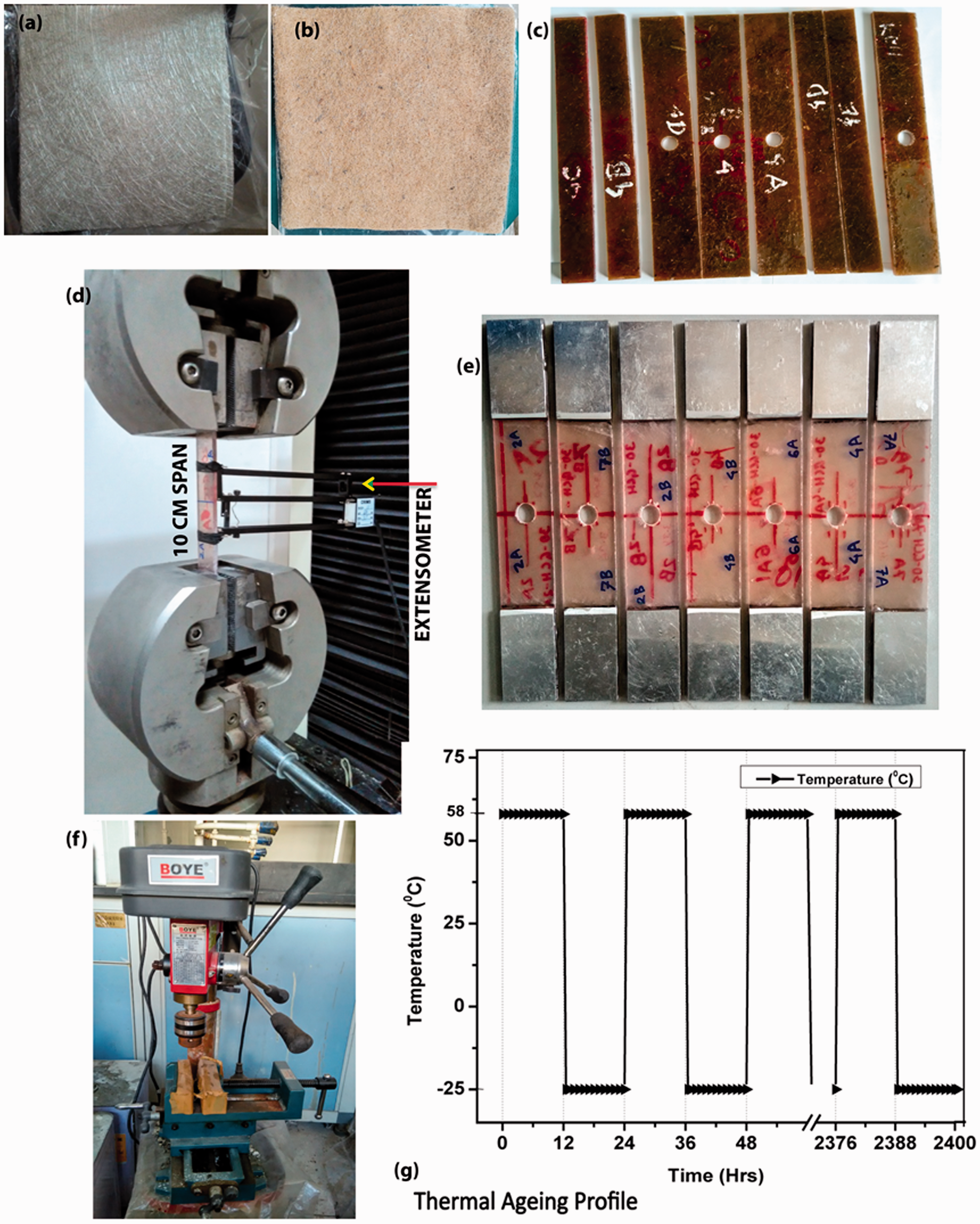
Experimental procedure
The tensile specimens were prepared according to the ASTM D790 standard. At least six specimens were prepared for each set of condition. The dimension of the un-notched and notched (with an open hole) specimens along with the span of 100 mm was, respectively, (200 × 20) mm and (200 × 30) mm. In order to prepare the notched specimen, about 10 mm holes were drilled in the geometric centre of the specimens by using the drill machine (Drill Press Bench Type) from BOYE company at a speed of 1250 rotation/min with wood support. The drill machine is shown in Figure 1(f). The specimen width and hole diameter ratio were about three for both composites. Un-notched and notched specimens are shown in Figure 1(c) and (e).
Tensile testing was performed with an Instron Universal Testing machine at a speed of 1 mm/min under standard laboratory atmospheric conditions (temperature: 23 ± 3℃; relative humidity: 50 ± 10%) according to ASTM D3039. To figure out the accurate tensile strain and modulus, an extensometer was employed in the middle of the un-notched specimens gripped by two tensile test clamps; see Figure 1(d). The recorded repetition of the experiment data was from four to five times.
The environmental ageing was limited up to 100 times of controlled humid thermal cycling where each of which was figured by keeping one set of the specimen in dry condition first at a 58 ± 2℃ temperature in an oven for 12 h, then taking them out instantly and keeping in a freezer at −25 ± 2℃ for 12 h. Two environmental factors worked for this environmental ageing, e.g. temperature and moisture. The temperature was measured by ‘Type K’ DM6902 thermocouples (Shenzhen Victor Hi-Tech Co., Ltd) attached to the specimen surface or the surroundings. The ageing profile is shown clearly in Figure 1(g). The effect of moisture in the composites is incorporated in the ‘Results and discussion’ section.
LCF test was carried out up to 30 fatigue cycles where the stress arrived at a 50–55% pre-set load of the corresponding maximum tensile load to observe the least mechanical fatigue response of the KM/UP and the GM/UP after environmental ageing. Furthermore, the fatigue property of KM/UP of this study was compared with the work of Hojo et al. [8]. After the LCF test, specimens were stretched to fracture.
Notch strength and sensitivity
For the specimen with a hole, notched strength was calculated by the following formula
The notch sensitivity of a material is defined as a measure which represents how sensitive a material is to the notches or geometric discontinuities. Notch sensitivity increases with the decreasing value of notch sensitivity indicator ‘η’ which can be defined as

There is a strong relationship between notch sensitivity and the characteristic distance of the notched specimen. The characteristic distance can be obtained according to the point stress criteria. In the point-stress failure criteria, the characteristic distance (d0) is the length from the hole edge to the point where the stress equals to un-notched strength when the notched specimen carries the maximum load. It could be used to evaluate the sensitivity of composites to a circular open hole [26,27]. The higher notch sensitivity refers to the lower characteristic distance of the composites [28].
In this study, the stress distribution of the notched specimen during fracture was analysed by finite element method (MSC-Marc software). In the simulation, the linear elasticity method was used for the composites as they were considered as isotropic. 2D triangle plane element of three points (Element type 6) was considered suitable for both composites. The maximum tensile load at the breaking area for the notch specimens during the tensile test together with the modulus was employed for the analysis of the stress distribution around the open hole. The simulated test was very close to the tensile testing. The finer elements were meshed near the open-drilled hole for obtaining more accurate results. Then, from the stress distribution, the characteristic distance was calculated. The method is described more evidently in the Supplementary section (Figure S1). The characteristic distance is the indicator of the notch sensitivity of materials, which is explained in the ‘Discussion’ section too.
Cross-sectional observation of the fracture area was carried out on the selected test specimens by scanning electron microscope (TM3000) at an accelerating voltage of 5 kV with a focus on the failure mechanism.
Dynamic mechanical analysis tests were conducted using a Perkin Elmer; DMA7e analyser with extension (15 mm × 5 mm × 1 mm) type clamp at a constant frequency of 1 Hz to analyse the viscoelastic behaviour of the composites as well as to assess the glass transition temperature variation. The analysis was carried out from room temperature up to 200℃ at a rate of 5℃/min. Three specimens were tested for each thermal ageing set.
Results and discussion
Influence of the environmental ageing on the mechanical properties
Despite the different volume fraction and strength of the fibre in two composites, considering the similar fabrication method, similar resin system of the composites and similar random fibre orientation, the mechanical and physical properties of them were compared and discussed. Besides, the discussion in this part was not emphasised exclusively on the degradation property of UP resin by the thermal ageing, instead focused on the different reinforcement forms, i.e. kenaf mat and glass mat.
Mechanical properties of GM/UP.

Mechanical properties of KM/UP.
Typical tensile stress–strain curves of GM/UP and KM/UP are shown in Figure 2(a). The tensile stress continued escalation with the non-linear strain progression until the final and maximum load reached to the point of rupture. Here, the ultimate stress and breaking strength are almost the same. Although the maximum stress and strain of the two composites are different, they have similarity yet in their tensile performance.
(a) Typical stress–strain curve of GM/UP and KM/UP and (b) average tensile strength (un-notched) and average notched strength of GM/UP and KM/UP composites together at different thermal cycling stage.
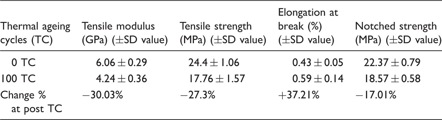
The average tensile modulus of GM/UP and KM/UP at different thermal ageing cycle is presented in Tables 1 and 2 wherein KM/UP, the tensile modulus decreased more than in GM/UP. The total decrement of modulus after 100 environmental cycles was about 13% in GM/UP and 30% in KM/UP.
Tables 1 and 2 described the rising of the elongation at break in both GM/UP and KM/UP at post thermal ageing cycles. After 100 cycles, both composites showed nearly the same increment of elongation at break, which was 34% in GM/UP and 37% in KM/UP as compared to the non-degraded ones. However, the average tensile elongation at break (un-notched) of GM/UP was much higher than KM/UP due to the more prominent elongation properties of glass fibre as compared to the kenaf fibre [14,22]. The decreasing trend of modulus and increasing trend of elongation at break (%) were observed at post-TCs due to the fatigue effects of thermal ageing which caused the loss of adhesion properties of fibres from the resin polymer.
The tensile strength (un-notched) of GM/UP and KM/UP at different thermal ageing cycles is shown in Figure 2(b) and Tables 1 and 2. After 100 cycles, the average tensile strength decreased by 14% in GM/UP and 27% in KM/UP. All of these properties change happened due to the probable stress caused by the different value of the fibre and matrix expansion during thermal ageing. The stress caused by such strain can lead to the change of the mentioned mechanical properties. Furthermore, the significant temperature changes in thermal ageing can cause more compressive and tensile stresses and contribute to the thermal fatigue of the composites [9,29–31]. The internal inter-facial small strain in the matrix during thermal ageing may be the reason for the modulus change [32].
Regarding notched strengths of GM/UP and KM/UP, they decreased at different stages of thermal ageing. Although glass fibre is stronger than kenaf fibre, after 100 cycles, both composites delivered almost the same rate of notched strength drop (about 17%). Furthermore, it can be observed in Figure 2(b) that at every definite cycle, average notched strength of GM/UP differs a lot from un-notched strength (on average 12%) due to the stress concentration. However, in the case of KM/UP, the notched strength was almost near to the un-notched strength at every cycle after just 30 cycles. So, here, it can be concluded from those tables and Figure 2(b) that after the specified number of thermal ageing, cycle notch (making a hole) could not subside the strength property of KM/UP. Instead, the KM/UP showed the improved notched strength properties compared to GM/UP. The SEM observation can explain the ground behind these above phenomena.
SEM observation
The SEM micrographs of un-notched and notched GM/UP specimen after tensile failure at different TCs were shown in Figure 3. In 0 TC micrographs, there was a relatively smoother surface without much pulled out fibre and better interface of fibre with matrix than the post thermal micrographs. Regarding 30 and 100 TC micrographs, the fibres were randomly distributed in the matrix, and a clear pull-out, detached and de-bonding of some of the fibres can be seen.
SEM observation of (a, c, and e) un-notched specimens and (b, d, and f) notched specimens after tensile failure at different TCs of GM/UP.
In GM/UP, notched tensile fracture photographs showed more intensive polymer crack and interface degradation than un-notched specimen tensile fracture. This phenomenon proved that the more tensile strength loss happened after 100 thermal ageing cycles of notched specimens.
The pre-thermal (0 TC) and post-thermal cycle (30 and 100 TC) micrographs after tensile failure in both un-notched and notched specimens of KM/UP were shown in Figure 4. There have large smooth zones together with isolated broken fibres and better interface of fibre with the matrix in 0 TC micrographs.
SEM observation of (a, c, and e) un-notched specimens and (b, d, and f) notched specimens after tensile failure at different TCs of KM/UP.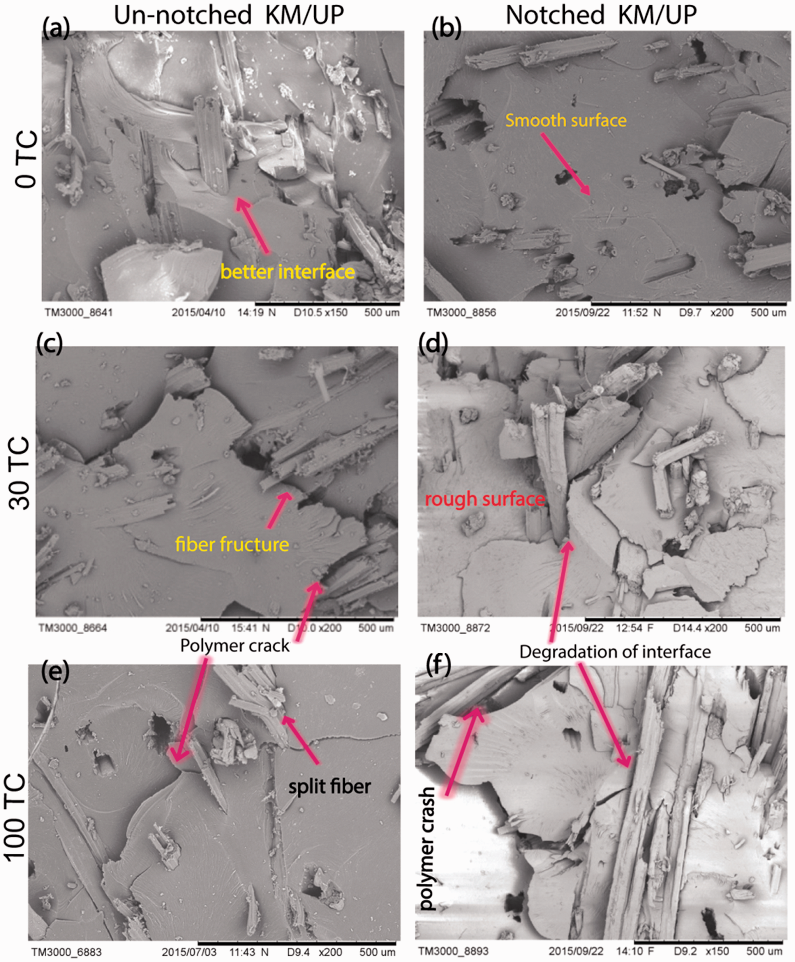
In KM/UP, notched and un-notched specimens showed a similar type of fracture nature which referred a similarity in tensile property drop of notched and un-notched specimens at 30 and 100 TC. After 30 TC, notched and un-notched strengths were almost equal at each cycling stage. Thus, the effect of the notch on the tensile strength of KM/UP was found to be very negligible in TCs.
The post-thermal specimen micrographs showed more cracks and de-bonding of fibres in all cases of tensile fracture and thus showed lower tensile strength and modulus at post thermal ageing cycles of both GM/UP and KM/UP than that of pre-thermal ageing. Both materials showed the same type of fracture surface at notched fracture stage after 30 and 100 TC. Due to this, their property deterioration, such as notch strength dropping (17%), happened almost the same way.
In thermal ageing, stresses develop in the polymer within the fibre–matrix interface region owing to the difference in the coefficients of thermal expansion of the two components which can bring micro-cracks in the matrix around the fibres and lead to the de-bonding of fibres from the matrix [33]. Micro-cracking also contributed to the change of mechanical properties of GM/UP and KM/UP composites [30,34]. The high sensitivity to temperature change is attributed to the thermal stress concentration located close to the surface of the fibre–matrix interface [1,35].
On the surface of both composites, the micro-cracks were found after 100 cycles of thermal ageing. The SEM images in Figure 5 of GM/UP and KM/UP specimen presented de-bonding of fibre from the matrix after completing thermal ageing. Both composites showed surface cracks in close range view.
SEM photographs of micro-crack on the surface of composites after 100 thermal ageing cycles: (a) fibre matrix debonding micro-crack in GM/UP, (b) fibre-matrix debonding in KM/UP and (c and d) micro-crack in the resin of KM/UP.
Influence of LCF test on the mechanical properties
LCF test was carried out to observe the cyclic fatigue behaviour of the fibre-reinforced composites after thermal ageing. In Table 3 and Figure 6(a), the summary of tensile modulus was presented during the LCF test by calculating every three times. The curves revealed that the tensile modulus of GM/UP before the LCF test (non-LCF) was 10.13 GPa, and it was around 9.0 GPa during the fatigue test at non-thermal ageing cycle (pre TC) with a CV% of 3.06%. At 30 TC and after 100 TC, the non-LCF modulus and during LCF test the modulus in every cycle was also around 9.0 GPa with the low value of CV% under 2.5% which suggests that modulus stay steady during these two LCF test. The tensile modulus was slightly affected by 30 cycles of the LCF test with 50–55% preset load. Moreover, the modulus variation and changing rate at post-thermal ageing decreased much compared to the pre-thermal ageing LCF.
Tensile modulus variation during LCF test and comparison with the original modulus at the different thermal ageing stage of (a) GM/UP and (b) KM/UP, where TC is thermal cycle; (c) Tensile modulus during LCF test and comparison with the original modulus of composites. It is Figure 6 of Hojo et al. [8]. Tensile modulus of the LCF test for GM/UP and KM/UP at different TCs.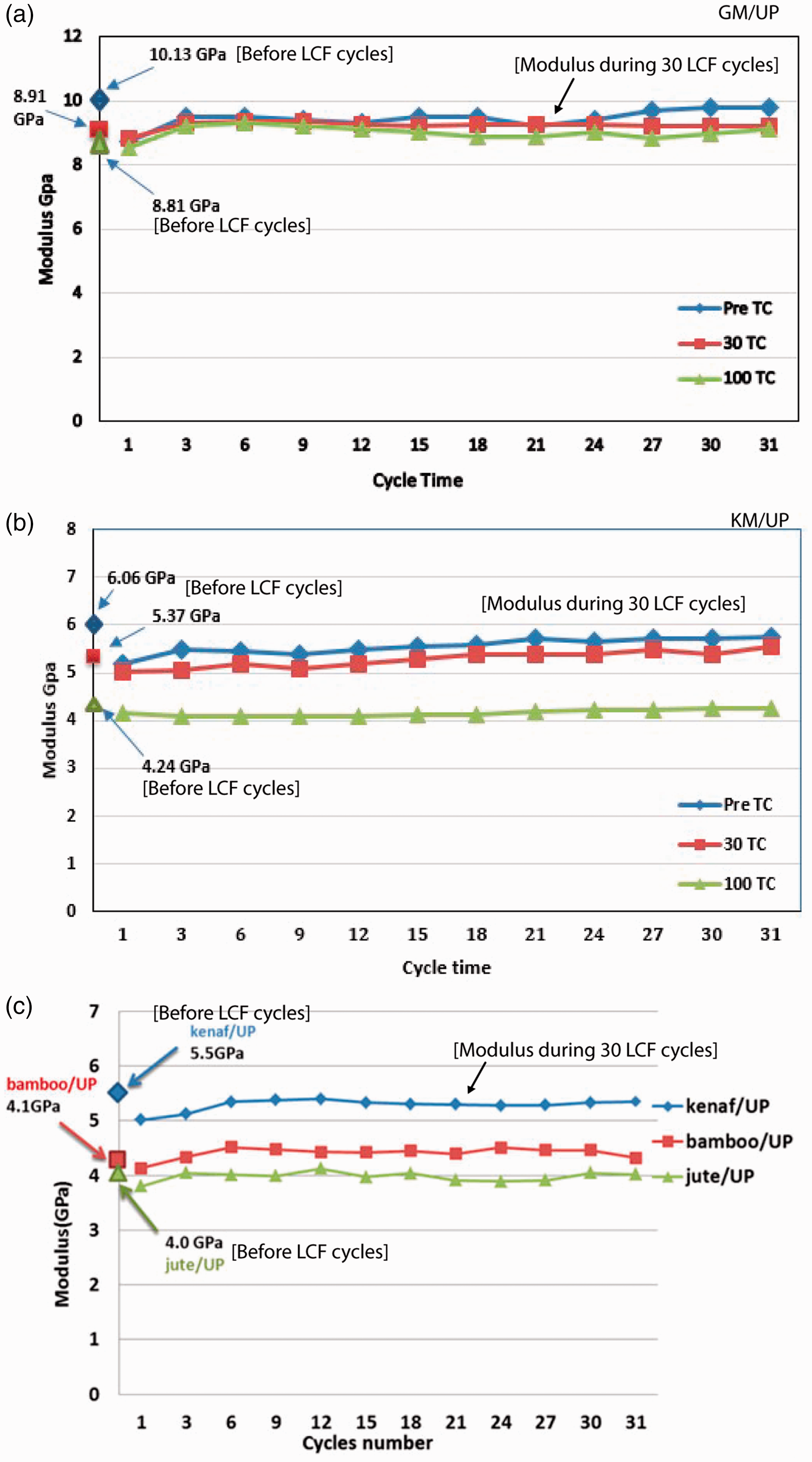
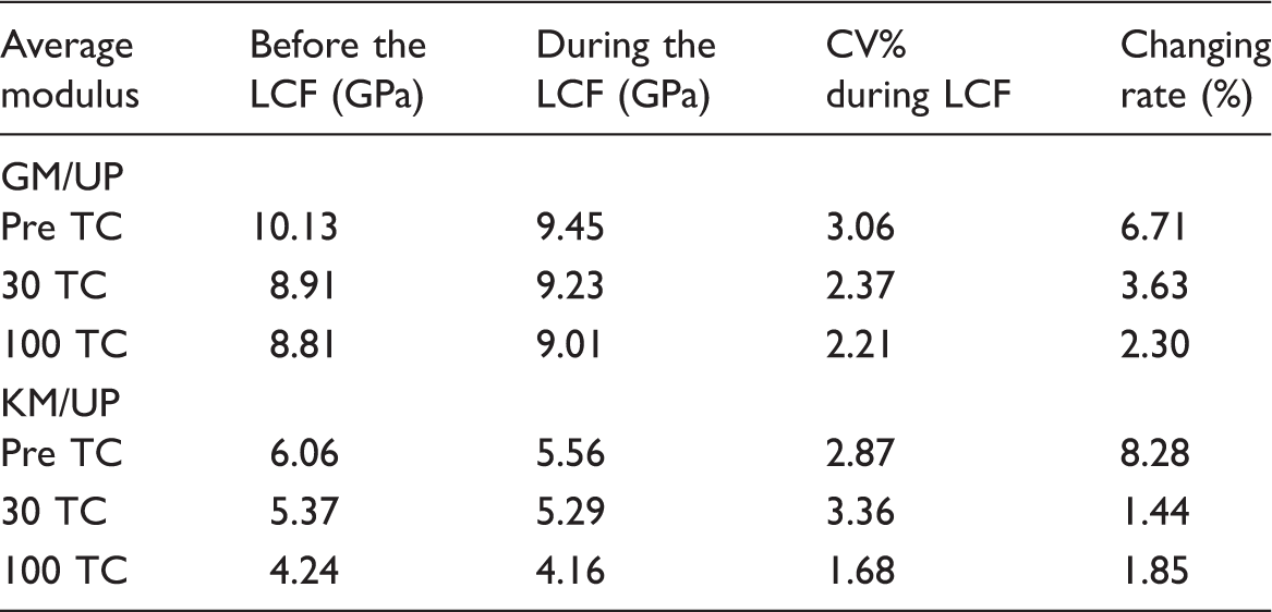
Figure 6(b) along with Table 3 presented the tensile modulus of KM/UP before and during the LCF fatigue test. Although the non-LCF modulus of pre TC was 6.06 GPa during the LCF test, the modulus was around 5.5 GPa at pre TC as well as 30 TC, while at 100 TC, the modulus before and during the LCF test was around 4.0 GPa. The graph denoted here that the 30 LCF cycles with 50–55% preset load slightly affected the modulus variation during LCF test.
If the modulus variation of KM/UP during LCF test is compared with the kenaf/UP part of Hojo [8] in Figure 6(c) as these two works followed the similar fabrication method, then the similarity can be found only with the Pre TC modulus variation line and modulus unit heights.
However, the modulus variation, changing rate and modulus unit heights during LCF cycles of 100 TC for both composites were lower than that of other cycling stages. KM/UP showed lower modulus variation and changing rate in contrast to GM/UP at post thermal ageing, which indicates that the kenaf fibre composites have better and more stable tensile anti-fatigue properties after thermal ageing. So, it can be concluded that a higher number of the thermal ageing cycle can make the least modulus variation and modulus changing rate during the LCF test.
After the LCF test, the tensile strength changing rate was around 5% at 100 TC for GM/UP specimen, which is shown in Figure 7(a). Similarly, in Figure 7(b), in case of KM/UP after LCF test, tensile strength changing rate at 100 TC was around 4.5% which was minimal change compared to the pre-thermal ageing stages. In both composites, after thermal ageing, 30 cycles of the LCF test with 50–55% preset load could not make a significant effect on the tensile strength changing rate. However, in the case of higher thermal ageing cycles, the strength changing rate in LCF test is also higher for both composites.
Tensile strength change% after LCF test at different thermal ageing cycles of (a) GM/UP and (b) KM/UP where error bar is representing the standard deviation.
For looking out more into the tendency of tensile performance during and after the LCF test, the stress–strain curves were recorded and presented in Figure 8. During the LCF of GM/UP at 0 and 100 TC, only the initial S–S curve of 30 LCF cycles shows little difference than other curves. The post LCF S–S curve is among all the LCF curves, which suggests the 30 LCF cycles with 50–55% preset load could not make an intense effect on GM/UP at 100 TC. The similar phenomena also happen for KM/UP with a little difference at 100 TC, the strain decreased and the S–S curve became more linear at post LCF which suggests that KM/UP became stiffer after thermal ageing. Dynamic mechanical analysis can explain more of this behaviour of KM/UP.
Stress–strain curves during and after 30 LCF cycles for GM/UP at (a) pre-thermal ageing (0 TC) and (b) post-thermal ageing (100 TC); and for KM/UP at (c) pre-thermal ageing (0 TC) and (d) post-thermal ageing (100 TC).
The tensile stress–time curve of LCF test can demonstrate each cycle individually, which can help to comprehend more of the tensile fatigue behaviour of the composites. The tensile stress–time curves during and after 30 LCF cycles for GM/UP and KM/UP at the different thermal ageing stages are presented in the Supplementary section (Figures S2 and S3).
The notched specimens during tensile test receive concentrated stress in the notched region. The extensometer is not suitable to record the notched strain. The displacement of the total span length is taken under consideration to develop the notched stress–displacement (NS–D) curve in order to observe propensity of the tensile property during the LCF test. The NS–D curves and NS-time curves during the LCF test of GM/UP and KM/UP at thermal ageing conditions are introduced in Figures S4 to S7 of the Supplementary section. In the NS–D curves, the displacement increases in the following LCF cycles with the corresponding preset load due to the unrecoverable fracture happens when the load exceeds the elastic level.
Weight change in thermal ageing
Weight change in thermal ageing.

The KM/UP presented a little bit more weight reduction due to the comparative higher moisture regains and moisture content of KM. The environmental ageing was carried out with available environmental moisture and air. As the temperature range of the ageing was less than the glass transition temperature of the UP resin, not of any chemical reaction happened during the cycling period that could harm the chemical network of polymer and cause more weight reduction [5,36].
Dynamic mechanical analysis
In Figure 9(a), tan δ – temperature curves of GM/UP at different thermal ageing cycles depicted that the glass transition temperature (Tg) shifted approximately 14 ° after thermal ageing. The tan δ lines showed peaks at 157.58, 150.69 and 143.72℃, respectively, for 0, 30 and 100 TC specimens. These curves described that after thermal ageing, the thermal properties of GM/UP altered and dropped down to a new transition temperature stage as well as lose their working temperature. After thermal ageing, the Tg changed significantly (9%), which could affect the thermal and mechanical properties of the composites [37–39]. The decrement of Tg is the consequence of thermal cycling ageing effect, which can change the property or state of the material in a non-reversible way.
Tan δ – temperature curve of (a) GM/UP and (b) KM/UP at pre (0 TC) and post (30 and 100 TC) thermal ageing cycles.
For KM/UP, in Figure 9(b), tan δ – temperature curves at different TCs are presented, and the Tg is moved to approximately 12 ° (7%) after thermal ageing. Here, tan δ lines depicted peaks at 161.91, 154.15 and 150.08℃ for 0, 30 and 100 TC specimens accordingly. In these curves, it was also clear that after thermal ageing, the properties of KM/UP set down to a new transition temperature stage.
In DMA, as Tg of both composites (157.6 and 161.9℃) are close, the polymer matrices in both composites are in the same state. The change of Tg after the thermal cycling of composites is also similar: −6.9 and –7.8℃ after 30 cycles, and −13.9 and –11.8℃ after 100 cycles for GM/UP and KM/UP, respectively. So, the change of matrix state in the composites during their thermal cycling is very similar. A difference in changes of mechanical properties during thermal cycling is found due to the difference in nature of reinforcing fibres as well as a difference in fibre volume content.
In the case of GM/UP, the tan δ peak moved down at 30 and 100 TC state. However, in KM/UP, the tan δ (damping) peak moved up at post thermal cycle condition. This upward lift of tan δ peak value denoted that more energy could be absorbed by the post thermal ageing experienced KM/UP composites. The peak height of the Tg or tan δ indicates the damping intensity of the specimens, and it is related to the internal molecular motion and energy dissipation of the fibre/matrix interface [37–40]. From Figure 9(b), it is evident that KM/UP composites have the highest tan δ (damping) value indicating a large amount of energy dissipation and hence better damping properties in post thermal ageing stage. Broader tan δ curve denotes the increased cross link density, strength and less stiffness. Narrower tan δ of KM/UP after thermal ageing indicates the decreased strength of the interface between fibre and matrix.
The kenaf fibres are mainly composed of cellulose and hemi-cellulose. Where inside of the fibre structure, there is lumen at the core and between fibril to fibril, there are spaces that show fluffiness [14,41]. Due to this cause, the composite of KM may absorb energy in it in the form of energy dissipation. After the thermal ageing, the interfaces between fibre and matrix became weaker and gained more fullness all over the composite, which contributed to the internal energy absorption and showed more energy absorbing properties. It can be suggested that this property of KM/UP would be feasible to apply in automobile application for shock absorption purpose.
Characteristic distance and notch sensitivity
In the case of notch tensile stretch, a stress concentration may happen due to the reduction of active stress area in a location of an object near the area where notch was introduced. The material can be failed in mechanical loading through the distribution of stress after concentrated stress oversteps the material's cohesive strength. Stress distribution of the open hole notched composite specimen often describes sharply in terms of characteristic distance. When notched specimen experiences the maximum load, two points can be found on the line through the centre of the hole and perpendicular to the stretching way, where the stress is equal to the un-notch strength. The minimum distance from the edge of the hole to the point is defined as the characteristic distance [26,42]. In this research, the stress distribution was calculated by finite element method (MSC.Marc). The calculation result is shown in Figure 10 for GM/UP and KM/UP at different thermal ageing cycles.
Characteristic distance of various specimens at the notched tensile test of KM/UP and GM/UP composites after different TCs.
The characteristic distance (d0) of GM/UP at different thermal ageing stages remained almost similar, but in the case of KM/UP, the increased characteristic distances were found at the higher thermal cycling stages; after 100 cycles, the average characteristics distance (d0) of KM/UP increased by 45.15% (Figure 10). The characteristic distance (d0) found from the finite element method is the measure of notch sensitivity. Higher d0 indicates lower notch sensitivity [43]. The KM/UP is the least notch sensitive, and GM/UP has the highest notch sensitivity after thermal ageing. Also, a more precise explanation can be drawn in the following paragraph.
Notch sensitivity
Although there was the highest percentage of un-notched strength drops in KM/UP (about −30%) than GM/UP after thermal ageing, it did not give the highest notched strength change in KM/UP (recall Tables 1 and 2). That proposes that the thermal ageing effect was different for these two un-notched and notched composites. Therefore, the evaluation of the composites necessitates more notch sensitivity study. The notch sensitivity is reciprocally proportional to the ratio of the notched to un-notched strength (η). A higher ratio of notched to un-notched strength refers to lower notch sensitivity. The notch sensitivity of composites steps up with the stepping down the value of η and becomes completely non-sensitive when η reaches unity [43].
Figure 11 shows that 100 thermal ageing cycles could not make any significant effect on the GM/UP to reduce notch sensitivity. On the other hand, this number of TCs was enough to reduce the notch sensitivity of KM/UP composites. The notch sensitivity based on σn/ σun or η and the characteristic distances (d0) is substantially complying in case of the KM/UP. The orders of the notch sensitivity for different TCs in the above both cases follow almost the same trend. Although the notch sensitivity of GM/UP increased a little at the primary ageing cycles, it remained almost constant for all the thermal cycling conditions. From these phenomena, it can be concluded that the KM/UP specimens presented better performance to resist the hole effect after 100 TC. The lower notch sensitivity of the KM/UP at higher thermal ageing cycles thus showed better notch sensitivity properties due to their weaker adhesion and interface properties between the fibre and polymer after thermal ageing than GM/UP composites.
Notch sensitivity of GM/UP and KM/UP composites at definite TCs.
Conclusion
In this work, the environmental thermal ageing resistance of hand layup-compression moulding fabricated GM/UP and KM/UP composites was studied with a temperature ranging from −25 to + 58℃ which focuses on the typical extreme environmental thermal effects on the mechanical ageing, durability and notch sensitivity. The following points are drawn from the experiments and analysis.
The tensile modulus and un-notched strength of GM/UP decreased by 13 and 14%, respectively. Whereas, for KM/UP, they were decreased by 30 and 27% accordingly, which are serious than that of GM/UP. The notched strengths of both composites decreased by almost the same content (17%). At the definite number of thermal ageing cycle, the KM/UP portrayed improved notched strength properties compared to the GM/UP. KM/UP showed better and more stable tensile anti-fatigue properties after thermal ageing, while a higher number of thermal ageing cycle makes the least modulus variation and modulus changing rate during the LCF test. The test did not show a considerable variation of modulus and strength during 30 LCF cycles within 50–55% pre-set load for both composites. In the case of NS–D, the LCF test marked unrecoverable fracture in every fatigue cycle. The DMA analysis showed that the state of the polymer matrix in both composites was almost similar, and at post thermal cycling, the change of matrix state was also similar which described the ground of some mechanical properties shift. Moreover, the analysis manifested the better energy absorption properties of thermal-aged KM/UP. The stress distribution by FEM simulation illustrated the lower notch sensitivity of KM/UP than GM/UP at post-TCs. The thermal ageing exhibited a significant effect on the notch sensitivity of the anisotropic composites. The notch sensitivity based on the notched to un-notched strength and the characteristic distances (d0) presented almost the similar effect.
Finally, it can be outlined that after environmental ageing, considering the similar composite systems, kenaf mat composites demonstrated steady low cycle tensile fatigue property, comparable better energy absorption property, improved notched strength and sensitivity and superior resistance property against the hole effect compared to the Glass mat composites. Further study should be undertaken with a higher number of thermal ageing cycles and a higher number of LCF cycles with 70 to 85% preset load.
Supplemental Material
Supplemental material for Durability and notch sensitivity analysis of environmental ageing induced glass fibre mat and kenaf fibre mat-reinforced composites
Supplemental Material for Durability and notch sensitivity analysis of environmental ageing induced glass fibre mat and kenaf fibre mat-reinforced composites by Md Sohag Miah, Jianyong Yu, Yuqiu Yang, Hafeezullah Memon and Muhammad A Rashid in Journal of Industrial Textiles
Footnotes
Acknowledgements
The authors gratefully acknowledge the assistance of Prof. Hiroyuki Hamada, Dr. Zhiyuan Zhang of Kyoto Institute Technology, Japan; Defang Zhao, Lichao Yu, and Syed Rashedul Islam of Donghua University, China.
Declaration of conflicting interests
The author(s) declared no potential conflicts of interest concerning the research, authorship, and/or publication of this article.
Funding
The author(s) received no financial support for the research, authorship, and/or publication of this article.
References
Supplementary Material
Please find the following supplemental material available below.
For Open Access articles published under a Creative Commons License, all supplemental material carries the same license as the article it is associated with.
For non-Open Access articles published, all supplemental material carries a non-exclusive license, and permission requests for re-use of supplemental material or any part of supplemental material shall be sent directly to the copyright owner as specified in the copyright notice associated with the article.