
Abstract
Composite materials are known for their high stiffness and strength at lower weight as compared to conventional structural materials. Recently, there has been a growing interest in finding the new ways to decrease delamination failure, which is a life limiting factor of laminated composites. This review paper emphasizes on the effects of different reinforcement structures on mode I fracture toughness and possible ways to improve fracture toughness. A brief description on intrinsic and extrinsic mechanisms of crack growth has been discussed along with the earlier investigations and recent developments for mode I fracture toughness testing. Factors that affect the fracture toughness are also discussed. A brief knowledge of mode I fracture toughness of traditional and advanced fiber-reinforced composites is given, which could help researchers to understand fracture behaviors of composites and thus, it can help engineers to design composites with higher interlaminar strength.
Keywords
Introduction
The high specific modulus, also known as stiffness to weight ratio, of fiber-reinforced polymer composites (FRPCs) has resulted in the widespread use of these composites as key structural engineering materials in automotive, aerospace [1–3], marine, transportation, infrastructure, civil engineering applications [4–8] and motorsport industries [4,9,10]. Since, there has been an ever-increasing demand for composite materials and new materials are being introduced in the market frequently, so it is challenging to assess their properties in order to forecast service life and failure behaviors. The performance evaluation of the advanced reinforcing fibers (glass [11], carbon [12,13], Kevlar [14,15] and PBO (poly(p-phenylene-2, 6-benzobisoxazole) [16,17] fibers) and resins (Epoxy [18–21], vinyl ester [11], polyimide (PI) [22] and cyanate ester [23]) in final composite is necessary for their safe application.
Compared to other damage categories, delamination evolution is a dominant life-limiting failure mode for composite structures [13,24–28]. It may be introduced either during manufacturing or caused by damaging events during service, for example, impact damage [29,30], large hailstones [31,32] and bird strike events [33,34], thus, hampering structural integrity and durability [35,36]. Keeping in view the adverse impact of delamination on the composite structures, it is necessary to consider in structural design process as well as in verification testing, to ensure safe application with prolonged life of these composites.
Property which defines the ability of a material to resist fracture is known as fracture toughness [37,38]. It indicates the amount of stress required to propagate a pre-existing thin crack. Damage tolerance is the desired basic property for various structures depending upon the end application [39]. Durability is an economic life-cycle design concern, whereas, damage tolerance tells about the structure's ability to securely withstand flaws until these flaws are removed or fixed. Fracture toughness characterization of composites is still on the way of growth as compared to metals. Fracture toughness depends on many factors. Many researchers reported that in FRPCs, the performance of fibers depends on the reinforcement's architecture [13,28,40], which is discussed in the next sections. Hence, structural effects of reinforcement as well as effects of other factors (manufacturing process, loading type, loading rate and temperature) on interlaminar fracture toughness are worth studying. Furthermore, the knowledge of damage and its mechanism should be extended to design composites with higher interlaminar strength for longer life span.
Fracture toughness
Fracture toughness is a distinguished property for many structural designs and applications to ensure reliability [41,42]. The value of this property is typically denoted by the strain energy release rate (
In composites, strain energy release rate ( Various cracking modes for fracture toughness classification.
Modes of fracture
The manner in which a crack propagates through a material gives insight into the mode of fracture. Thus, there are different modes of fracture for these composite materials. Cracking mode I is considered to be the crack opening or tensile mode of delamination. It is the most common form of fracture failure as its motion is like pulling plies of material away from each other. The crack faces undergo opening displacements relative to one another as it propagates. The corresponding material property
Cracking mode II is the in-plane shear mode of delamination. A shear stress acts parallel to the plane of the crack and perpendicular to the crack front. This is classified by two separated plies of material sliding above each other in the path of crack growth. This cracking mode is less common than the crack opening tensile mode, but it is still relevant to designs where force is not particularly down the center of a structural component. In cracking mode III, known as tearing mode, a shear stress acts parallel to the plane of the crack and parallel to the crack front. This is also termed as out of plane shear mode.
Types of preform used in textile-reinforced polymer composites and their impact on fracture toughness
The high specific stiffness and strength of composites have been of great deal for their utilization in structures where higher weight is a life-threatening variable. Hence, the development of low weight yet high strength composites are used in aerospace [44,45] and defense fields [46]. The advanced textile fibers such as Dyneema, Kevlar, glass, carbon and Zylon are known for their outstanding performance in protective applications. The performance of textile fibers varies depending on their architecture when used as reinforcement in composites. Hence, mechanical characterization in different structural forms [13,47–49], under several static and dynamic loading situations, is the area of interest in recent years.
Laminated composites
Most of the FRPCs are made from laminates. Interlaminar delamination presents one of the most important life limiting failure mode that restricts their applications [5,8–10,28,50,51] especially in primary aircraft structures [4,52]. As reported by Tamuzs et al. [53], the critical energy release rate of laminated composites does not usually exceed from 0.2 to 0.4 kJ/m2. These composite materials show a worrying weakness towards the presence and development of cracks between the layers [10] especially in mode I loading. [40]
Delamination can be initiated due to the occurrence of flaws during fabrication process or produced in structural components during service due to interlaminar tension and shear. It may also develop due to a multiple factors such as impact of falling objects, structural discontinuities, free edge effects, differences in moisture and temperature [7,10]. The growth of delamination results in stiffness loss and could ultimately result in catastrophic failure [50,54,55]. Crack growth is a result of competition among micro structural intrinsic and extrinsic mechanisms. Intrinsic mechanisms perform in front of crack tip and promote crack evolution. Extrinsic mechanisms perform behind crack tip and impede crack evolution [56].
In fibre-reinforced composites, the intrinsic mechanisms are structural voids [57], material dislocation [58] or debonding [59,60] generated during manufacture or in-service. The shielding mechanism, also known as external mechanism, results from the closure traction between crack faces in the crack opening due to unbroken fibres or yarns and by deflection of crack path [13,61]. Extrinsic mechanisms give rise to resistive curve (R-curve) behaviour and thus, increase the force required for crack growth [13,28,62]. In this regard, various methods have been introduced to improve interlaminar strength [63]. Z-pinning [64–68], stitching [39,68–70], 3D weaving [71] and braiding [9,68] are popular methods to improve fracture toughness of textile composites. Advanced textile composites prepared by these technologies have shown good impact damage tolerance [72–74].
Stitched laminated composites
Some experimental studies have been conducted on stitched unidirectional or woven FRPC composites to find interlaminar delamination. It was found that the stitched FRPC laminates present significantly larger interlaminar toughness as compared to un-stitched laminates [4,74–79], and that an increase in stitch density caused an increase in mode I strain energy release rate [4,74–76]. A recent study [80] has been carried out on flax fiber-epoxy composite laminates to find the effect of stitching in-through-thickness direction on mode I fracture toughness. At least 10% improvement in fracture toughness at the lowest fraction of stitch fiber was reported.
But, it is problematic to stitch big and complex structures by using existing stitching machines. It requires automated, intricate multi-needle stitching machines, which are costly for composite manufacturers. Meanwhile, the in-plane yarns can be distorted or damaged because of stitching leaving a negative impact on the in-plane mechanical properties [4,75].
Knitted fabric composites
Mode I fracture studies performed on knitted composites reported that these composites have extraordinary fracture toughness properties, being their
Z-anchor-reinforced composites
Z-anchor (z-pinning) is a novel through-the-thickness reinforcement, which is used to improve the interlaminar strength of composite laminates [83–88]. In the z-anchor process, in-plane yarns are entangled each other by sticking with special needles as shown in Figure 2. Z-pinned composites have significantly higher mode I delamination resistance than two-dimensional (2D) equivalents [9,88–91]. Kusaka et al. [88] experimentally characterized the mode I interlaminar fracture behavior of z-anchor-reinforced composite laminates with different z-anchor densities. Mode I interlaminar fracture behavior of z-anchor-reinforced composite laminates increased almost linearly with the z-anchor density. Pingkarawat et al. [92] studied the effects of length, diameter and the volume content of z-pins on interlaminar fracture toughness. It was reported that fracture toughness increased with an increase in volume content and length of z-pins and by decrease in diameter. During crack propagation process, z-anchor reinforcement induced a large amount of fibers bridging resulting in the improvement of the mode I fracture toughness of composite laminate [88,92].
Z-pinned reinforced composite [87].
Interlaminar z-directional flock-fibers-reinforced composites
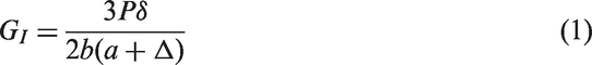
Another technique of manufacturing composites with greater delamination resistance is to introduce interlaminar z-directional flock-fibers [93]. Jia et al. carried out a study to compare the mechanical properties, specifically, the mode I fracture toughness of z-directional flock fiber-reinforced composite with 3D braided composites. It was reported that the (a) 3D braiding composite (b) z-directional flocked fibers-reinforced composite.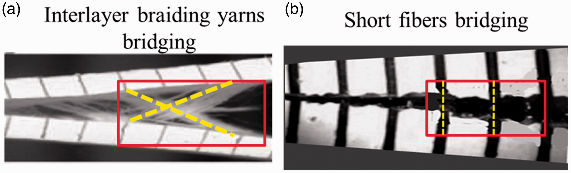
Chemical methods to improve fracture toughness of laminated composites
A common technique that has been adopted to improve the fracture toughness of laminated composites is to use toughened matrix material [39,94–97]. Later it was found that at higher temperatures, these resins show instability [50].
Another method to increase the interlaminar toughness of laminated composites is the addition of whiskers. In this regard, Yamashita et al. [98] and Sohn et al. [99] conducted experimental tests and found significant improvement in mode I fracture toughness of the composites. Wang et al. [4] also reported a significant improvement in mode I and mode II fracture toughness of CFRP laminates by dispensing whiskers at interface during the lay-up procedure. However, it was found that complications in the fabrication process and high cost are major hurdles in the practical application of this method [4].
Each of the above-mentioned methods proposed a way that can result in improved interlaminar fracture toughness and damage resistance. However, three-dimensional (3D) textile technologies are supposed to be the most effective ones. Numerous varieties of 3D fabrics have been developed which contribute distinctive features [5,9,13,100].
3D Woven textile composites
3D woven composites offer two major benefits compared to the 2D conventional laminated composites. Firstly, by altering warp and weft yarns, weave design, amount of binder, their mechanical properties can be customized to fulfill particular requirements without laminating [101,102]. Secondly and possibly more essentially, the z-yarns in through-thickness direction are interweaved with warp and weft yarns which prevent the growth of delamination [6] and increase post-impact mechanical properties [103]. In consideration of the angle of binder yarns, angle-interlock and orthogonal weaves can be identified as shown in Figure 4. In angle-interlock weave, binder tows are placed at an angle of θ < 90°, which is called undulation angle. In orthogonal-interlock weaves, the tows are placed at θ = 90°. When z-yarns are limited to an adjacent layer or a few layers, we call it layer-to-layer (or ply-to-ply) interlock weave [13], and when they go all the way through-the-thickness and interlace with all the layers, we call it through-thickness weave [105].
3D woven fabrics [104] (a) Orthogonal woven fabric. (b) Layer by layer angle interlock. (c) Through thickness angle interlock.
3D woven fabric composites have the ability to provide superior interlaminar fracture toughness and greater impact damage resistance than 2D conventional laminated composites [28,72,101,102]. Other desirable attributes include weight reduction, improved fatigue and fracture resistance and fully integrated assemblies.
3D woven composites are used for highly engineered applications such as I-Beams for civil infrastructure [106], multi-hit composite armor systems [107], aircraft frame work [105], leading edges of air craft wings [106] and engine fan blades of aircrafts [105,108]. For these applications, high through-thickness mechanical properties and damage tolerance are inevitable. Numerous experimental investigations on interlaminar toughness have been reported for 3D-reinforced composites [5,6,100]. Enhanced damage tolerance is attained due to bridging formation by z-binders in the crack wake. It impedes the growth of impact created damage, and thus minimizes the depletion of the post-impact properties [109]. It was found that a small volume content of binder yarns results in a big improvement to the damage tolerance [109,110].
3D Orthogonal inter-lock woven composites
Watanabe et al. [5] studied the interlaminar fracture toughness of 3D orthogonal interlocked fabric composites. They developed a numerical model for the characterization of delamination. The influence of through-thickness yarns on delamination growth was quantified using that model. Guénon [100] carried out a study on 3D carbon/epoxy orthogonal fabric composite to find the effect of 3D fabric geometery on interlaminr and in-plane fractuer behaviour of composite. The interlaminar fracture toughness results of 3D-reinforced composite were compared with 2D laminates having a compareable in-plane stacking arrangement and material system. A 10 times gain of interlaminar toughness and 25% increase in the in-plane toughness were attributed to the through-the-thickness fibers. Energy dissipitating processes associated to the existence of z-direction fibers were: fracture debonding, crack brancing and deviating, crack bridging caused by in-plane fibers and pull out of the z-direction fibers.
Iwahori et al. [6] developed a mechanical model of DCB for 3D orthogonal interlock fiber composite using a 2D finite element method (FEM). It was to simulate the DCB test results. They found a good agreement between simulation and experimental test results. It was verified that the
3D angle interlock woven fabric composites
Among different 3D woven fabric composites, interlock fabric composites provide a fibre architecture intended to improve interlaminar toughness, while, maintaining in-plane performance by increasing only a small volume of through thickness reinforcement [9,72,102,111,112]. According to Siddique et al. [13,28], fracture toughness of 3D angle interlocked composites is supplemented by energy-absorbing mechanisms, such as matrix breakage, yarns bridging and pull out and occurrences of secondary cracks as well as their propagation.
Comparisons of mode 1 fracture toughness properties of traditional composites and advanced textile composites
The comparison of mode I interlaminar toughness of traditional composites made from unidirectional or woven roving and composites manufactured from innovative textile technologies of stitching, knitting, braiding, and through-the-thickness weaving is given by Table 1. Their Fracture mechanisms (a) Plies separation (b) matrix cracking (c) yarns bridging (d) crack deflection (e) secondary crack formation. Overview of the mode I fracture toughness of composites.

The analysis of the previous mode I interlaminar fracture studies shows that advanced textile manufacturing methods are proficient to fabricate composites with significantly increased delamination resistance.
Testing of fracture toughness
Delamination is a crucial failure mode of fiber-reinforced composite structures. For the evaluation of delamination resistance, researchers have made attempts, which resulted in the improvement of various test methods [124].
ASTM 5528 test is recommended for mode I fracture toughness characterization (
Most of the mode I fracture tests use a split cantilever beam specimen as shown in Figure 6(a). However, in case of materials with very high toughness (e.g. due to through-the-thickness reinforcement) or with very low thickness, the failure of the specimen arms has been observed prior delamination growth, thus, making a delamination fracture toughness measurement almost impossible [124]. The failure of beam arms normally starts on the outer surface of the specimen due to the concentration of compressive stress [124]. Normally, the fiber-reinforced composites have lower strength under compression as compared to tension, and the lowest compressive strength is particularly observed at the outer surface of the material where the fibers have less support [124]. Hence, it leads to failure of the specimen arm at surface, before delamination extension occurs [70,124]. In this situation, tabbed DCB specimen is better choice.

Types of specimens
Single edge notch tension specimen
The geometry of single edge notch tension specimen for Mode I tests [129] is shown in Figure 6(b). It has been used under static [129–131] and impact [73] loading conditions. This type of specimen offers lower stresses in front of crack tip, and thus results in self similar crack propagation and lower failure loads [129,132].
Compact tension specimen
Another specimen type used for mode I testing is compact tension specimen [133–144]. Figure 6(c) shows configuration of compact tension specimen. It is preferred for materials having limited orthotropic behavior such as: particulates, short fibers, nanoparticles and whiskers-containing composites. Moreover, it is used to get fracture toughness just at damage initiation because of its limited ligament length to find fracture propagation. Rikards [125] used a modified compact tension specimen for fracture toughness testing of glass-epoxy-laminated composites.
DCB specimen
DCB is an ideal specimen type in mode I interlaminar fracture tests [4,9,41,45,114,120,123,127,146–154]. It comprises of a rectangular composite specimen with uniform thickness as shown in Figure 6(a). A mechanical cut is machined [71], or a non-adhesive Teflon film is inserted in the middle plane during production, which acts as delamination starter. Two loading masses are attached on bottom and top surfaces of the end of DCB specimen arms. The delamination starter end of the DCB specimen is moved apart by quasi-static or dynamic loading. During the test, the delamination lengths are recorded. For more accurate delaminating length measurements, a travelling microscope is recommended by ASTM [127]. DCB specimen is used for quasi-static tests and has an advantage of moderate cost of manufacturing.
Wedge insert fracture specimen
Mode I testing using WIF type specimen is also an accepted method [155,156]. WIF is the modified form of DCB specimen and is mostly used for the dynamic fracture toughness tests. The only disadvantage is to measure the coefficient of friction between composite surface and wedge [157].
General experimental procedures
Rectangular shape specimen for mode I test can be manufactured from different types of materials and methods as mentioned above. An initial crack can be formed using non-adhesive film [8,115,120,158] or mechanical cutting using saw [13,71]. Screw-driven machines [117], servo-hydraulic [8,159] or tensile testing machines [115,158,160] can be used to perform quasi-static test at constant cross-head displacements [161]. According to the aim of investigation, the test materials and test conditions can be changed. During test, crack length can be found visually or by using travelling microscope that help to see crack growth path [117]. Fracture process can be recorded using camera to analysis crack initiation and propagation. Fracture toughness calculations can be done using schemes mentioned in the next section (Data reduction methods). Scanning electron micro-scope images can be used to determine the micro damages in the specimens [113,160,162].
Data reduction methods
To determine the mode I fracture toughness according to the ASTM D5528 standard, three methods are used [78]: the modified beam method (MBT) [163–165], the compliance calibration (CC) method and the modified compliance calibration (MCC) method. The difference between them by means of fracture results is not more than 3.1%. Among these, the MBT gives the most conservative value of three methods as reported by O'Brien and Martin [7].
Graphs of data reduction theories. (a) Modified beam theory. (b) Compliance calibration. (c) Modified compliance calibration. Modified beam theory
CC
MCC


Factors effecting mode I fracture behaviour
Matrix toughness
Bradley [96] and Jordan et al. [97] found that toughness of matrix shows an important role in the interlaminar fracture behavior of composites. Decrease in the yield strength of the matrix results an increase in the delamination fracture energy by increasing the size of non-linear visco-elastic region or plastic deformation ahead crack tip [13,166,167]. Finally, it results in higher load redistribution far from the crack tip and therefore, more crack-tip blunting is seen. Crack tip blunting increases the radius of crack tip [168,169], and ultimately increases the fracture toughness by decreasing the stress intensity at crack tip. [13]
Weave type
Some investigations have been done to find the effect of weave pattern on fracture toughness (
Effect of manufacturing process
Composites manufactured by different moulding methods present different fracture toughness values. Interlaminar fracture toughness can be affected by both composite manufacturing process and specimen thickness [171]. Specimens manufactured by hand lay-up method showed decrease in
Specimen thickness
Mode I fracture characterization using DCB test exhibits large scale fibers bridging phenomena (when bridging zone length becomes comparable to length to specimen) [176]. In this scenario, R-curve depends on specimen geometry. Thus, mode I fracture toughness dependence on specimen thickness has gained particular interest of many researchers [149,176–179]. Hojo and Aoki [180] investigated the effects of DCB thickness for carbon-PEEK composites and measured initiation
Loading rate
Hug et al. [181], Smiley and Pipes [182], and Gillespie et al. [183] conducted mode I interlaminar fracture toughness tests on carbon-epoxy composites to find the influence of the loading rates on the interlaminar fracture toughness. They observed stable crack propagation independent of testing rates with a little effect of rate on
Temperature
Several researchers [193–196] reported that mode I fracture toughness increases with temperature. This response has been attributed to the ductility of the matrix at higher temperature. However, some researchers [197,198] reported a complicated behavior of composites at different temperatures. Coronado and his co-workers [199] also analyzed the effect of temperature on mode I delamination in a carbon-epoxy unidirectional composite under static and fatigue loadings. During static tests, the material performed better at room temperature. During fatigue loading at 90oC, the ductility of the matrix increased, which enhanced resistance to delamination during dynamic propagation [193]. They carried out another similar study at low temperature (−60oC to 20oC) and found that toughness decreases with decreasing test temperature [7].
Generally, the temperature-dependent fracture toughness of a composite is attributed to mechanical properties of matrix, its structure and fiber-matrix interfacial strength. Thus, still there has been much dispute about the mechanisms of temperature dependence of composites [200,201].
Summary and future directions
Summarizing the papers published on mode I facture toughness, significant progress on fracture characterization is noticed in the last decade. For laminated composites, standard test methods, including specimen size and shape, are published for fracture characterization but, for 3D-reinforced composites, researchers are trying to find standards. Many articles have been published on the effect of reinforcement geometry on fracture toughness and proposed ways to improve fracture by reinforcement deign.
We discussed the two main classes of toughening mechanisms, intrinsic and extrinsic, which are more and less related to the microstructure of materials. Traditionally, a single value of
The various factors and mechanisms by which these influence the mode I fracture toughness of FRPCs' are reviewed. Loading rate, weave type and temperature have dominating effect on toughness. The effect of loading rate and temperature on mode I toughness is mainly attributed to the properties of matrix, its micro-structure and fiber–matrix interfacial strength. However, there are discrepancies on the mechanisms of influence, that need further attention of researchers.
Footnotes
Declaration of conflicting interests
The author(s) declared no potential conflicts of interest with respect to the research, authorship, and/or publication of this article.
Funding
The author(s) disclosed receipt of the following financial support for the research, authorship, and/or publication of this article: The authors acknowledge the financial supports from National Science Foundation of China (Grant Number 11572085 and 51675095). The Fundamental Research Funds for the Central Universities of China (2232018G-02) are also gratefully acknowledged.