
Abstract
In this paper, trajectory control of arbitrary shape mandrel in three-dimensional circular braiding is studied. To obtain accurate trajectory, offset of mandrel is predicted and compensated for trajectory of mandrel. Firstly, the equation of the force of all yarns on three-dimensional mandrel is given. Then offset of mandrel in single layer braiding machine is analyzed via finite element software. Learning these data via back propagation neural network algorithm, offset of mandrel at each moment is derived. The trajectory generation of three-dimensional mandrel based on offset compensation by roll pitch yaw transformation is given. Lastly, braiding angle for the mandrel is analyzed theoretically. In the practical engineering, this method is proven to effectively reduce the error of braiding angle and helpful for the precise control of the trajectory of arbitrary shape mandrel.
Keywords
Introduction
Braiding is a traditional technique in textile production. In recent years, with the emergence of new materials and different types of braiding machines, the research on braiding has set off a new upsurge. Three-dimensional braiding creates products that have superior mechanical properties over two-dimensional circular braiding. Three-dimensional braiding is a good choice for some components, such as sports materials, automobile parts, aircraft parts and so on. With the extension of composite applications, the precise trajectory control of arbitrary shape mandrel with disturbance has become one of the key problems to be solved urgently.
Studies on the precise trajectory of braiding robot with the disturbance of yarn tension are scarce. Guangli et al. [1] proposed a mathematical model of tension versus yarn displacement. Haili et al. [2] analyzed the transverse impact behaviors by finite element software. Guyader et al. [3] analyzed the relationships between the process parameters and the geometry of braid. J.H. van Ravenhorst and Akkerman [4] designed an inverse kinematics-based procedure to solve this limitation of automatic generation of machine control data in the field of circular overbraiding of composite preforms on complex mandrels. van Ravenhorst et al. [5] proposed a new yarn interaction model to simulate yarn interaction behavior. Won-Jin et al. [6] proposed a mathematical model to predict the braid pattern.
Meanwhile, the analysis of braiding process has a great influence on the desired fabric. Most scholars mainly adopt simulation and experiment methods to analyse the braiding process. Böhler et al. [7] proposed the finite element method (FEM) to predict the result, which can help us to obtain the desired fabric. And most related braiding parameters are of great influence on the mechanical properties of the braiding structure. Therefore, many scholars analysed the braiding process with consideration of various related parameters and predicted some related parameters by using various methods. Fouladi et al. [8] proposed GA optimization algorithm to find the best braiding parameters to manufacture a preform with desired braid angles. van Ravenhorst et al. [9] used kinematic models to simulate the braiding process with consideration of fiber orientation and distribution. But FE models can be more accurate with consideration of more related parameters. Kyosev and Aurich [10] investigated braiding angle and cover factor of braided fabrics using Image Processing and Matlab. Hajrasouliha et al. [11] developed an appropriate model to predict the properties of braided thin-wall vessels using ANSYS software and the suitable braiding angle has been obtained by applying internal pressures. Hiroyuki et al. [12] proposed a step response model for predicting a temporal change in the braiding angle caused by a mandrel velocity change. Zhenyu et al. [13] presented a numerical method to predict the tow orientation on irregular mandrels with constant cross-sections. Jalil et al. [14] presented a theoretical model for the prediction of braid angle at any point of a mandrel with constant arbitrary cross-section by taking into account the kinematic parameters of circular braiding machine. Yang and David [15] proposed a pure mathematical model to generate the 3D geometry of braided structures and so on.
However, a limited analysis of trajectory of braiding robot with the disturbance of yarn tension is provided. Some studies, for example Guyader et al. [3] mentioned the circular braiding machine with an industrial robot. Industrial robots are widely used in engineering projects due to their ability to move and rotate in any direction. Hans et al. [16] simulated the braiding process by finite element software and experimented 2D radial braiding with industrial robot. Kyosev [17] mentioned the radial braiding machine with robot arm as take-off device. Philippe et al. [18] proposed a non-circular braiding model in the field of automated braiding of a complex aircraft fuselage frame; Heieck et al. [19] researched the influence of cover factor; Tobias et al. [20] studied the damage and failure of triaxial braided composites; and Swery et al. [21] gave a complete simulation process to predict the manufacturing of braided composite parts, in which they experimented through radial braiding machine with industrial robot.
In the theory of trajectory control of arbitrary shape mandrel, trajectory generation methods are Euler transformation, roll pitch yaw transformation, spherical transformation and so on. In the actual process of three-dimensional circular braiding, mandrel will be offset and eventually affects the quality of braiding due to the disturbance of yarn tension. The theoretical trajectory with no disturbance is easy to control, whereas precise trajectory with the disturbance of yarn tension is complex. Engineers have difficulty in using robotic technology that precisely control trajectory of arbitrary shape mandrel. Engineers have to find a reasonable method to predict the offset of arbitrary shape mandrel at each moment, and they compensate trajectory of arbitrary shape mandrel based on these predicted data. As a result, designing a precise trajectory of arbitrary shape mandrel with the disturbance of yarn tension is difficult. The latest calculation of the robot trajectory without considering the disturbance of yarn tension has been developed by Tomáš et al. [22] in 2015.
To the authors' knowledge, predicting offset of the mandrel is of great influence on braiding angle, which can affect the mechanical properties of the braiding structure. Böhler et al. [7] mentioned the movement of the braiding core – which is done by a robot in the manufacturing process – is very important for that. Because offset of the mandrel has a great influence on the trajectory control of arbitrary shape mandrel, the investigation of offset prediction is necessary. This paper proposes an intelligent control method for predicting offset of the mandrel at each moment to help engineers effectively control trajectory of arbitrary shape mandrel in three-dimensional circular braiding.
The effect of yarn tension on three-dimensional mandrel offset
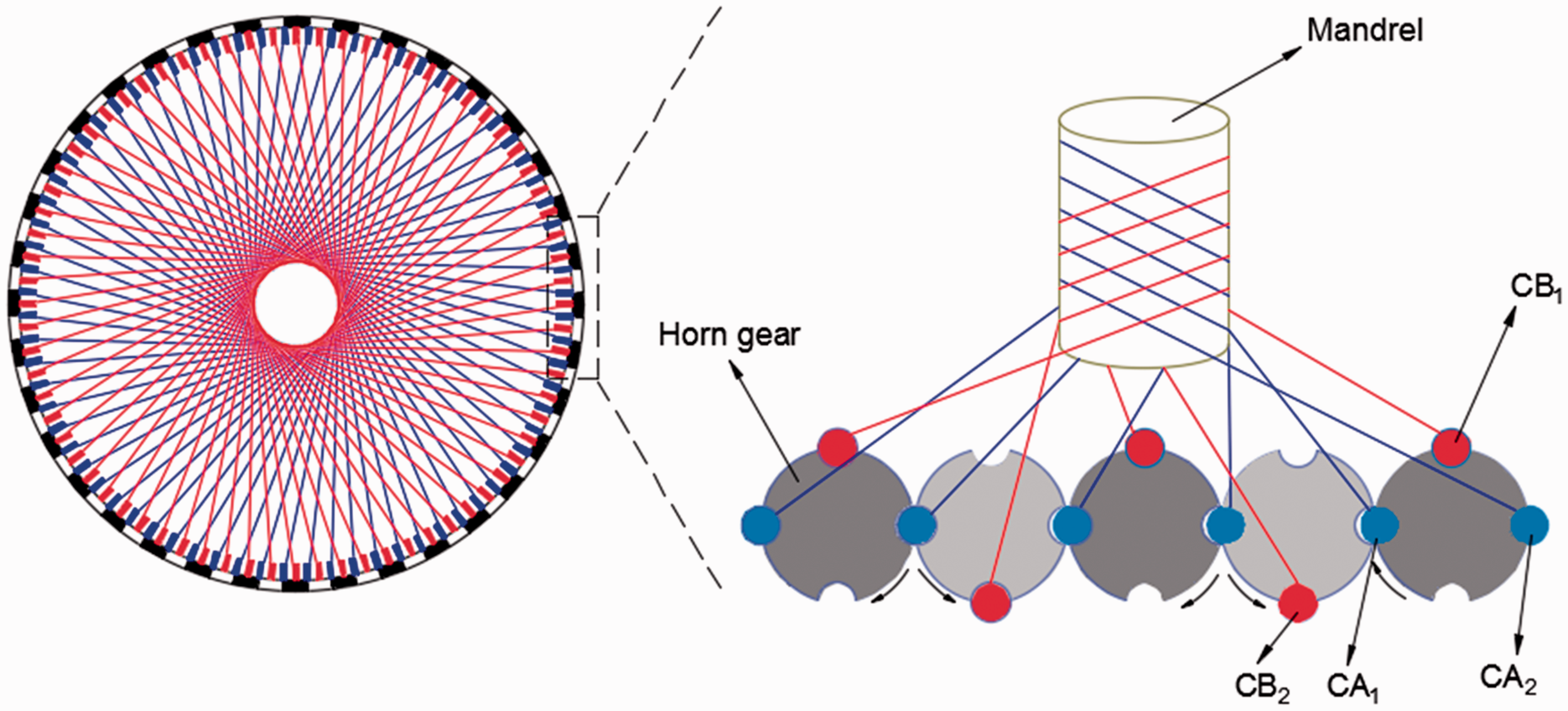
To obtain a better understanding of braiding process, schematic diagram of radial braiding machine with industrial robot is shown in Figure 1. And the radial braiding machine has 88 horn gears, each of which has four slots. The carriers are installed as 1F1E method (a gap is set between two adjacent carriers in the same group); 176 carriers are driven during braiding process. One half carriers move clockwise, while the other half carriers move counterclockwise in the braiding process. As shown in Figure 2, the carriers in CA group move counterclockwise, and the carriers in CB group move clockwise. Meanwhile, the traction system drags robot with the mandrel to move, which can make the mandrel move along the braiding center. In order to obtain the desired fabric, three-dimensional mandrel must be perpendicular to braided surface when it is through the center of the braided ring in the braiding process. As shown in Figure 1, three-dimensional mandrel will be shifted due to the disturbance of yarn tension.
The diagram of mandrel dragged by the robot in three-dimensional braiding machine. The diagram of braiding process.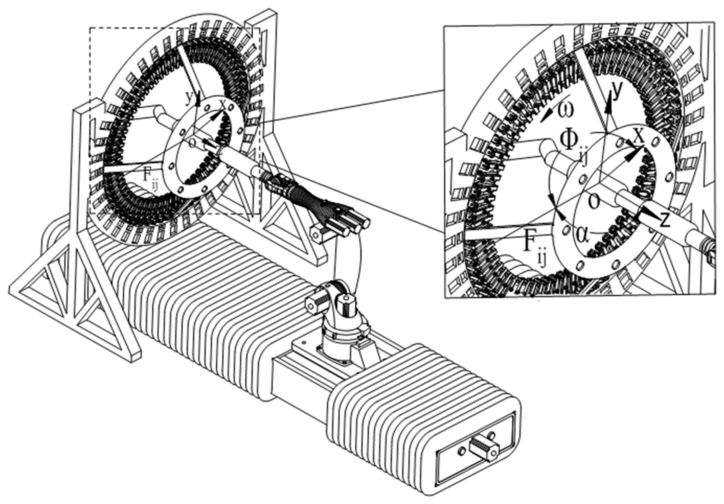
The radial braiding machine has 1 layer and 176 spindles, which is established in the coordinate system as shown in Figure 1. Where, the rotation center of the end effector of robot is the original point, and the direction of X, Y, Z is shown in Figure 1.
Firstly, equations (1) to (3) can be obtained by the decomposition of forces


Three-dimensional mandrel will be shifted by yarn tension including positive braiding yarn, reverse braiding yarn and axial yarn in the braiding process. Then, the force of all yarns on three-dimensional mandrel is shown in equations (4) to (6).

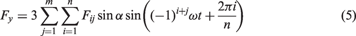

According to equations (4) to (6), the forces of all yarns on three-dimensional mandrel at the direction of X, Y are shown in Figures 3 and 4. And the force of all yarns on three-dimensional mandrel at the direction of Z according to the equation (6) is The diagram of X-axis force of the mandrel in single layer braiding machine. The diagram of Y-axis force of the mandrel in single layer braiding machine.

The simulation process of three-dimensional mandrel offset
In the braiding process, three-dimensional mandrel will be offset due to the effect of yarn tension, which leads to the error of braiding angle. The mechanical module of finite element software is used to simulate the offset of three-dimensional mandrel caused by yarn tension. The equivalent offset of three-dimensional mandrel and offset in the direction of X, Y, Z are obtained by finite element software. Meanwhile, considering the feasibility of calculation and the consistent trend of three-dimensional mandrel within shorter distance of the axis, the following strategy is adopted, that is to analyze the offset of three-dimensional mandrel every 25 mm along the axis.
Boundary condition setting of finite element analysis
In this paper, three-dimensional exhaust pipe is used as braided mandrel. Three-dimensional mandrel diameter of fine end is 80 mm, and the diameter of thick end is 120 mm. The three-dimensional geometric model of exhaust pipe is established by using the mechanical model module of finite element software Workbench 13.0.
In the simulation process, KUKA manipulator has adopted Q345 as material and three-dimensional exhaust pipe has adopted polyoxymethylene (POM) as material.
Constraint setting
Here, the bottom hole of KUKA manipulator is used as a constraint to restrain the six degrees of freedom of X, Y, Z of the fixing screw hole around the bottom, which is shown in Figure 5.
The diagram of the robotic bottom constraint.
Meshing
Because stiffness transfer matrix is needed in finite element calculation, meshing of the model is necessary. Here, grid size of 20 mm is used for the manipulator. Due to the influence of computing speed and grid size on the result, the grid size of three-dimensional exhaust pipe is set to 10 mm. After dividing the grid, the total number of generating units is 219,468 and the number of nodes is 340,338, which is shown in Figures 6 and 7.
The diagram of the overall mesh of robot arm and its mandrel. The diagram of mandrel meshing.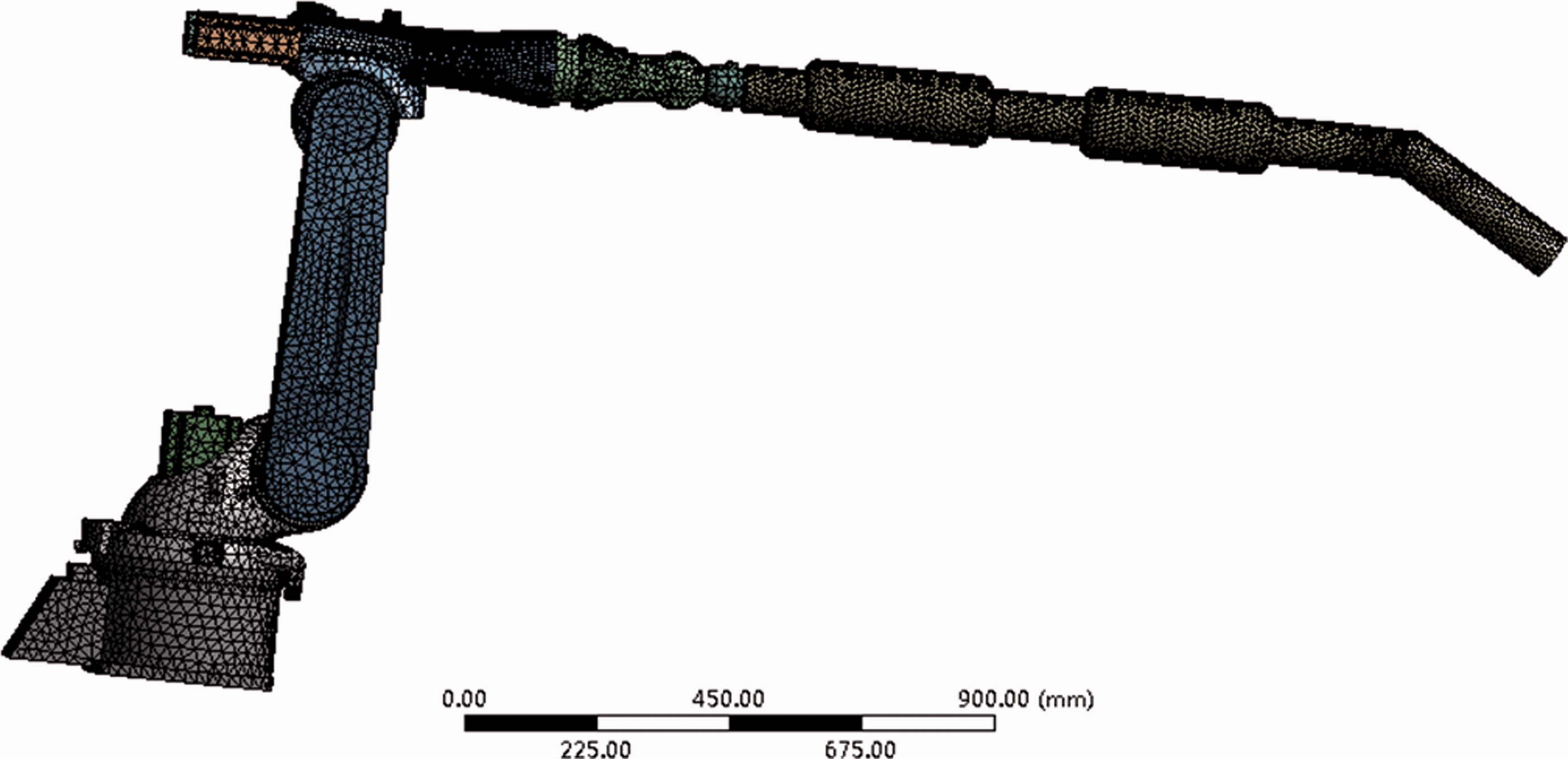

Loading
The loading forces acting on three-dimensional mandrel are shown in formulas (4) to (6). In the braiding process, the force of all yarns acted on the surface of mandrel. In order to make the simulation results consistent with the actual situation, circular curve of loading is drawn along the circumference surface of three-dimensional mandrel, and the loading force acts on the circular curve. The loading force is loaded in the form of components of X, Y, Z, which is shown in Figure 8.
The diagram of the load imposed on mandrel in the braiding process.
Analysis results
The offset of three-dimensional exhaust pipe is analyzed at every 25 mm along the axis direction with consideration of stress-deformation of three-dimensional mandrel in braiding process and the influence of the overall stiffness of three-dimensional mandrel on the offset. The offset of three-dimensional exhaust pipe at 1349 mm is shown in Figure 9 and the actual offset data of X, Y, Z, which is in single layer braiding machine are shown in Figure 10. Table 1 shows the test and estimated offset data of X, Y, Z, which is in single layer braiding machine.
The cloud of mandrel subject to yarn tension. The X-axis, Y-axis, Z-axis offset of mandrel under yarn tension in single layer braiding machine. The estimated offset value and its average relative error in single layer braiding machine.


From Figure 10, offset means X-axis, Y-axis, Z-axis offset of mandrel under yarn tension, Dfx means X-axis offset of mandrel under yarn tension, Dfy means Y-axis offset of mandrel under yarn tension, Dfz means Z-axis offset of mandrel under yarn tension, and the horizontal ordinate in Figure 10 means braiding position.
Based on the above analysis results, it can be seen that the offset of three-dimensional mandrel near the end of the robot is smaller when the loading force along X, Y is small, and the offset of three-dimensional mandrel far away from the end of the robot will gradually increase, which have a great influence on braiding angle. Even smaller loading force will greatly change the braiding angle of three-dimensional mandrel far away from the end of the robot with consideration of longer length and smaller rigidity for some mandrel, which can affect the braiding quality. Therefore, the influence of yarn tension on three-dimensional mandrel must be considered in trajectory planning of robot, and the compensation of robot trajectory based on the above offset data is of great significance to the improvement of braiding quality.
Prediction of three-dimensional mandrel offset based on neural network
In order to get an accurate robot trajectory, it is necessary to know the offset at each moment when three-dimensional mandrel is subjected to yarn tension in the braiding process. The workload that the offset of three-dimensional mandrel at each moment is analyzed by using the finite element software is particularly large. The method is of large computation and time consuming when complex mandrel is analyzed, so that back propagation neural network algorithm is to predict the offset of three-dimensional mandrel at each moment.
The nonlinear relationship between braiding point position and its force of three-dimensional mandrel and the offset of three-dimensional mandrel can be studied due to the highly nonlinear feature of BP neural network.
Parameter setting of BP neural network
Selection of training sample
Seventy-three sets of data are calculated by using the finite element software as the training data of neural network to estimate the offset of three-dimensional mandrel in the other braiding position. The 73 sets of data are analyzed at every 25 mm along the axis of three-dimensional mandrel.
Parameter setting of BP neural network
Due to the influence of braiding point position and force on the offset of three-dimensional mandrel, so braiding point position P, the force of X direction in the braiding point 
According to the above analysis, the topological structure of the neural network is shown in Figure 11.
The topological structure of the neural network.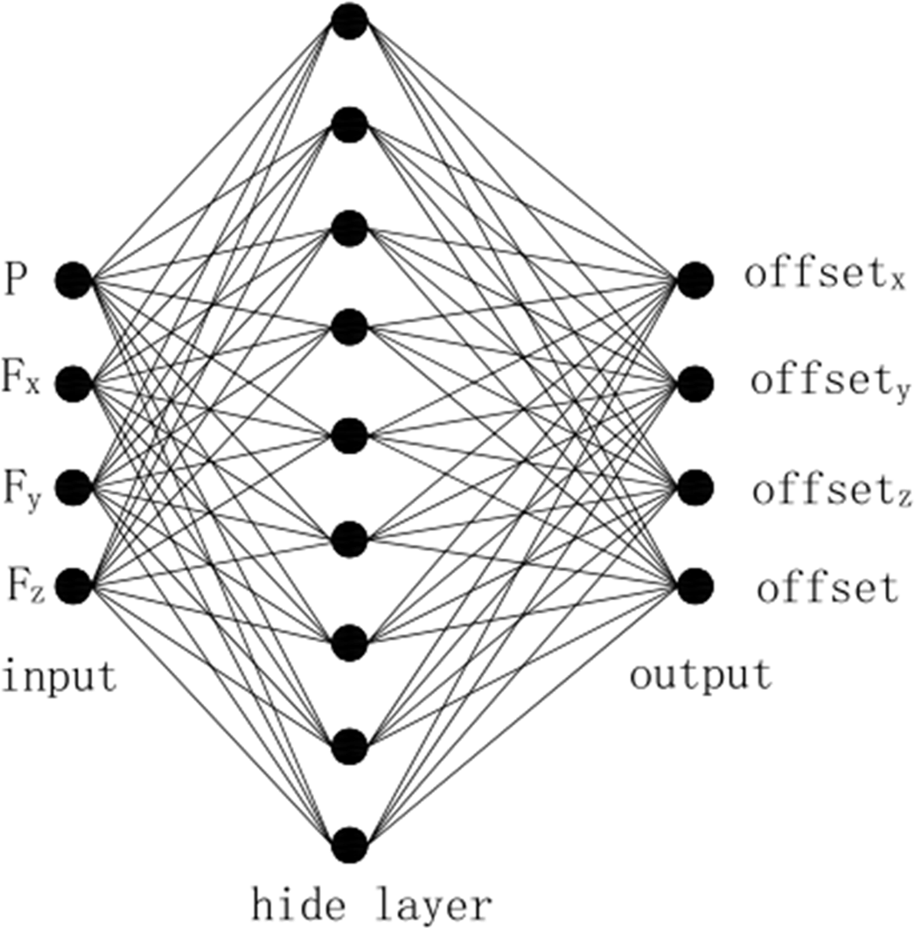
Prediction results and analysis
The offset of three-dimensional mandrel at some moment predicted by BP neural network is shown in Table 1. After the analysis of prediction results, the average relative error between the predicted offset of three-dimensional mandrel and the real value obtained by finite element software is low as shown in Table 1. The prediction results show that artificial intelligence method, such as BP neural network algorithm, is applied to predict the offset of three-dimensional mandrel at each moment, which greatly reduces the computation and improves the efficiency.
The trajectory generation of three-dimensional mandrel based on offset compensation
In order to get the ideal fabric, three-dimensional mandrel must be perpendicular to the braiding surface through the center of the braiding ring. Three-dimensional mandrel is offset due to the effect of yarn tension, resulting in the error of braiding angle. Therefore, in order to obtain an accurate trajectory, the offset of three-dimensional mandrel that is predicted must be compensated at each moment.
Taking three-dimensional exhaust pipe as an example, the schematic diagram of the movement process of mandrel is shown in Figure 12 and the coordinate system is established as shown in Figure 13. The coordinate system takes the center of braiding ring as the origin O1, the normal direction of braiding ring as z direction, the vertical ground plane as x direction, and finally y direction according to the right-hand rule. In the same way O2, O3, O4 coordinates are established, where O1 is the base coordinate system, O4 is the tool coordinate system. It is assumed that the real-time offsets of the three-dimensional exhaust pipe are The schematic diagram of the movement process of mandrel. The diagram of the coordinate system. The structure parameters of mandrel.


The partial coordinates of robot program.

Formula (8) can be obtained by step1 as shown in Figure 12

In the process of braiding from O1 to O2, n track points after offset compensation are easily obtained by formula (8).
When braiding at O2, the robot arm needs to be adjusted its posture so that three-dimensional mandrel rotates clockwise about
Formula (9) can be obtained by step2 as shown in Figure 12.

When the manipulator is adjusted to make O2O3 section perpendicular to the braiding ring, O2O3 braiding section is divided into n track points, and then braiding from O2 to O3
Formula (10) can be obtained by step3 as shown in Figure 12

In the process of braiding from O2 to O3, n track points after offset compensation are easily obtained by formula (10).
When braiding at O3, the robot arm needs to be adjusted its posture so that the three-dimensional mandrel rotates clockwise about
Formula (11) can be obtained by step4 as shown in Figure 12

When the manipulator is adjusted to make O3O4 section perpendicular to the braiding ring, O3O4 braiding section is divided into n track points, and then braiding from O3 to O4.
Formula (12) can be obtained by step5 as shown in Figure 12

In the process of braiding from O3 to O4, n track points after offset compensation are easily obtained by formula (12).
The position and posture of the end of the robot can be calculated through
Experiment
In order to verify the accuracy of trajectory after offset compensation, taking three-dimensional exhaust pipe as an example, a radial braiding machine was used to braid three-dimensional mandrel. The experimental conditions are provided by Xuzhou Henghui Braiding Machine Co., Ltd. The experimental equipment includes a six degree of freedom manipulator, three-dimensional exhaust pipe and the radial braiding machine. The radial braiding machine here consists of 88 dials, 176 spindles, 88 axial yarns, 176 braided yarns, 4 servo motors, 2 vibrator motors, rack, braided chassis, gear transmission system, etc. The three-dimensional mandrel diameter of fine end is 80 mm, the diameter of thick end is 120 mm, yarn width is 3 mm, the diameter of braided ring is 300 mm, the frequency of vibrator motor is 30 Hz and the speed of servo motor is 600 r/min. The control of main motor is programmed via TWINCAT software. The take-up speed of robot is constantly changing here. Taking the braiding position 0 mm–1500 mm of mandrel as an example, the trajectory of three-dimensional exhaust pipe after the offset compensation is generated according to the above method and then the trajectory points are connected by the robot's programming instruction. The braiding process and partial fabric are, respectively, shown in Figures 14 and 15. The partial mandrel with protractor is, respectively, shown in Figures 16 and 17. Finally, braiding angle in the position of 0 mm–1500 mm is obtained by protractor and the comparison of braiding angle is shown in Figure 18.
The physical diagram of braiding process. The physical diagram of partial mandrel. The partial mandrel with protractor in the position of 550 mm–950 mm. The partial mandrel with protractor in the position of 0 mm–550 mm. The comparison of theoretical braiding angle, braiding angle before and after compensation.


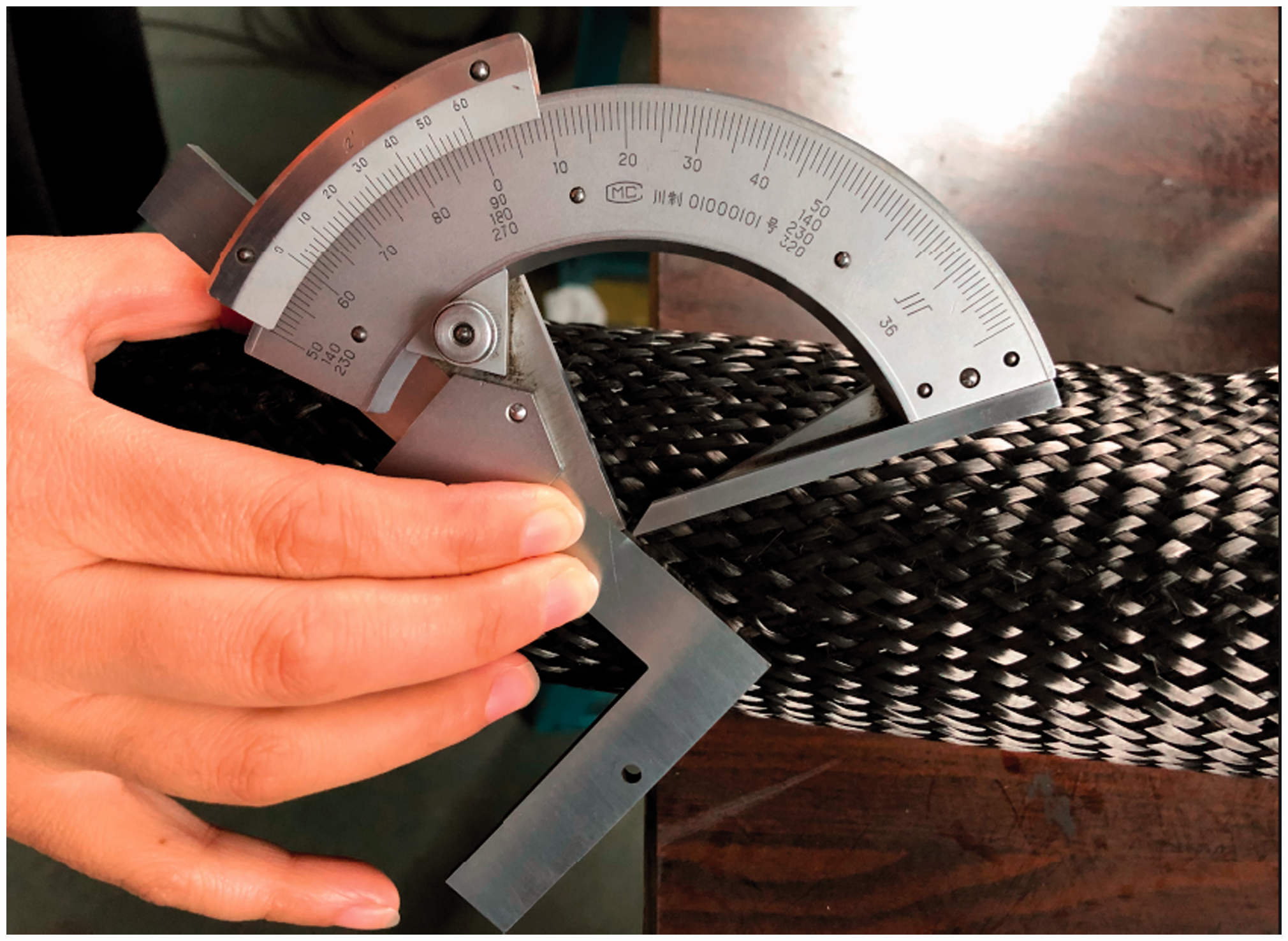

The braiding angle of three-dimensional exhaust pipe was measured by protractor, which is shown in Figures 16 and 17. It can be seen that the theoretical braiding angle of fabric in the position of 0 mm–550 mm, 950 mm–1100 mm, 1400 mm–1500 mm is 30° and the position of 550 mm–950 mm, 1100 mm–1400 mm is 45° as shown in Figure 18. From Figure 18, the trend of braiding angle of the fabric that can be braided through the trajectory of the robot before and after compensation is similar to the theoretical braiding angle. The error of braiding angle of the fabric that can be braided through the trajectory of the robot before compensation in the position of 0 mm–550 mm is large. Firstly, braiding angle has a period of instability in the position of 0 mm–100 mm because the acceleration process is not instantaneous. Secondly, there are fluctuations in the position of 100 mm–550 mm because the speed of robot is small in the arc motion. And the actual braiding angle obviously lags behind the theoretical braiding angle in the position of 550 mm–1500 mm because of the change in the cross-section of mandrel, which will lead to the change of take-up speed because the acceleration process of take-up speed is not instantaneous. Generally speaking, the maximum error of braiding angle of three-dimensional exhaust pipe that can be braided through the trajectory of the robot before the offset compensation is 3.986° with the consideration of the stability period, while the maximum error of braiding angle of the fabric that can be braided through the trajectory of the robot after the offset compensation is 0.8°. Only the stability period is considered here, that is in the position of 100 mm–550 mm, 685 mm–950 mm, 1050 mm–1100 mm, 1240 mm–1400 mm because the acceleration process is inevitable. The error of braiding angle of the fabric that can be braided through the trajectory of the robot after offset compensation is reduced within ±1°, which is in accordance with requirements of braiding. The maximum absolute error of braiding angle of the fabric that can be braided through the trajectory of the robot before and after the offset compensation has reduced to 3.186° in the braiding process. In summary, three-dimensional mandrel will be offset due to the disturbance of yarn tension in the braiding process, which eventually leads to the error of braiding angle. The offset of the three-dimensional mandrel at each moment is obtained by using the neural network to learn the 73 sets of offset data analyzed by the Mechanical module of finite element software. Finally, the research shows the maximum absolute error of the braiding angle of three-dimensional exhaust pipe that can be braided through the trajectory of the robot after the offset compensation is reduced to less than 0.8° in the braiding process, which can meet the braiding requirements. Meanwhile, the larger offset of the mandrel at the bend and the larger offset of three-dimensional mandrel far away from the end of the robot in the braiding process, will result in the larger error of the braiding angle. Thus, the offset compensation for mandrel is very important for braiding high quality fabrics.
Conclusions
In this paper, a precise trajectory generation method of braiding robot with the disturbance of yarn tension was presented. The well-known radial braiding machine with one layer was used to investigate the accuracy of the trajectory generation method with the disturbance of yarn tension. The results show that the trajectory generation method after offset compensation was in accordance with practical engineering.
In conclusion, the trajectory generation method with the disturbance of yarn tension is helpful for engineers in effectively predicting the trajectory of arbitrary shape mandrel in a radial braiding machine. The influence of yarn tension on three-dimensional mandrel is very large. Therefore, the disturbance of yarn tension cannot be neglected when the precise trajectory is studied. This paper provides a prediction way to get the offset of complex mandrel under the disturbance of yarn tension in real time, and the precise trajectory is generated after offset compensation. The error of braiding angle of fabric that can be braided through the trajectory of the robot after offset compensation is reduced within ±0.8°, which lays the technique foundation for creating products with superior mechanical properties. The next area of research could be to study the micro-structure of three-dimensional exhaust pipe and the mechanical relationship between yarns.
Footnotes
Declaration of conflicting interests
The author(s) declared no potential conflicts of interest with respect to the research, authorship and/or publication of this article.
Funding
The author(s) disclosed receipt of the following financial support for the research, authorship, and/or publication of this article: This work was supported by the Program of Jiangsu Innovative Talent (grant number 20171122), the Fundamental Research Funds for the Central Universities and Graduate Student Innovation Fund of Donghua University (grant number CUSF-DH-D-2019097).