
Abstract
In this study, the three-dimensional finite element models of carbon fiber needled felt reinforced composites were built by using the embedded element technique and the virtual yarn method. Three sizes of samples for carbon fiber needled felt reinforced composites were designed and prepared. The tensile properties were investigated by experiments and theoretical methods, and the influences of sample size on tensile modulus were discussed. The results showed that, the longitudinal tensile moduli of carbon fiber needled felt reinforced composites decreased with the increase of sample size. Compared with the rule of mixtures and the inclusion theory, the longitudinal tensile moduli obtained by finite element method were closer to the experimental values. In addition, the transverse tensile moduli obtained by finite element method were greater than that obtained by the rule of mixtures and the inclusion theory. That was due to the orientation of some fibers had a proportion along the thickness. It was concluded that, these three-dimensional finite element models can be used to investigate the elastic properties of carbon fiber needled felt reinforced composites with different sizes.
Introduction
There are two types of fiber-reinforced composites: continuous fiber-reinforced composites and discontinuous fiber-reinforced composites. Discontinuous fiber-reinforced composites are also called short fiber-reinforced composites [1], and they have advantages of simple processing technology, high automation, and lower costs than the continuous fiber-reinforced composites [2]. Besides some nanoscale fiber-reinforced composites [3-5], many large-aspect ratio short fiber-reinforced composites have been widely used, such as sheet molding compounds (SMC) [1], long fiber-reinforced thermoplastics (LFT) [6], glass mat reinforce thermoplastic (GMT) [7], short basalt fiber-reinforced composites (BFC) [8,9], carbon fiber needled felt reinforced composites (three-dimensional (3D) needle-punched C/C composites, such as aircraft brake) [2] etc.
As reviewed in the previous literatures, current theoretical analysis methods to the study of short fiber-reinforced composites can be classified into three types. The first method is the rule of mixtures [10,11], which is more suitable for in-plane isotropic material. In order to simplify calculating, the short carbon fiber layer in composites is considered as an isotropic material by many researchers [12,13]. Nevertheless, if the fiber orientation is taken into account, the accuracy of the prediction results needs further validation [14]. The second method is the inclusion theory [15–17], which is developed based on Eshelby's strain concentration tensor. Fibers are modeled as second phase inclusions in matrix. With an orientation averaging process, this method can also be extended to the prediction of properties in random fiber composites. However, the inclusion theory assumes that the matrix is infinitely large [14]. From our previous study, the longest fiber in our preform is 60 mm, and it is close to the dimension of some composite products (such as vehicle brake) [18,19]. Due to the overlength of the fibers, further verification is required for the application of this assumption, too. The third method is finite element method. The FEM is an effective numerical analysis method, and it has actually obtained many applications.
Many information about composites are required for FEM [20,21]. Besides reliable material properties investigated by many researchers [22,23], the realistic geometry model of composites influenced the credibility of FEM. Many properties predicted by FEM are obtained based on the microstructure representative volume element (RVE) [24]. However, because of the random distribution of fibers, the carbon fiber needled felt reinforced composite is not a periodic-structure material. Hence, it is difficult to calculate in-plane elastic properties based on the RVE. In carbon fiber needled felt reinforced composite, the fiber length fluctuates greatly, and the morphology of each fiber is different. In addition, the location and orientation of fibers are random. As a result, the complexity of such structure makes it very difficult to build the 3D geometry model for these composites. To address these issues, the 3D geometry model of the reinforcement has been built and studied by our previous work [19]. But it is still hard to accurately build the finite elemental model for the composites. In the finite elemental model of carbon fiber needled felt reinforced composites, the smallest unit is single fiber, rather than yarn. Considering the difficulty of meshing for single fiber, some researchers have proposed the embedded element technique, which eliminates the need for a complex meshing algorithm and thus save time in mesh generation [25–27]. Besides, the huge number of fibers also results the long computational time. Although some studies try to change the diameter of fiber, these lack theoretical and experimental basis [28,29]. Therefore, simplifying the finite element model for carbon fiber needled felt reinforced composites is needed.
Moreover, it is found that the model size has a significantly effect on fiber length distribution or average fiber length by our earlier work [19], which may influence the in-plane mechanical property of composites. However, the effects of sample size on elastic modulus have not been studied for carbon fiber needled felt reinforced composites.
To solve the above problems, the 3D finite element models of carbon fiber needled felt reinforced composites were built in this study. The embedded element technique was used to lower the difficulty of meshing, and the virtual yarn method was proposed to reduce the mesh number for reinforcement. Three sizes of carbon fiber needled felt reinforced composites were designed and prepared. The tensile properties of carbon fiber needled felt reinforced composites were investigated by experiments and theoretical prediction, and the influences of sample size on tensile moduli were discussed.
Experiments and methods
Materials
The parameters of raw materials.

Tensile modulus tests
In the present test standards for tensile properties, the size of the composites was specified. To investigate the effects of sample size on tensile properties, the composites had to be cut into pieces of different sizes. According to the engineering mechanics [33], for the sample with rectangular cross section, the ratio of the gauge length l
g
and the cross-sectional area A is specified as

The dimensions of samples can be calculated from equation (1). Based on this, the composite was cut into three kind of samples, and the details were listed in Table 2. These samples were named as S72, S108, and S144, respectively. “S” is the abbreviation of “Sample,” and the number represents the length of the samples. The tensile tests were carried out on AG-250KNE material testing machine (Shimadzu Corporation, Kyoto, Japan). During the tests, full-field strain and displacement fields were obtained with the use of stereovision in conjunction with 3D digital image correlation (DIC) technique on ARAMIS-5M (GOM, Braunschweig, Germany). Furthermore, the tensile modulus could be obtained by using DIC. The tensile testing apparatus were shown in Figure 1.
The tensile testing apparatus in this study. The parameters of the samples.

Embedded element technique
In our finite element model, the matrix material was modeled using a regular array of 8 nodes 3D hexahedral solid element (ABAQUS Type C3D8R), and the fibers were treated as two nodes 3D truss elements (ABAQUS Type T3D2). Truss element was fixed to the solid element using the embedded element technique, a type of multipoint constraint within ABAQUS/Standard. The translational degrees of freedom of each truss element were eliminated when it was embedded, becoming constrained to the interpolated values of the corresponding degrees of freedom of the host (matrix) element. The total stiffness matrix of embedded element 
Virtual yarn method
The total length of carbon fibers in composite could be calculated from the fiber volume fraction easily. For S72, S108, and S144, the total length of carbon fibers was 3.60 × 106 mm, 8.09 × 106 mm, and 1.20 × 107 mm, respectively. Considering the aspect ratio of carbon fiber in reinforcement, there were too much fibers and truss elements to build the finite element model. To solve this problem, the virtual yarn method had been proposed to reduce the mesh number for reinforcement. First of all, we assumed that the composite was composed of many virtual yarns. It could be seen in Figure 2, the truss element in the finite element model of composites was treated as virtual yarn, which was composed of matrix and carbon fibers. In virtual yarn, the fibers are parallel to each other, and the axial direction of all the fiber is along the virtual yarn length. It is interesting that the fiber bundles (like the virtual yarn we proposed) can be seen in real composites [1,18].
The schematic of virtual yarn method.
As we know, the less the fibers in each virtual yarn, the more truss elements in finite elemental model, which requires greater computation. In this study, we assumed the fiber number in each virtual yarn was 1000. The radius of truss elements was assigned as a function of number of fibers and fiber volume fraction of virtual yarn (90% in this study). Based on this, the engineering constants of virtual yarn could be calculated by using a simple the rule of mixtures, and the equations were listed as follows.

The engineering constants of virtual yarn.

Results and discussions
3D finite element model
In our previous works, the fiber-shift method is presented to generate the 3D geometric model of reinforcement, and curved carbon fiber is regarded as beam under pure bending [19]. The finite mixture model is applied to describe the fiber length distribution. Closed model, open model, and cut model have been proposed, and cut model is thought to be closer to reality. The orientation, length, and geometric location of carbon fibers were calculated based on the statistics of carbon fiber felt specimens. On the basis of these studies, a 3D geometry model for carbon fiber needled felt reinforced composites can be built by using Python script and ABAQUS. As described in Virtual yarn method section, the virtual yarn was used to reduce the mesh number for reinforcement, which was composed of resin and 1000 fibers. Based on number of fibers and fiber volume fraction of virtual yarn, the radius of virtual yarn was 1.17 × 10⁻¹ mm. The total length of virtual yarn of geometry model could be obtained during the generation of virtual yarn, and the total length would determine the fiber volume fraction of final finite elemental model.
The generation process for final 3D geometry model used in FEM lists as follows:
Generate a big 3D geometry model, and the dimension was 324 × 324 × 6 mm3. The big 3D geometry model would be cut into three small cut models with different sizes in ABAQUS. Obtained by using Python script, the average fiber length of the small model of S72, S108, and S144 was 11.22 mm, 14.15 mm, and 16.64 mm, respectively. These cut small models were compressed to be dense and thin. Concerning the interactions between fibers, the carbon fibers were treated as beam elements. After that, the fiber volume fraction of compressed model was equal to the experimental value. The modeling process was illustrated in Figure 3. The illustration of modeling process of final 3D geometry model for reinforcements: (a) S72; (b) S108; and (c) S144.

Based on the final 3D geometry model for reinforcement, the finite elemental models could be built. Before that, the embedded element technique was used to fix the fiber elements to matrix elements. In fiber reinforced composites, the resin is distributed among fibers. As a result, the interaction between fibers could be ignored in finite elemental model during the elastic deformation stage of the composites. So that the truss element in the finite element model was treated as virtual yarn. Based on these, the 3D finite element models were built, which could be used to predict the elastic modulus of carbon fiber needled felt reinforced composites.
Experimental results
The failed samples of S72, S108, and S144 obtained from experiments as shown in Figure 4(a). Different from 3D braided or other laminated [35] composites, the carbon fibers in carbon fiber needled felt reinforced composites were scattered and not in form of fiber bundles. The distribution of fibers is more evenly in resin than that of yarns, which resulted that there was few resin-rich area in carbon fiber needled felt reinforced composites. When the samples were subjected to tensile stress, each carbon fiber was loaded independently, which could distribute the tensile stress more evenly in cross-section. Therefore, the fractures of the failed samples were relatively smooth (Figure 4(b)). Compared with 3D braided composites (Figure 4(c)), the failure mechanism of carbon fiber needled felt reinforced composites was mainly reflected in the pullout, interfacial debonding, and fracture of single fiber, without the fracture of fiber bundle. In Figure 4(d), there were a lot of broken carbon fibers distributed randomly in the fracture region.
Tensile fracture morphology of failed samples: (a) failed samples of carbon fiber needled felt reinforced composites; (b) fracture surfaces of S144; (c) fracture surfaces of 3D braided composite; (d) enlargement of fracture surfaces of S144.
The major strain distribution (colored nephogram) and direction of maximum strain (marked by black arrow) of carbon fiber needled felt reinforced composites obtained by DIC were illustrated in Figure 5. It was noted that, the distributions and changes of the maximal strain direction of different sizes were consistent with each other. During the initiation of loading (Stage 1), the direction of maximum strain was randomly distributed, which was caused by the random orientations of carbon fibers. It was shown that composites generate elastic deformation at this stage. Along with the increasing of the load, the deformation of the composites was beyond elastic range, the direction of the maximum strain was gradually shifted to the loading direction (Stage 2). At this moment, the matrix cracking, interfacial debonding, and fiber fracture might occur in composites. These damages continued to accumulate until samples failed. Before that, the strain concentration could be seen at the location of fracture on the surface of samples (marked by red rectangles in Stage 3). The longitudinal tensile strengths and moduli were listed in Table 4, and the results were the average of five test samples. It was noted that the tensile strengths of different sizes were close. Above all, the effects of sample size on the major strain distribution, the fracture morphology and the tensile strength of different sizes were not distinct.
The major strain distribution and direction of maximum strain obtained by DIC: (a) S72; (b) S108; and (c) S144. The tensile properties obtained by experiments.

It was interesting that the longitudinal tensile modulus decreased with the increase of sample size. As we mentioned in 3D finite element model section, the length distribution of carbon fibers in carbon fiber needled felt reinforced composites was influenced by the sample size, so the longitudinal tensile moduli of composites with different sizes should be different. Considering that the strains were mainly concentrated in the region between two tabs, L was defined as the length factor in this study, which was the ratio of average fiber length to the distance of two tabs for composites

Prediction results of tensile modulus
For the oriented aligned short fiber-reinforced composites, the elastic modulus could be calculated by the rule of mixtures [11,12]

Based on the equations above, the tensile modulus of carbon fiber needled felt reinforced composite could be calculated by

Besides, the carbon fiber needled felt reinforced composite could be assumed as the homogeneous isotropic material and the compliance tensor 


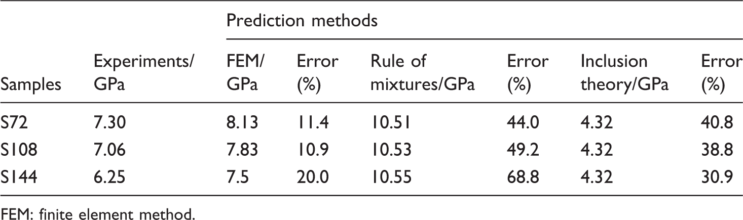
All the measured and the predicted results of longitudinal tensile moduli were described in Table 5 and plotted in Figure 6. It was noted that, the prediction results of the FEM were closer to the experimental values than that of the rule of mixtures and the inclusion theory, which verified the availability of the 3D finite element model of carbon fiber needled felt reinforced composites. Most importantly, the longitudinal tensile moduli obtained by FEM decreased with the increase of sample size, which was in good agreement with the experimental results. By contrast, for the rule of mixtures, the average fiber length increased from 11.22 mm to 16.64 mm (3D finite element model section), but the longitudinal tensile modulus nearly kept constant around 10.57 GPa. These results were close to the stochastically aligned continuous fiber reinforced composite with the same fiber volume fraction (10.63 GPa, E11 in equation (3)). In fact, when the fiber length was more than 1 mm, the effects of fiber length on prediction results were not pronounced. Moreover, by using the inclusion theory, the longitudinal tensile modulus was obtained without considering fiber length. It seemed that these prediction results were not influenced by fiber length at all, and the fiber orientation distribution was ignored, either. However, our previous work shows that the model size has a significant effect on fiber length distribution or average fiber length [19], from which the in-plane mechanical properties of carbon fiber needled felt reinforced composites were determined. As a result, the rule of mixtures and the inclusion theory could not show the influences of reinforcement structure on longitudinal tensile moduli of the composites. In addition, when the dimension of composite was large enough, the carbon fiber needled felt reinforced composites were similar to particles reinforced composite, and there might be a minimum value of the longitudinal tensile modulus. It was thought that the prediction result of the inclusion theory might be considered to be the minimum value of carbon fiber needled felt reinforced composites. Similarly, when the dimension of composite was very small, this composite was similar to continuous fiber reinforced composite. There might be a maximum value of longitudinal tensile modulus, which could be E11 (10.63 GPa) calculated by in equation (3).
The comparison of longitudinal tensile moduli of carbon fiber needled felt reinforced composites. Tensile modulus of three kinds of samples. FEM: finite element method.
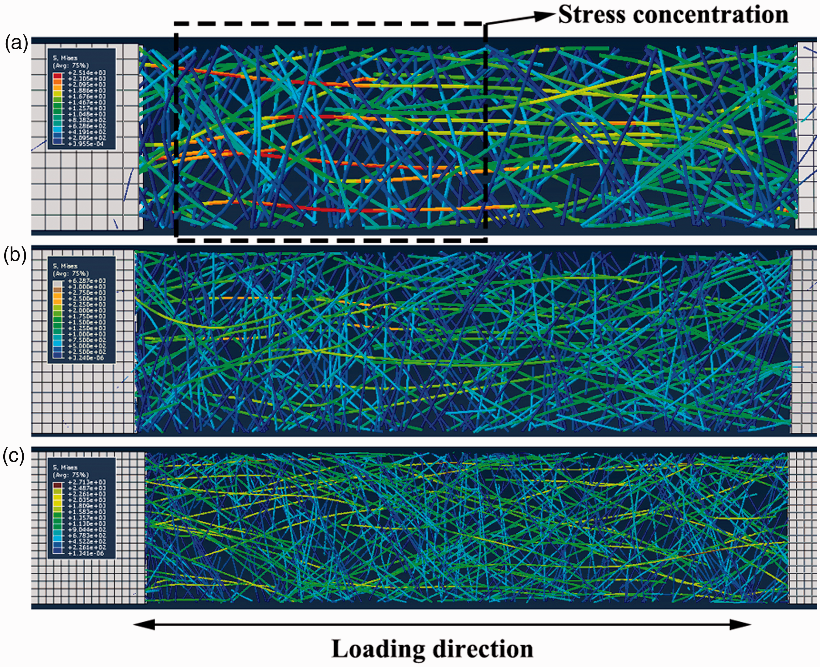
At the stage of elasticity deformation, the major strain distribution and direction of maximum strain of carbon fiber needled felt reinforced composites obtained by DIC and FEM were compared in Figure 7. It was pointed out that the major strains of finite element models were uniformly distributed, and the directions of maximum strain were oriented randomly. The major strain distribution and direction of maximum strain of three finite element models were not influenced by the sample size. These phenomena were similar to the experimental results, which were caused by the randomly distribution of fibers in carbon fiber needled felt reinforced composites. Based on the 3D finite element models, the stress distributions of carbon fibers were obtained and shown in Figure 8, which could be used to study the effects of sample size on the longitudinal tensile modulus. It could be seen that significant stress concentration appeared in carbon fibers oriented along the loading direction. The smaller the angle between the fiber and the loading direction, the more obvious the stress concentration on this fiber. When the composites were subjected to longitudinal tensile stress, these carbon fibers determined the stiffness of composites. The distance of two tabs for S72, S108, and S144 was 42 mm, 64 mm, and 84 mm, respectively, and the longest fiber in these models was 60 mm. As a result, some carbon fibers might be lying from one tab to another in S72. As seen in Figure 8(a), some fibers were oriented along the loading direction throughout the model. They were similar to continuous fibers in composites, which could improve the longitudinal tensile modulus considerably. It was clear that these fibers have higher stress levels (marked by using black dotted line). For S108 and S144, there were no such fibers oriented throughout the model, so the longitudinal tensile moduli were smaller than that of S72. According to the stress transfer theory of short fiber reinforced composites [36], compared with S108 and S144, S72 was closer to the continuous fiber reinforced composites. So that, the longitudinal tensile moduli of carbon fiber needled felt reinforced composites decreased with the increasing of sample size.
The comparison of the major strain distribution and direction of maximum strain between predictions and experiments: (a) S72; (b) S108; and (c) S144. The stress distribution of carbon fibers for FEM when subjected to longitudinal tensile stress: (a) S72; (b) S108; and (c) S144.
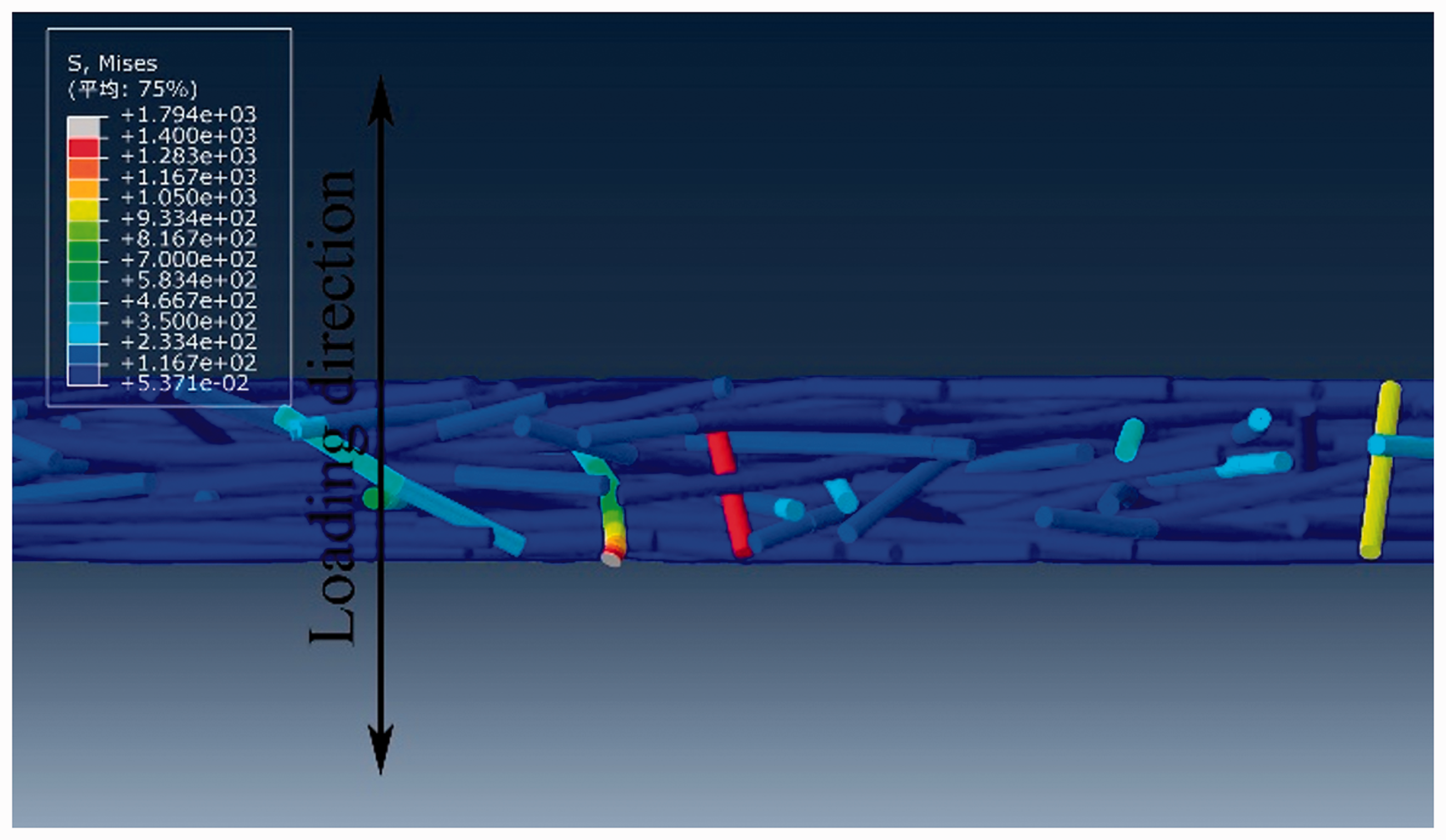
From equation (3) and equations (5)–(8), the transverse tensile modulus of carbon fiber reinforced composites could be predicted by using the rule of mixtures and the inclusion theory, respectively. The validations were carried out by using FEM, which verified on longitudinal tensile modulus, and the results were illustrated in Figure 9. It was noted that, the prediction results were ranged from 4.32 GPa to 5.43 GPa, which was much lower than longitudinal tensile modulus of experiments. For the prediction of the rule of mixtures and the inclusion theory, the transverse tensile modulus was obtained without considering fiber length. For FEM, the randomly distribution of carbon fibers led to the slight variations of prediction results. It was clear that the orientation of some fibers had a proportion along the thickness. These carbon fibers would improve the transverse tensile modulus significantly, and visible stress concentrations were found in Figure 10. That might be the answer to the question that why the transverse tensile moduli obtained by FEM were greater than that obtained by the rule of mixtures and the inclusion theory.
The prediction results of transverse tensile moduli of carbon fiber needled felt reinforced composites. The stress distribution of carbon fibers in carbon fiber needled felt reinforced composites when subjected to transverse tensile stress (S108).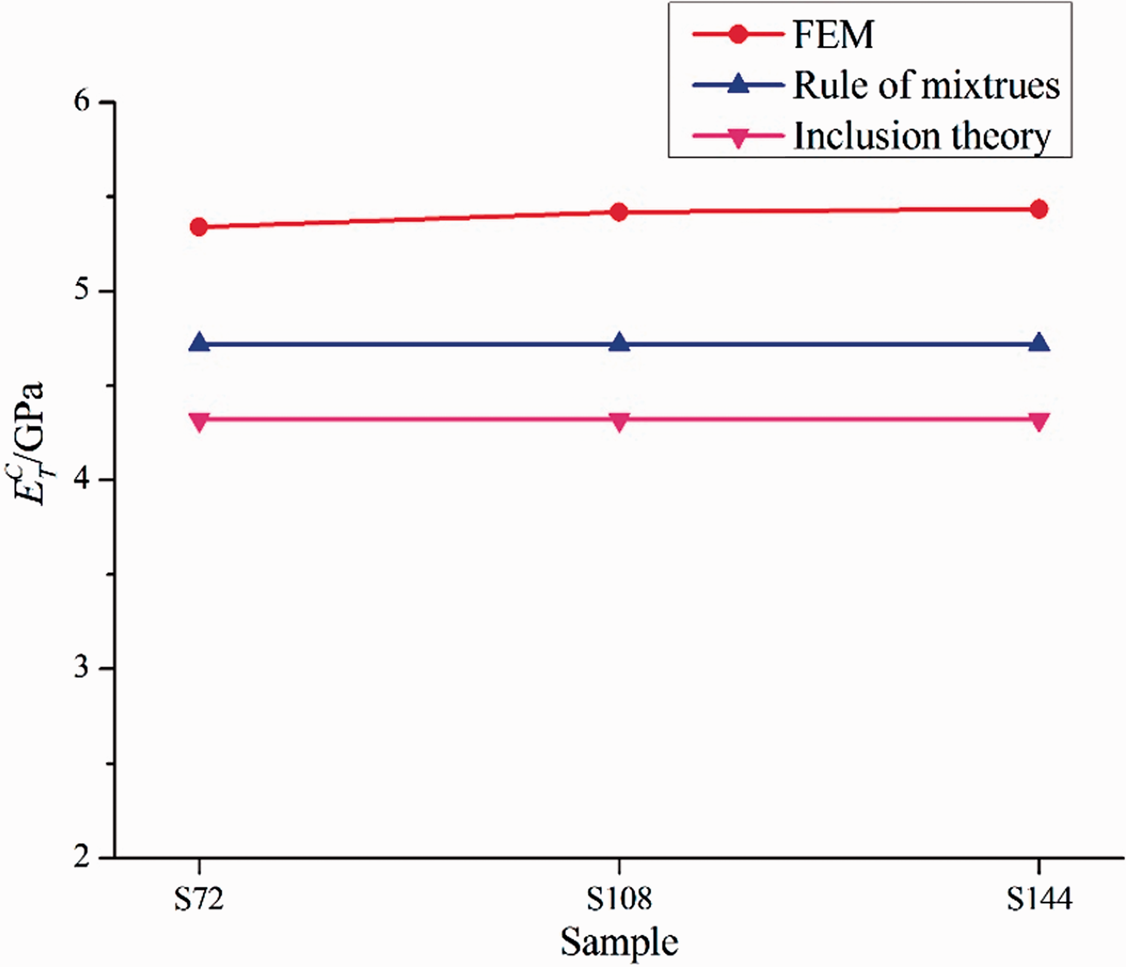
Conclusion
In this study, the embedded element technique was used to lower the difficulty of meshing, and the virtual yarn method was proposed to reduce the number of reinforcement units. On the basis of these, the 3D finite element models of carbon fiber needled felt reinforced composites with different sizes were built.
Three sizes of carbon fiber needled felt reinforced composites were prepared. The tensile modulus was analyzed by experiments and theoretical methods, and the effects of sample size on the tensile properties of the composites were discussed. The experimental results showed that the longitudinal tensile moduli of carbon fiber needled felt reinforced composites decreased with the increase of sample size. Moreover, the prediction results of the FEM were closer to the experiments than that of the rule of mixtures and the inclusion theory. The rule of mixtures and the inclusion theory could not show the influences of reinforcement structure and size on longitudinal tensile moduli of the composites. For carbon fiber needled felt reinforced composites with different sizes, the maximum value of longitudinal tensile modulus could be calculated by the rule of mixtures, and the prediction result of the inclusion theory might be the minimum value. Finally, the transverse tensile moduli of carbon fiber needled felt reinforced composites were predicted by the FEM, the rule of mixtures and the inclusion theory, respectively. It could be seen that the transverse tensile moduli obtained by FEM were greater than that obtained by the rule of mixtures and the inclusion theory. Based on these studies, the more accurate elastic properties of carbon fiber needled felt reinforced composites with different sizes can be obtained. Furthermore, the finite elemental modeling method and the theoretical analysis method can be used to investigate the properties of composites reinforced by large aspect ratio short fibers. That is helpful for the designing and using of short fiber reinforced composites, such as SMC, GMT, LFT, BFC and 3D needle-punched composites. In addition, more investigations can be carried out by using 3D finite element models of carbon fiber needled felt reinforced composites.
Footnotes
Declaration of conflicting interests
The author(s) declared no potential conflicts of interest with respect to the research, authorship, and/or publication of this article.
Funding
The author(s) disclosed receipt of the following financial support for the research, authorship, and/or publication of this article: The authors gratefully acknowledge the financial support from the Key Project of Chinese National Programs (2016YFB0101704), Strategic Priority Research Program of Chinese Academy of Sciences (XDA17020405), Chinese Academy of Sciences and Technology Services Network program, Ningbo International Cooperation Project (2017D10025) and Ningbo Key Industrial Project (2017B10007).