The acoustic performance of fibrous materials is mainly determined by its airflow resistance, and it is a parameter of the resistance that the airflow meets through the materials. This paper has summarized the recent advances on the measurements, calculations and applications of airflow resistance. Firstly, different methods for airflow resistance measurements are presented, mainly including the direct airflow method, alternating airflow method and acoustical method. We have summarized the development history, current status and industrial applications of these methods. Secondly, this paper has summarized the models of calculating airflow resistance. Most of these empirical models are based on the characteristic parameters of fibrous materials, for instance bulk density, fiber diameter, porosity and thickness. Thirdly, this review has gathered the applications of airflow resistance in sound absorption and noise control. It is a crucial parameter in the prediction of both normal incidence sound absorption and reverberation chamber sound absorption. In conclusion, this review has concluded with some perspectives for the measurements, calculations and applications of airflow resistance.
Airflow resistance is a key parameter to evaluate the acoustical properties of fibrous materials, and it is a measure of how easily air can enter into porous absorber [1–4]. It can be defined as the ratio between the pressure drop and the airflow velocity passing through the sample layer. The airflow resistance is analogous to the definition of electrical resistance as the ratio between voltage drop and current. According to ISO 9053 standard, the parameters of airflow effects are classified as airflow resistance, specific airflow resistance and airflow resistivity [5]. These expressions are described as follows
where R is airflow resistance with the unit of Pa s/m3, Rs is specific airflow resistance with the unit of Pa s/m and σ is airflow resistivity with the unit of Pa s/m2. qv denotes the volumetric airflow rate in cubic meters per second (m3/s), A is the cross-sectional area of the test specimen perpendicular to the direction of airflow in square meters and d is the thickness of the test specimen. In addition, the unit of MKS Rayl is equivalent to Pa s/m and 1 CGS Rayl is equivalent to 10 MKS Rayl. Different units concerning airflow resistance, specific airflow resistance and airflow resistivity are listed in Table 1.
Commonly used units of airflow resistance, specific airflow resistance and airflow resistivity.
Parameter
Unit 1 (Rayl)
Unit 2 (Pa)
Unit 3 (kg)
Unit 4 (N)
Airflow resistance R
MKS Rayl/m2
Pa s/m3
kg/s m4
N s/m5
Specific airflow resistance Rs
MKS Rayl
Pa s/m
kg/s m2
N s/m3
Airflow resistivity σ
MKS Rayl/m
Pa s/m2
kg/s m3
N s/m4
However, it should be pointed out that the value of airflow resistance is dependent on frequency for sound absorption applications. According to reported studies, airflow resistance is stable when frequency tends to zero, which is generally called static airflow resistance. It plays a critical role in calculating various acoustic parameters of fibrous materials, such as characteristic impedance, propagation constant and sound absorption coefficient [6]. In 1985, Ingard and Dear [7] have reported an experimental method to test the dynamic airflow resistance through a standing wave tube and two microphones. The dynamic airflow resistance comprises both real and imaginary parts, which is a function of sound wave frequency. Similar to static airflow resistance, dynamic airflow resistance is also a powerful tool to characterize sound absorption properties. As reported by Beranek and Vér [8], airflow resistivity is gradually increased with the increasing of temperature, and the relationship is shown as follows
where σ20 is the airflow resistivity at 20℃, Te is temperature. This effect could be attributed to the dependence of sound velocity and air density on temperature.
Airflow resistance is a basic parameter to describe the intrinsic characteristics of porous media [9–13]. According to reported studies, different fibrous materials with similar airflow resistance but different areal density and fiber diameter might have acoustical properties [14–16]. The sound absorption properties of fibrous materials can be predicted from airflow resistance through modeling approaches, such as the famous Delany-Bazley empirical model and its modifications [17–20]. Airflow resistance is widely used to evaluate the potential acoustical applications of various porous materials, such as sugarcane waste [21], recycling coal bottom ash [22], natural jute fibers [23], indoor plants [24], forest edge [25], periodic groove structure [26], wood-wool cement board [27] and bimodal structured polylactide foams [28]. In this paper, we have mainly reviewed the measurements, calculations and applications of airflow resistance. Section “Measurements of airflow resistance” is mainly focused on the measurement techniques of airflow resistance, including the reported direct airflow method, alternative airflow method and acoustical method. In section “Calculations of airflow resistance”, various models to calculate airflow resistance have been gathered. These models are based on the bulk density, fiber diameter and other micro-structural characteristics of fibrous materials. The applications of airflow resistance are given in section “Applications of airflow resistance”, including the prediction of normal incidence absorption and reverberation absorption. In conclusion section, a summary of airflow resistance is given, and the prospect in this limited area is also pointed out.
Measurements of airflow resistance
The accurate measurement of airflow resistance is important for characterizing the sound wave propagation in fibrous materials. The test methods for airflow resistance are categorized as direct airflow method, alternating airflow method and acoustical method. In this section, the development history and the status of airflow resistance measurements are reviewed as follows.
Direct airflow method
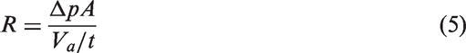
The principle of direct airflow method is defined as the ratio of pressure drop and steady airflow velocity through specimen, and it was firstly reported by Brown and Bolt [29]. To measure airflow resistance, four parameters are needed, including pressure Δp in pascals, cross-sectional area A in square meters, airflow volume Va in cubic meters and time t in seconds are utilized in the calculation of specific airflow resistance. The equation of specific airflow resistance R is shown as follows
The steady airflow is gradually passing through the sample by siphoning water from the tank and tube. The volume of water flowing out from water tank is equivalent to the volume of air through the sample. The pressure drop across the specimen was measured by the manometer connected to the sample holder [30]. Furthermore, a simplified analytical balance method for measuring the airflow resistance was developed by Leonard [31], and the illustration is shown in Figure 1(a). The pressure drop through the test specimen is equivalent to the weight added or deducted from the right-hand pan of the balance, where the balance was divided by the area of the displacement cylinder A. In addition, B is sample holder, C is porous layer and D is the liquid seal for cylinder. Compared with the initial water tank method, analytical balance method is more effective to eliminate the measurement error of extremely low velocity airflow passing through the sample layer.
Diagrammatic sketch of direct methods for measuring airflow resistance: (a) Leonard method [31]; (b) standardized method of ISO 9053 [5]; (c) standardized method of ASTM C522 [32].
According to ISO 9053 standard [5], the diagrammatic sketch concerning the basic test principle of direct airflow method is shown in Figure 1(b). The controlled unidirectional airflow is passing through the circular specimen, and the pressure drop between the two sides of the sample was measured. The equipment system consists of a cell to clamp the specimen, steady airflow source, a device to test volumetric airflow rate, a device to test pressure drop and a scale to measure the thickness of sample. It is suggested that the airflow velocity should be down to 0.5 mm/s, while the precision accuracy of pressure drop device should be as low as 0.1 Pa, thus to improve the reliability of measurements. This direct airflow method was also specified in ASTM C522 standard [32]. The diagram of this method is shown in Figure 1(c). An air supply was taken to force airflow passing through the sample uniformly, and a flowmeter was used to measure the volume velocity of airflow. Pressure drop device was used to test the air pressure difference between the face of sample with respect to standard atmosphere. In addition, this standard was designed for the measurements when specific airflow resistance is ranging from 100 to 10,000 Pa s/m, airflow velocity is ranging from 0.5 to 50 mm/s and pressure drop between the two sides of specimen is ranging from 0.1 to 250 Pa. It is applicable to test the airflow resistance of various acoustical materials including thick blanket, fabrics, papers and screens [33–36]. The round-robin has indicated that the measurement error between different laboratories might be even higher than 30% [37,38]. In addition, it has been reported that airflow resistance could also be deduced from the measured air permeability according to ISO 9237 [39–41]. This method is rather facile because the testing process could be operated by the widely used air permeability equipment. However, the drop pressure specified in ISO 9237 is generally ranging from 50 to 500 Pa, which is higher than the sound drop pressure in standardized test process of ASTM C522 and ISO 9053.
Alternating airflow method
Another method based on alternating airflow has also been standardized by ISO 9053 [5]. Compared with the steady direct airflow method, this approach does not need airflow gauge, and the oscillating piston with known volume velocity could force an alternating airflow through the sample. The schematic diagram of the general principle of alternating airflow method is shown in Figure 2(a). An alternating airflow is slowly passing through the specimen, and the alternating pressure of the volume enclosed by the specimen was measured. The equipment system consists of a cell, an alternating airflow source, a device to test the alternating pressure in the measurement volume and a scale for measuring the thickness of sample [42]. The alternating volumetric airflow is supported by a piston which moves sinusoidally at the frequency of 2 Hz. The effective value of qv with the unit of m3/s could be described as follows
where f is the frequency of piston in hertz, h is the stroke of piston in meter and Ap is the cross-sectional area of piston in square meter. In addition, the linear airflow velocity u and alternating pressure pa are given as follows
where P0 is the atmospheric pressure in pascals, Vp is the product of the amplitude and cross-sectional area of the piston with the unit of cubic meter and Vb is the volume of measurement vessel in cubic meter.
Diagrammatic sketch of alternating airflow methods for measuring airflow resistance: (a) alternating airflow method specified in ISO 9053 [5]; (b) modified alternating airflow method of Norsonic [43].
Based on ISO 9053 standard [5], Norsonic Co. Ltd. has developed a commercial alternative airflow measurement system to characterize airflow resistance. The diagram of airflow resistance test principle is shown in Figure 2(b). An airflow qp is generated by the movement of piston which enters the vessel with volume V, and the airflow passed through the sample is qv. The principle of air pressure p due to the movement of piston is described as follows
where γ is the ratio of specific heat for air and it equals to 1.4, P0 is the standard atmospheric air pressure. In addition, the airflow through the specimen is qv, which is proportional to air pressure p and inversely proportional to airflow resistance R. The generated airflow qp is determined by the area of piston Ap, piston movement frequency f and peak-to-peak amplitude of piston movement h. The equations of qv and qp are as follows
Then airflow resistance R could be obtained by solving the following differential equation
Acoustical method
As reported by Delany and Bazley [17], airflow resistivity is related to characteristic impedance and propagation constant, and these two parameters could be measured by the impedance method [44]. Woodcock and Hodgson [45] have deduced the equations to obtain airflow resistivity according to Delany-Bazley model. The airflow resistivity could be calculated from the real and imaginary part of characteristic impedance and propagation constant. Currently, several acoustical methods have been proposed to measure the airflow resistance of fibrous materials. For instance, Ingard and Dear [7] have developed a system to test the airflow resistance. The equipment consists of a cylindrical tube, a rigid termination, a loudspeaker and a pair of microphones, as shown in Figure 3(a). It is assumed that the thickness of specimen is d, and the distance between the posterior side of the specimen and the rigid termination is l. One microphone is placed at the front side of the sample and another microphone is placed closely to the rigid termination, therefore to measure the sound pressure level Lp1 and Lp2, respectively. The acoustic wavelength λ should satisfy λ ≫ 1.7 D, where D is the inner diameter of the tube. The specific airflow resistance Rs could be calculated by the following equation [46]
where ρ0 is the density of air, and c0 is the velocity of acoustic wave in the tube. Furthermore, with the assistance of dual channel Fast Fourier Transform (FFT) analyzer and broadband stationary random noise source, the specific airflow resistance could be directly calculated by the imaginary part of the transfer function. The equation is expressed as follows
Diagrammatic sketch of acoustical methods for measuring airflow resistance: (a) two microphones method with rigid termination [7]; (b) two microphones method with absorption wedge [48]; (c) three microphones method [49]; (d) two microphones method in accordance with ISO 10534-2 [6].
Therefore, it is applicable to obtain the dynamic airflow resistance, thus to provide enough information to characterize the acoustical behavior. Recently, this method was taken to measure the airflow resistivity of cigarette filter, and the relationship between porosity, bulk density and airflow resistivity was also studied [47].
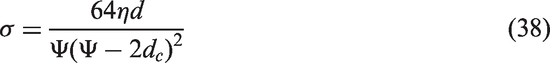
Ren and Jacobsen [48] have proposed a modified two microphones method to test dynamic airflow resistance. Different from the method of Ingard and Dear, the rigid termination was replaced by an absorbing wedge, as shown in Figure 3(b). The sample was located at the middle of impedance tube coordinate, and the locations of two microphones are x1 = L1 and x2 = L2. The airflow resistance is a function of the frequency, and the calculation needs to measure the transfer function between the acoustic signals from two microphones on both sides of the sample. Based on Ren and Jacobsen’s method, Picard and coworkers [50] have developed a technique to measure the dynamic flow resistance and effective static flow resistance of porous materials. The impedance tube is also terminated by an absorption wedge, and the sample is backed with an air gap. The dynamic airflow resistance could be calculated from the real part of dynamic airflow impedance defined by the ratio between complex acoustic pressure and complex airflow velocity through the sample. Furthermore, an acoustical method based on three microphones impedance tube to measure airflow resistance was also developed. The diagram of standing wave tube with three microphones is depicted in Figure 3(c). This configuration allows the simultaneous measurement of sound absorption coefficient, the sound transmission loss and the effective acoustical parameters of the tested porous materials. It has been reported that the airflow resistivity can be determined from the asymptotic behavior of the imaginary part of the dynamic density [51]. The calculation of airflow resistivity σ involves the porosity φ and effective density ρe, which could be described as follows [49]
where ω is angular frequency, d is the sample thickness. The surface impedance Zs, characteristic impedance Zc and wavenumber k could be obtained by the sound wave pressure transfer function measurements. In this method, the open porosity of specimen is prior known, and an impedance tube measurement backed with hard termination and microphone is necessary.
Recently, an acoustical method for measuring the airflow resistance with impedance tube has been established according to the standard of ISO 10534-2 [6]. In this method, the specific acoustic impedance on the front side of specimen is measured by transfer function method. Then the characteristic impedance, propagation constant and airflow resistance are determined. An illustration of measurement system according to ISO 10534-2 is shown in Figure 3(d). It could be observed that two microphones are located at the same side of the specimen, the thickness is 2l, and the air gap distance is La. Zc, k and ZL are the characteristic impedance, complex wave number and the acoustic impedance at the back of the specimen. For a measurement system when L is zero and nonzero, the surface acoustic impedance Zs is denoted as Zs,0 and Zs,L, respectively. The airflow resistance R could be calculated by the following formulas
when the thickness of sample is rather small compared with acoustic wavelength, the airflow resistance could be calculated by equation (20). However, it should be pointed out that the limit of test frequency in ISO 10534.2 is as low as 63 Hz, and it is impossible to produce acoustic wave at zero Hz. According to reported studies, airflow resistance is insensitive to frequency when the test frequency is approximately a few hundreds of hertz [6]. However, a small change in the movement of the acoustic centers of the microphones will result in large variations in the percentage of error, and thicker thickness of specimen is beneficial to increase the accuracy [52]. In addition, there are also some other methods to characterize airflow resistance. For instance, Nishizu and coworkers [53] have developed a Helmholtz resonance technique to test the airflow resistance of granular materials. In the measurement process, the specimen was placed on the tube mouth of an open-type Helmholtz resonator. The specific airflow resistance can be calculated by measuring the static pressure drop required for gas to pass through the specimen layer at a constant velocity. Recently, Tao and coworkers [6] have reported a method to test airflow resistivity according to ISO 10534.2, and the process coincided with the measurement process of sound absorption coefficient. Therefore, this method has unique advantages than other acoustical methods, and the accuracy can be improved by increasing the backed air gap distance or decreasing the measurement frequency.
A summary of reported measurement methods for airflow resistance is listed in Table 2. It could be seen that most of the testing methods are based on the standardized procedure of ASTM C522 or ISO 9053. Both air blower and water tank are applicable to supply low-speed airflow. Most of these devices are built by different laboratory, while the reproducibility of direct airflow methods might be poor. Direct airflow method is facile, but it might yield more uncertainties in comparison with alternative airflow method and acoustical method [54]. The reason behind this phenomenon is the difficulty of measuring low pressure with enough accuracy, and the airflow velocity will also cause the inside dissipation of fibrous materials. It has been suggested that the correct experiment method should perform a linear regression relationship between the pressure drop and airflow velocity. Alternative airflow method could provide stable airflow due to the cyclical movement of piston. The airflow velocity can also be easily manipulated by changing the peak-to-peak amplitude of piston movement. According to ISO 9053 standard, a calibration system is designed for the alternating airflow method, and it is helpful to improve the reproducibility. However, the application of alternating method for measuring airflow resistance is limited due to the relatively complicated equipment. In this section, we have introduced a newly developed alternating method, where the pressure drop was measured by sound analyzer, and it has enough accuracy. Acoustical method is effective to accurately characterize the airflow resistance, but it generally involves the modification of impedance tube. This is rather inconvenient for many researchers who just need to measure the values of airflow resistance. As for acoustical method, it has been found that a thicker specimen provides more stable airflow resistivity and allows a higher measurement frequency. Apart from airflow resistivity, the characteristic impedance and propagation constant could also be calculated from the impedance transfer function. These results are generally similar to each other; however, further investigation is still necessary to increase both the accuracy and reliability of these methods.
A summary of different measurement method for airflow resistance and the applications for various materials.
No.
Materials
Measurements
Key points and purpose
Reference
1
Polyester fiber
Direct method based on ASTM C522
To determine the suitability of an empirical model
The calculation of airflow resistance is also an important topic to investigate the acoustical properties of fibrous materials. The description of fibrous materials by airflow resistance is essential to characterize its acoustical properties for noise reduction applications [71,72]. According to reported studies, both fiber diameter and bulk density have determined the airflow resistance of fibrous materials. Therefore, it is important to study the effects of fiber diameter and bulk density on airflow resistivity. The Kozeny-Carman equation was established to predict the airflow resistivity of granular media, which is related to the particle size or fiber diameter df, porosity φ and air dynamic viscosity η. The expression is shown as follows [73,74]
where φ = 1ρm/ρf, ρm is the bulk density of fibrous materials and ρf is the density of fiber. This model has provided a simple approach to accurately estimate the airflow resistivity of polyester fiber from porosity and fiber diameter data. For fibrous perforated facings such as nonwoven or woven fabrics, the equation of airflow resistivity is shown as follows [75,76]
where df is effective perforation diameter and φ is the ratio of open area of the thin fabric. Different from bulk fibrous materials, the airflow resistance of fabric is mainly determined by pore diameter and the fraction of open area.
According to the Bies and Hansen’s model [2], the airflow resistivity of bulk materials could be expressed as a function of bulk density and fiber diameter, as follows
where K1 and K2 are the dimensionless empirical constants, which are corresponding to different values for various fibrous materials [2]. In this model, the sample was assumed to have a uniform fiber diameter of less than 15 µm, and there is negligible binder fiber content in the sample. The equation to calculate the airflow resistivity is shown as follows
where d is the diameter of fiber in meters and φ is the porosity of fibrous materials. However, the diameter of polyester fiber is generally larger than that of fiberglass in Bies and Hansen’s model. Therefore, Garai and Kino [20,77–80] have established the model to predict the airflow resistivity of polyester fiber. The equation of Garai’s model is shown in equation (25) and the equation of Kino’s model is shown in equation (26)
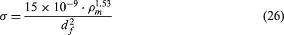
In Garai’s model, the unit of fiber diameter d is in meters (ranged from 18 to 48 µm), and bulk density ranged from 12 to 60 kg/m3. In Kino’s model, d is the fiber diameter in meters (6–39 µm), ρm is bulk density in kg/m3 (28–101 kg/m3). Ballagh [14] has investigated the relationship between the airflow resistivity, bulk density and fiber diameter of wool. The diameter d of wool is generally ranged from 22 to 35 µm, while the bulk density ρm ranged from 13 to 90 kg/m3. Airflow resistivity could be calculated by the following equation
As shown in equations (24) to (26), airflow resistivity is inversely proportional to the square of the fiber diameter for glass fiber and polyester fiber. However, the airflow resistivity of woolen fibrous materials is inversely proportional to the fiber diameter of wool. The difference is due to the fact that the diameter of wool fiber is of the same order as the thickness of the viscous and thermal boundary layers, whereas glass and polyester fibers have an order of magnitude smaller than these boundary layers. Compared with fiberglass and other non-isotropic fibrous materials, woolen fiber assembly is isotropic and there is no significant airflow resistivity deviation in different directions. Voronina and Horoshenkov [81] have also developed a model to describe the airflow resistivity of granular media. In their work, a classification method of granular media has been proposed, which is based on the characteristic particle dimension and porosity. The formulas of airflow resistivity are shown as follows
where De is characteristic particle dimension, Vg is the number of particles in a specific unit volume and η is the dynamic viscosity of air. As reported by Mechel [82], the airflow resistivity of bulk fibrous materials with different fiber diameter could be expressed as follows
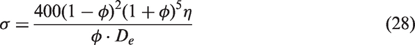
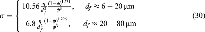
It can be seen from equation (30) that the model is based on different coefficients when calculating airflow resistivity. Allard and Atalla [1] have also reported a method to calculate the airflow resistivity through viscous characteristic length [83]. These formulas are shown as follows
where Λ is the viscous characteristic length, Lf is the total length of fibers per unit volume, Rf is the fiber radius, η is the dynamic viscosity of air and φ is porosity.
Currently, most of the above-mentioned models are based on fiber diameter and bulk density. The bulk density of fibrous materials is determined by the mean spacing between fibers. In addition, fiber distribution in space also plays an important role in airflow resistance properties. Therefore, it is important to describe the microstructural characteristics of fibrous materials, and then investigate the relationship between airflow resistance and structural parameters. Based on the micro-structural characteristics of fibrous materials, Tarnow [84] has proposed two models to obtain the airflow resistivity of randomly placed parallel cylinders. The calculation process is based on the distance between fibers, and the diameter of fibers. These expressions are shown as follows
where b is the mean spacing between fibers, φ is porosity and η is the dynamic viscosity of air. When airflow is parallel with fibers, airflow resistance could be calculated by equation (34), and when airflow is perpendicular with fibers, airflow resistance could be calculated by equation (35). Furthermore, an equivalent formula for calculating the airflow resistivity of a system that consists of identical parallel fibers was also proposed by Umnova and coworkers [8,85]. The equation of airflow resistivity is shown as follows
where d is the diameter of fibers, and η is the dynamic viscosity of air. Recently, a model to calculate the airflow resistivity of coated glass fiber felts has also been established [86]. The modelling process is based on the fiber diameter and the bulk density of fibrous materials. The formulas could be expressed as follows
where dc is the diameter of composite fiber, d is the diameter of glass fiber, η is the dynamic viscosity of air, ρ is the density of fibrous materials, ρr is the density of resin and ρg is the density of glass fiber. It has been found that this model performs better than Bies and Hansen’s model in predicting the airflow resistance of fibrous materials when the bulk density is relatively low. Recently, it has been reported that airflow resistivity could also be extracted from Sabine absorption coefficients. The calculation process is based on Miki’s model and the frequency-independent effects of acoustic waves. Airflow resistivity could be predicted according to the known thickness and air gap distance behind the sound absorber. This method is applicable for both extendedly reacting absorber with air gap and locally reacting absorber [87,88].
A summary of reported models to predict airflow resistance is listed in Table 3. Compared with the experimental methods of measuring airflow resistance, the application of calculation models is generally limited. Different models are usually suitable for different fibers, for instance glass fibers, rock wool and polyester fibers. Moreover, according to reported studies [86,89], there is usually a prediction bias between the calculated and measured airflow resistance. A model is usually insufficient to represent the true value of airflow resistivity, which can be mainly attributed to the variation in bulk density and porosity. On the other hand, these equations are only valid for uniform fiber diameter media, and it is necessary to account for the distribution in the fiber diameter for blended fibers. Among various models, the proposed Kozeny-Carman model presents a theoretical link between the airflow resistivity, fiber diameter and bulk material density for laminar airflow. To study the airflow resistance effects on acoustic properties, both experimental and modeling methods are necessary. The calculation of airflow resistivity is also beneficial to investigate the relationship between the structural characteristics and acoustical properties of fibrous materials.
A summary of different models to calculate the airflow resistance of various fibrous materials and their applications.
No.
Materials
Premise and application of model
Reference
1
Glass fiber and rockwool
Fiber diameter is less than 15 µm, bulk density ranged from 23 to 74 kg/m3
Currently, normal incidence sound absorption is an important index to evaluate the noise-reduction property of fibrous materials. Using impedance tube method, the absorption coefficients can be measured through the surface impedance of test samples. Furthermore, airflow resistance is also effective to predict the normal incidence sound absorption coefficients based on reported models. The prediction of sound absorption through airflow resistance has the advantage of time-saving in comparison with experimental measurements, and it is also benefit to the design of acoustic materials. Acoustic materials could be classified as bulk materials and sheet materials according to the comparison between sample thickness and sound wavelength. The thickness of sheet materials is smaller than wavelength, while the thickness of bulk materials is generally larger than wavelength [93–95]. It has been reported that the sound propagation in sheet materials is mainly determined by viscous effects and areal density, while viscous and thermal effects and the solid frame density control the acoustic behavior of bulk materials [96]. Currently, a series of empirical methods related to airflow resistance was established. For instance, Delany and Bazley [17] have proposed a facile empirical model consists of characteristic impedance Z = R + jX and propagation constant Γ = Α + jΒ. R and X are the real part and imaginary part of characteristic impedance Z, respectively; Α and Β are the real part and imaginary part of propagation constant Γ, respectively. In Delany-Bazley’s model, fibrous layer was considered as bulk materials with the rigid frame media, so that the airflow resistivity is sufficient to describe the characteristic impedance and the propagation constant. Two equations are shown as follows
where f is the frequency of sound wave in hertz, ρ0 is the density of air, c0 is the velocity of sound in air (m/s), σ is the airflow resistivity and c1–c8 are the parameters corresponding to different fibrous materials. In addition, the summary of various empirical models to predict sound absorption coefficients based on airflow resistivity was reported in previous reviews [97,98]. The normal sound absorption coefficients α could be calculated by Zwikker-Kosten’s theory, as follows
where Zs is surface characteristic impedance and d is sample layer thickness. Based on Delany-Bazley’s model, Miki [99,100] has established a new general model to predict sound absorption coefficients by simultaneously considering porosity φ, tortuosity α∞ and airflow resistivity σ
Compared with the initial Delany-Bazley’s model, Miki’s model has better applicability for various kinds of porous materials. Furthermore, airflow resistivity also plays an important role in Johnson-Champoux-Allard (JCA) model to characterize the acoustical properties of fibrous materials. The formula of JCA model is based on five parameters, including airflow resistivity, porosity, tortuosity, viscous characteristic length and thermal characteristic length. These expressions are shown as follows
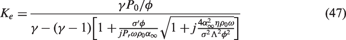
JCA model consisted of dynamic bulk density to describe the effects of air viscose resistance and dynamic bulk modulus to characterize thermal conduction. In addition, some other acoustical models such as Attenborough [101], Komatsu [102] and Kino-Ueno [77,78] are also based on airflow resistivity. Furthermore, Lafarge and coworkers [103] have established a modified JCA-Lafarge model to characterize the acoustical properties of fibrous materials, which is related to the five parameters of JCA model and also the static thermal permeability k′ [60]. A summary of airflow resistivity σ in the applications of predicting sound absorption properties are shown in Figure 4. It could be seen that airflow resistivity is essential to characterize the acoustical properties of bulk fibrous materials.
Diagram of several acoustical models based on airflow resistivity.
Airflow resistance is also a basic parameter for sheet acoustic materials, such as woven fabric, non-woven fabric and perforated plate. For instance, when a perforated plate is backed with an air gap, the sound absorption properties is mainly determined by its airflow resistivity. The normal surface impedance Zs and sound absorption coefficient α of the perforated plate absorber could be calculated from airflow resistivity σ, the equations are shown as follows [75]
where d is the thickness of perforated fabric and La is the thickness of air gap. ρ0, c0 and k0 are the density, the speed of sound and the acoustical wavenumber of air, respectively. Z0 is the characteristic impedance of air and Zb is the surface impedance of the air gap. It has been found that the sound absorption properties could be optimized by manipulating the relationship between specific airflow resistance and air characteristic impedance Z0 [75]. Pieren [76] has established a model to predict the optimal specific airflow resistance of fabric under certain air gap distance
where m is the surface mass density (kg/m2) of fabric. It could be seen that the effects of surface mass density on optimal specific airflow resistance is significant for lightweight fabrics. In addition, a theoretical model has also been developed to investigate the sound absorption of multi-layer sintered fibrous metals on the basis of dynamic airflow resistivity. The model provides the feasibility to control the acoustic wave propagation in sintered fibrous materials by optimizing the gradient distributions of key physical parameters [104–106]. Moreover, airflow resistance is also an effective tool to investigate the structures of fibrous materials, and the high standard deviation of measured airflow resistance could indicate the inhomogeneity of natural fibers [70]. Lu and coworkers [107] have studied the sound absorption properties of sand panels with different airflow resistivity, the sound absorption peak was affected by airflow resistivity. The optimal airflow resistivity for sound absorption could also be obtained through self-assembled graphene oxide films interconnected with the limbs of the melamine skeleton [108].
Reverberation chamber sound absorption
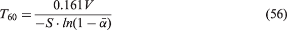
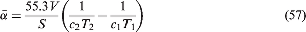
Reverberation chamber sound absorption refers to the diffuse-field absorption coefficients instead of normal incidence absorption coefficient. It is more practical for both architectural and environmental applications, the sound arrives at the materials’ surface from arbitrary angles and hence the measured results are more representative under practical conditions. However, reverberation chamber method requires large samples of the material under measurement as it is difficult to obtain accurate data from small samples. The reverberation chamber absorption of acoustic energy is generally determined by the sound absorption materials at the boundary, and it is closely related to airflow resistance parameter. Reverberation time could be manipulated through placing acoustic materials on the ceiling or wall of a room. Currently, both Sabin equation (equation (55)) and Eyring equation (equation (56)) are widely used to calculate the reverberation time of a room [8,109]. The expressions of these two models are shown as follows
where V is room volume (m3), S is room surface area (m2) and is the average diffuse-field sound absorption coefficients of the room. It could be seen that the sound absorption properties of materials play an important role in reverberation chamber measurement. As specified in ISO 354 [110], the statistical absorption coefficients could be measured by the reverberation chamber method and the formula is expressed as follows
where c1 and T1 are the velocity of acoustic wave and the reverberation time for an empty case, while c2 and T2 are the velocity of acoustic wave and the reverberation time with the specimen installed in the chamber. However, it has been reported that the reproducibility of reverberation room test is poor, which is greatly dependent on the measurement conditions [37,38,88]. In principle, Morse and Bolt [111] have defined a formula of statistical sound absorption coefficient to evaluate the fraction of sound waves incidence from all angles. This formalized method has been the basis for estimating diffuse-field sound absorption from acoustic impedance. The formula is shown as follows
where θ is the incidence angle of acoustic waves and α(θ) could be calculated by the following equations [76,112]
where Zs is the surface impedance and it could be calculated from airflow resistance, Z0 is the characteristic impedance of air and rc is the complex reflection coefficient of the sound absorber. As it is known to all, reverberation chamber sound absorption measurement is complicated and expensive, and the reproducibility is also poor [113–116]. According to above-mentioned studies, it is applicable to predict the reverberation chamber sound absorption behavior of fibrous materials based on airflow resistance.
Conclusion
This review has presented a comprehensive survey concerning the measurements, calculations and applications of airflow resistance. Firstly, we have reviewed the development history and current status of airflow resistance; the principles and procedures of different test methods were also compared. It can be seen that the widely used direct airflow method was facile to measure airflow resistance. Alternative airflow method has the advantage of high accuracy, while acoustical method can simultaneously measure several parameters. Secondly, different models of calculating airflow resistance are summarized. The majority of these models are based on the empirical relationships, and different models are generally established for limited fibers. In addition, these models are also beneficial to inversely investigate the micro-structural characteristics of fibers. Thirdly, airflow resistance can provide sufficient information for engineering acoustics and noise control. This work has gathered the applications of airflow resistance in impedance tube measurements and room acoustics. In conclusion, it is an essential topic to measure the airflow resistance through both experimental and calculation models. It is hoped that this review can provide a helpful guide for the acoustical applications of fibrous materials.
Footnotes
Acknowledgement
The scholarship of Special Excellent Doctoral Candidate International Visit Program of Donghua University is acknowledged.
Declaration of conflicting interests
The author(s) declared no potential conflicts of interest with respect to the research, authorship, and/or publication of this article.
Funding
The author(s) disclosed receipt of the following financial support for the research, authorship, and/or publication of this article: This work was supported by the Fundamental Research Funds for the Central Universities (BCZD2018005).
Appendix
References
1.
AllardJFAtallaN. Propagation of sound in porous media: modelling sound absorbing materials, 2nd edn. Hoboken, NJ, USA: John Wiley & Sons, Ltd, 2009.
2.
BiesDAHansenCH. Flow resistance information for acoustical design. Appl Acoust1980; 13: 357–391.
SoltaniPAzimianMWiegmannA, et al.Experimental and computational analysis of sound absorption behavior in needled nonwovens. J Sound Vibr2018; 426: 1–18.
5.
ISO 9053: 1991. Acoustics–materials for acoustical applications–determination of airflow resistance, International Standards Organization, Geneva, Switzerland, 1991.
6.
TaoJCWangPQiuXJ, et al.Static flow resistivity measurements based on the ISO 10534.2 standard impedance tube. Build Environ2015; 94: 853–858.
Beranek LL and Vér IL. Noise and vibration control engineering: principles and applications. In: IL Ver and LL Beranek (eds) Sound-absorbing materials and sound absorbers. New York: Wiley, 2006.
9.
HoroshenkovKVGrobyJPDazelO. Asymptotic limits of some models for sound propagation in porous media and the assignment of the pore characteristic lengths. J Acoust Soc Am2016; 139: 2463–2463.
10.
TangXZhangXZhuangX, et al.Acoustical analysis of corduroy fabric for sound absorption: Experiments and simulations. J Industr Text. 2018; 48: 201–220. DOI: 10.1177/1528083717725912.
11.
SeddeqHSAlyNMMarwaAA, et al.Investigation on sound absorption properties for recycled fibrous materials. J Industr Text2013; 43: 56–73.
12.
PaşayevNKocatepeSMaraşN. Investigation of sound absorption properties of nonwoven webs produced from chicken feather fibers. J Industr Text. 2019; 48: 1616–1635. DOI: 10.1177/1528083718766843.
13.
YangTXiongXMishraR, et al.Study on sound absorption performance and transmission behavior of perpendicular-laid nonwovens. J Fiber Bioeng Informat2017; 10: 173–185.
14.
BallaghKO. Acoustical properties of wool. Appl Acoust1996; 48: 101–120.
15.
PutraAOrKHSelamatMZ, et al.Sound absorption of extracted pineapple-leaf fibres. Appl Acoust2018; 136: 9–15.
16.
LimZYPutraANorMJM, et al.Sound absorption performance of natural kenaf fibres. Appl Acoust2018; 130: 107–114.
LiuXYanXZhangH. Sound absorption model of kapok-based fiber nonwoven fabrics. Text Res J2015; 85: 969–979.
19.
LiuXYanXZhangH. Effects of pore structure on sound absorption of kapok-based fiber nonwoven fabrics at low frequency. Text Res J2016; 86: 739–748.
20.
GaraiMPompoliF. A simple empirical model of polyester fibre materials for acoustical applications. Appl Acoust2005; 66: 1383–1398.
21.
OthmaniCTaktakMZeinA, et al.Experimental and theoretical investigation of the acoustic performance of sugarcane wastes based material. Appl Acoust2016; 109: 90–96.
22.
ArenasCLeivaCVilchesLF, et al.Approaching a methodology for the development of a multilayer sound absorbing device recycling coal bottom ash. Appl Acoust2017; 115: 81–87.
23.
BansodPVMohantyAR. Inverse acoustical characterization of natural jute sound absorbing material by the particle swarm optimization method. Appl Acoust2016; 112: 41–52.
24.
D'AlessandroFAsdrubaliFMencarelliN. Experimental evaluation and modelling of the sound absorption properties of plants for indoor acoustic applications. Build Environ2015; 94: 913–923.
25.
SwearingenMEWhiteMJGuertinPJ, et al.Influence of a forest edge on acoustical propagation: experimental results. J Acoust Soc Am2013; 133: 2566–2575.
26.
WangJJLeistnerPLiXD. Prediction of sound absorption of a periodic groove structure with rectangular profile. Appl Acoust2012; 73: 960–968.
27.
BottermanBDoudart de la GréeGCHHornikxMCJ, et al.Modelling and optimization of the sound absorption of wood-wool cement boards. Appl Acoust2018; 129: 144–154.
28.
MosanenzadehSGDoutresONaguibHE, et al.A numerical scheme for investigating the effect of bimodal structure on acoustic behavior of polylactide foams. Appl Acoust2015; 88: 75–83.
29.
BrownRLBoltRH. The Measurement of flow resistance of porous acoustic materials. J Acoust Soc Am1942; 13: 337–344.
ASTM-C522-03. Standard test method for airflow resistance of acoustical materials. American Society for Testing and Materials, 2016.
33.
WangCNTorngJH. Experimental study of the absorption characteristics of some porous fibrous materials. Appl Acoust2001; 62: 447–459.
34.
SoltaniPZerrebiniM. The analysis of acoustical characteristics and sound absorption coefficient of woven fabrics. Text Res J2012; 82: 875–882.
35.
SoltaniPZarrebiniM. Acoustic performance of woven fabrics in relation to structural parameters and air permeability. J Text Instit2013; 104: 1011–1016.
36.
Kucukali-OzturkMOzden-YenigunENergisB, et al.Nanofiber-enhanced lightweight composite textiles for acoustic applications. J Industr Text2017; 46: 1498–1510.
37.
HoroshenkovKVKhanABecotFX, et al.Reproducibility experiments on measuring acoustical properties of rigid-frame porous media (round-robin tests). J Acoust Soc Am2007; 122: 345–353.
38.
PompoliFBonfiglioPHoroshenkovKV, et al.How reproducible is the acoustical characterization of porous media?J Acoust Soc Am2017; 141: 945–955.
39.
YilmazNDPowellNBBanks-LeeP, et al.Multi-fiber needle-punched nonwoven composites: effects of heat treatment on sound absorption performance. J Industr Text2013; 43: 231–246.
40.
ArumugamVMishraRMilitkyJ, et al.Thermo-acoustic behaviour of 3D knitted spacer fabrics. Fib Polym2015; 16: 2467–2476.
41.
RamamoorthyMPisalAARengasamyRS, et al.In-situ synthesis of silica aerogel in polyethylene terephthalate fibre nonwovens and their composite properties on acoustical absorption behavior. J Porous Mater2018; 25: 179–187.
42.
DragonettiRIannielloCRomanoRA. Measurement of the resistivity of porous materials with an alternating air-flow method. J Acoust Soc Am2011; 129: 753–764.
43.
Norsonic. Airflow resistance measurement system Nor 1517A, https://web2norsoniccom/ (accessed 5 October 2018).
44.
YanivSL. Impedance tube measurement of propagation constant and characteristic impedance of porous acoustical material. J Acoust Soc Am1973; 54: 1138–1142.
45.
WoodcockRHodgsonM. Acoustic methods for determining the effective flow resistivity of fibrous materials. J Sound Vibr1992; 153: 186–191.
46.
del ReyRAlbaJArenasJP, et al.Evaluation of two alternative procedures for measuring airflow resistance of sound absorbing materials. Arch Acoust2013; 38: 547–554.
47.
Maderuelo-SanzRGómez EscobarVMeneses-RodríguezJM. Potential use of cigarette filters as sound porous absorber. Appl Acoust2018; 129: 86–91.
48.
RenMZJacobsenF. A method of measuring the dynamic flow resistance and reactance of porous materials. Appl Acoust1993; 39: 265–276.
49.
DoutresOSalissouYAtallaN, et al.Evaluation of the acoustic and non-acoustic properties of sound absorbing materials using a three-microphone impedance tube. Appl Acoust2010; 71: 506–509.
50.
PicardMASolanaPUrchueguiaJF. A method of measuring the dynamic flow resistance and the acoustic measurement of the effective static flow resistance in stratified rockwool samples. J Sound Vibr1998; 216: 495–505.
51.
HoroshenkovKV. A review of acoustical methods for porous material characterisation. Int J Acoust Vibr2017; 22: 92–103.
52.
NireshJNeelakrishnanSRaniSS, et al.Analysis of static flow resistivity of a modified impedance tube. Circuit Syst2016; 07: 2253–2261.
53.
NishizuTTomatsuEKatsunoN. Airflow resistance measurement for a layer of granular material based on the Helmholtz resonance phenomenon. Biosci Biotechnol Biochem2017; 81: 823–830.
54.
IannaceGIannielloCMaffeiL, et al.Steady-state air-flow and acoustic measurement of the resistivity of loose granular materials. J Acoust Soc Am1999; 106: 1416–1419.
55.
NarangPP. Material parameter selection in polyester fibre insulation for sound transmission and absorption. Appl Acoust1995; 45: 335–358.
56.
WassilieffC. Sound absorption of wood-based materials. Appl Acoust1996; 48: 339–356.
57.
TarnowV. Measured anisotropic air flow resistivity and sound attenuation of glass wool. J Acoust Soc Am2002; 111: 2735–2739.
58.
RamisJAlbaJdel ReyR, et al.New absorbent material acoustic based on kenaf's fibre. Mater De Constr2010; 60: 133–143.
ManningJPannetonR. Acoustical model for Shoddy-based fiber sound absorbers. Text Res J2013; 83: 1356–1370.
61.
ArenasJPRebolledoJdel ReyR, et al.Sound absorption properties of unbleached cellulose loose-fill insulation material. Bioresources2014; 9: 6227–6240.
62.
NavacerradaMADiazCFernandezP. Characterization of a material based on short natural fique fibers. Bioresources2014; 9: 3480–3496.
63.
del ReyRBertoLAlbaJ, et al.Acoustic characterization of recycled textile materials used as core elements in noise barriers. Noise Contr Eng J2015; 63: 439–447.
64.
JonesPWKessissoglouNJ. Simplification of the Delany–Bazley approach for modelling the acoustic properties of a poroelastic foam. Appl Acoust2015; 88: 146–152.
65.
KinoN. Further investigations of empirical improvements to the Johnson-Champoux-Allard model. Appl Acoust2015; 96: 153–170.
66.
PengLMSongBQWangJF, et al.Mechanic and acoustic properties of the sound-absorbing material made from natural fiber and polyester. Adv Mater Sci Eng2015; 274913: 1–5.
67.
DattPKapilJCKumarA, et al.Experimental measurements of acoustical properties of snow and inverse characterization of its geometrical parameters. Appl Acoust2016; 101: 15–23.
68.
KhanAMohamedMAl HaloN, et al.Acoustical properties of novel sound absorbers made from recycled granulates. Appl Acoust2017; 127: 80–88.
69.
RicciardiPTorchiaFBelloniE, et al.Environmental characterisation of coffee chaff, a new recycled material for building applications. Constr Build Mater2017; 147: 185–193.
70.
BerardiUIannaceG. Predicting the sound absorption of natural materials: best-fit inverse laws for the acoustic impedance and the propagation constant. Appl Acoust2017; 115: 131–138.
71.
YangTMishraRHoroshenkovKV, et al.A study of some airflow resistivity models for multi-component polyester fiber assembly. Appl Acoust2018; 139: 75–81.
72.
PengHWangXLiT-T, et al.Study on preparation, sound absorption, and electromagnetic shielding effectiveness of rigid foam composites. J Sandwich Struct Mater. 2019; 21: 2512–2526. DOI: 10.1177/1099636218755323.
73.
CarmanPC. Fluid flow through granular beds. Chem Eng Res Design1937; 15: S32–S48.
74.
PelegrinisMTHoroshenkovKVBurnettA. An application of Kozeny-Carman flow resistivity model to predict the acoustical properties of polyester fibre. Appl Acoust2016; 101: 1–4.
75.
ChevillotteF. Controlling sound absorption by an upstream resistive layer. Appl Acoust2012; 73: 56–60.
76.
PierenR. Sound absorption modeling of thin woven fabrics backed by an air cavity. Text Res J2012; 82: 864–874.
77.
KinoNUenoT. Experimental determination of the microand macrostructural parameters influencing the acoustical performance of fibrous media. Appl Acoust2007; 68: 1439–1458.
78.
KinoNUenoT. Evaluation of acoustical and non-acoustical properties of sound absorbing materials made of polyester fibres of various cross-sectional shapes. Appl Acoust2008; 69: 575–582.
79.
KinoNUenoTSuzukiY, et al.Investigation of non-acoustical parameters of compressed melamine foam materials. Appl Acoust2009; 70: 595–604.
80.
KinoNUenoT. Comparisons between characteristic lengths and fibre equivalent diameters in glass fibre and melamine foam materials of similar flow resistivity. Appl Acoust2008; 69: 325–331.
81.
VoroninaNNHoroshenkovKV. A new empirical model for the acoustic properties of loose granular media. Appl Acoust2003; 64: 415–432.
82.
MechelF. Formulas of acoustics, 2nd edn. Berlin: Springer, 2008.
83.
LippitzNRoslerJHinzeB. Potential of metal fibre felts as passive absorbers in absorption silencers. Metals2013; 3: 150–158.
84.
TarnowV. Airflow resistivity of models of fibrous acoustic materials. J Acoust Soc Am1996; 100: 3706–3713.
85.
UmnovaOAttenboroughKLiKM. Cell model calculations of dynamic drag parameters in packings of spheres. J Acoust Soc Am2000; 107: 3113–3119.
86.
YangYChenZ. A model for calculating the air flow resistivity of glass fiber felt. Appl Acoust2015; 91: 6–11.
87.
JeongCH. Converting Sabine absorption coefficients to random incidence absorption coefficients. J Acoust Soc Am2013; 133: 3951–3962.
88.
JeongCH. Predicting the Sabine absorption coefficients of fibrous absorbers for various air backing conditions with a frequency-dependent diffuseness correction. J Acoust Soc Am2016; 140: 1498–1501.
89.
HurrellAIHoroshenkovKVPelegrinisMT. The accuracy of some models for the airflow resistivity of nonwoven materials. Appl Acoust2018; 130: 230–237.
90.
BiesDAHansenCH. Engineering noise control: theory and practice, 4th edn. London and New York: Spon Press, 2009.
91.
YangWDLiY. Sound absorption performance of natural fibers and their composites. Sci China Technol Sci2012; 55: 2278–2283.
92.
RamisJdel ReyRAlbaJ, et al.A model for acoustic absorbent materials derived from coconut fiber. Mater De Constr2014; 64: e008–e008.
93.
BarburskiMBlaszczakJRPawliczakZ. Influence of designs of weaves on acoustic attenuation of fabrics. J Industr Text. 2019; 49: 33–45. DOI: 10.1177/1528083718769945.
94.
Kucukali-OzturkMNergisBCandanC. Design of layered structure with nanofibrous resonant membrane for acoustic applications. J Industr Text. 2018; 47: 1739–1756. DOI: 10.1177/1528083717708483.
95.
TholkappiyanESaravananDJagasthithaR, et al.Prediction of acoustic performance of banana fiber-reinforced recycled paper pulp composites. J Industr Text2016; 45: 1350–1363.
96.
MoholkarVSWarmoeskerkenMM. Acoustical characteristics of textile materials. Text Res J2003; 73: 827–837.
97.
TangXYanX. Acoustic energy absorption properties of fibrous materials: a review. Compos A Appl Sci Manufact2017; 101: 360–380.
98.
DunneRDesaiDSadikuR. A review of the factors that influence sound absorption and the available empirical models for fibrous materials. Acoust Aust2017; 45: 1–17.
99.
MikiY. Acoustical properties of porous materials-modifications of Delany-Bazley models. J Acoust Soc Jpn (E)1990; 11: 19–24.
100.
MikiY. Acoustical properties of porous materials-generalizations of empirical models. J Acoust Soc Jpn (E)1990; 11: 25–28.
KomatsuT. Improvement of the Delany-Bazley and Miki models for fibrous sound-absorbing materials. Acoust Sci Technol2008; 29: 121–129.
103.
LafargeDLemarinierPAllardJF, et al.Dynamic compressibility of air in porous structures at audible frequencies. J Acoust Soc Am1997; 102: 1995–2006.
104.
MengHAoQBTangHP, et al.Dynamic flow resistivity based model for sound absorption of multi-layer sintered fibrous metals. Sci China Technol Sci2014; 57: 2096–2105.
105.
NingJFZhaoGP. Sound absorption characteristics of multilayer porous metal materials backed with an air gap. J Vibr Contr2016; 22: 2861–2872.
106.
LippitzNBlechCLangerS, et al.Identification of material parameters for the simulation of acoustic absorption of fouled sintered fiber felts. Materials2016; 9: 1–13.
107.
LuSXuWGChenYX, et al.An experimental study on the acoustic absorption of sand panels. Appl Acoust2017; 116: 238–248.
108.
NineMJAyubMZanderAC, et al.Graphene oxide-based lamella network for enhanced sound absorption. Adv Funct Mater2017; 27: 1703820–1703820.
109.
CoxTJD'AntonioP. Acoustic absorbers and diffusers: theory, design and application, New York: CRC Press, 2009.
110.
ISO 354. Acoustics-measurement of sound absorption in a reverberation room, International Standards Organization, Geneva, Switzerland, 2003.
111.
MorsePMBoltRH. Sound waves in rooms. Rev Modern Phys1944; 16: 69–150.
112.
KangJFuchsHV. Predicting the absorption of open weave textiles and micro-perforated membranes backed by an air space. J Sound Vibr1999; 220: 905–920.
113.
JeongC-H. Non-uniform sound intensity distributions when measuring absorption coefficients in reverberation chambers using a phased beam tracing. J Acoust Soc Am2010; 127: 3560–3568.
114.
JeongCH. Kurtosis of room impulse responses as a diffuseness measure for reverberation chambers. J Acoust Soc Am2016; 139: 2833–28341.
115.
SakagamiKUyamaTMorimotoM, et al.Prediction of the reverberation absorption coefficient of finite-size membrane absorbers. Appl Acoust2005; 66: 653–668.
116.
MartellottaFCirilloE. Experimental studies of sound absorption by church pews. Appl Acoust2009; 70: 441–449.