
Abstract
The aim of this study is to investigate the effect of spinneret design parameters on cross-sectional shape and mechanical performance characteristics of coaxial composite filaments. A number of different cross-sectional-shaped metal/polymer core/sheath coaxial composite filaments were developed by changing spinneret design parameters. The cross-sectional shapes obtained were circular, rectangular, triangular and elliptical shapes. The mechanical performance of filaments was evaluated for application in sensors and actuators. The change of cross-sectional shape significantly influences mechanical properties of developed filaments which express their vulnerability during applied stresses in their life cycle.
Keywords
Introduction
A composite material is composed of two or more dissimilar materials having peculiar forms at macroscale level with distinct recognizable interfaces between them [1]. A filament fabricated with two or more different materials is termed as composite filament. These materials may include different polymers [2–5], metals [6,7], fibres [8,9] and coatings [10–13] for the fabrication of composite filaments. These filaments can be used for wide spread applications including electrical conductivity [14], thermal conductivity [4,5], UV protection, self-cleaning, antimicrobial and flame retardancy, etc. [15]. These technical filaments can be used in functional textiles as smart materials [16,17]. The introduction of carbon fibres, metal filaments or coating, and piezoelectric materials in composite filaments brings these structures in class of intelligent SMART textiles [18]. The SMART textiles are supposed to be developed with wholly functional monofilaments rather than just integration of modern technologies in conventional textile substrates. The development of intelligent monofilament promises for innovative SMART textile applications. These intelligent monofilaments can only be fabricated by the introduction of composite filament technology in which each material contributes its properties in the final structure having diversified characteristics. The monofilaments having the ability to sense and react to some external stimuli are called as intelligent monofilaments. The smart applications include robotics, optics, computers, underwater and electro-acoustic transducers, ultrasonic, an invasive medical robot for diagnostics and microsurgery, potential artificial muscle actuator, pressure sensors, and sensors to prevent blockages and monitor vascular grafts [19–21].
A composite filament comprising a core and sheath, sharing the same central axis, is called coaxial composite filament. These filaments have wide-spread applications which include, thermal conductivity, electrical conductivity [22,23], high strength applications [24], electromagnetic interference shielding [25,26] and sensors and actuators [3,7]. Coaxial composite filaments can be fabricated through several techniques including wet extrusion [10], melt extrusion [27,28], and melt printing [29]. The performance properties of the filament depend on the extrusion parameters including processing parameters and spinneret design. The extrusion die design is the crucial factor affecting the performance properties of coaxial composite filaments. The value of any process depends upon its economical, efficient and reliability factors. The conductive coaxial composite filaments found in literature are based on doped polymer multilayer structures which have non-uniform layers over the radial positions [3,30]. The cores were developed with doped polymer substrates which provided maximum conductivity value of ≈1.03 × 10+1 S/cm6. The conductivity further decreased sharply during stretching processes. The working efficiency of conductive filament used for applications in electrical conductivity, electromagnetic shielding effectiveness, thermal conductivity, and sensor and actuator is significantly dependent upon electrical resistance of constituent materials. In consideration of all these requirements, a coaxial composite filament developed with metallic core filament will be a good option for wide spread applications in SMART textiles.
The load-bearing capacity of a material is an evaluation of its performance characteristic, which it can withstand during its usage. The composite filaments used for multiple applications in SMART textiles must comply with the mechanical strength requirements. The mechanical analysis of the textile material is carried out by stress–strain behaviour. The influence of polymer structure and drawing ratio are significant factors for the mechanical behaviour of a material. High chain orientations are achieved in filaments having higher drawn ratio which resultantly achieve more strength and modulus, whereas the filaments which are drawn at low levels have less orientation with little stiffness and more dye penetration. The results from stress–strain curves for polyester filaments, manufactured from same spun process with different drawn ratio, showed that breaking stress increases significantly at higher elongation values [31]. In addition, the increase in draw ratio resulted in decrease in extension.
The tensile strength and modulus of the composite filament significantly increased by increase in melt draw ratio of coaxial composite filament [28]. This increase in the mechanical properties is attributed to the increase in crystallinity as well as crystal orientation in the structure. The thermal annealing process also affected the mechanical properties of fiber [27]. It was reported that the elastic limits and tensile strength of the coaxial composite filament were superior from the individual strength of the polymer filament drawn under the same conditions [27], which indicated that the load was uniformly applied over the core of composite filament. The reason for this increase in the mechanical behaviour was probably the reduction of stress concentration by the elastic nature of the sheath.
The non-uniform cooling process of the filament develops skin-core structure formation. The molecular chains at the surface are more regular and oriented than at the inner region of the filament, developed with high speed spinning, which is due to non-uniform solidification. The oriented surface molecular chains support spinning stress, while the interior chains are disoriented and relaxed due to higher temperatures [21]. During mechanical stress, the skin is prone to more stress and breaks first, and hence the filament rupture occurs before the inner molecular chains contribute much resistance. The overall tenacity and fibre strength are lost as a result.
A circular coaxial composite filament developed with piezoelectric polymer as sheath on copper core filament was mechanically tested to analyse its performance properties. It was observed that core and sheath material have good adherence between their interfaces [7]. The mechanical characterisation of hollow fibre with and without conductive liquid metal alloy was reported by Zhu et al. [32]. The sheath was composed of ultra-stretchable triblock copolymer resin and the core was filled with liquid metal having low viscosity. It was observed that the liquid metal had negligible effects on the mechanical properties of the composite fibre. A tri-layer composite filament developed with conductive polymer nanocomposite core with sheath of thermo-chromic composite polymer was developed by Laforgue et al. [30]. The mechanical stretching of the circular-shaped monofilament resulted in reduction of layer diameter which ultimately reduces the electrical conductivity and hence limits the application of the product [3,10].
Bicomponent fibres were also developed to obtain superior mechanical properties than their precursors with advantage of material's individual properties. Several types of coaxial composite filaments are reported in literature providing enhanced mechanical strength with some other required properties [27,28].
This study is carried out for filaments which find their application particularly as electrical conductive wires and sensors and actuators. There is no study being reported in literature about performance and durability of metal/polymer core/sheath coaxial composite filaments used for different applications. The aim of this research is to analyse the effect of spinneret design parameters and filament cross-sectional shapes on mechanical performance of coaxial composite filaments.
Materials and methods
Materials
Properties of raw material used.

The sheath of composite filament was developed with virgin polyethylene terephthalate polymer used in the form of chips. The conditioning of the polymer chips was done in desiccator Prolabo DV-29 in accordance with ASTM D618-13 standard test method [33]. A temperature of 50 ± 2 ℃ with a pressure of −93.33 MPa was maintained in the chamber for conditioning for 48 h to evaporate the moisture from the polymer. The thermal and rheological specifications of polyester chips are provided in Table 1.
Method
The composite filaments were developed on lab scale conventional melt extrusion machine (FilaTech GmbH, Germany) as schematically shown in Figure 1. It comprised an extrusion device, stretching and cooling region, winding device and control section which controls the entire process. The machine works on piston-based mechanism designed for development of monofilaments with various controlling parameters including, oven temperature selected up to 350 ℃, extrusion speed at range from 0.1 mm/min to 20 mm/min, and winding speed can be varied up to 52 m/min. The spinneret head consists of a cylinder embedded in an oven with spinneret at bottom and a piston at top. The introduction of hollow piston made it possible to feed and deliver copper monofilament through it. A stainless-steel tube was used in the oven for the passage of copper filament. An innovative design of spinneret was developed and used for the production of coaxial composite filaments [34].
Schematic presentation of lab scale melt extrusion machine.
Design of experiments for fabrication of filaments.

The copper monofilament was drawn through the hollow piston, tube and composite spinneret set followed by charging of oven with dried polymer chips. The temperature of the extrusion oven was set at 280 ℃ [18] and resident time for polymer in oven was 5 min. The spinning parameters including piston speed and winding speed were set at 5 mm/min and 35.85 m/min, respectively. The influence of heat treatment during the extrusion was also considered. Therefore, copper monofilament without heat treatment (Cu-NHS) and with heat treatment (Cu-HS) was also fabricated without charging the oven with polymer.
A filament cooling system, having a dimension of 86 cm in height and composed of 16 fans arranged in two arrays, was used to cool down and solidify the filament extruded from the spinneret at room temperature of 25 ℃. The cooling system was attached just below the spinneret. The two arrays of fans on opposite sides of the chamber directed the unidirectional air across the chamber at an angle of 90 ° with the filament for efficient cooling process. The developed coaxial filament was wound on package with winding system.
The samples were cut with sharp razor blade in cold environment to avoid the change in cross-sectional shape followed by metal coating. The metal coating of the filaments was done with gold under argon gas atmosphere in Metalizer E5100, developed by Polaron Equipment Limited. The coating was done at pressure of 0.1 ± 0.05 torr with a current supply of 20 ± 1.0 mA at resident time of 2.0 ± 0.1 min.
Scanning electron microscope S-2360N model manufactured by Hitachi Limited, Japan was used to investigate the cross-sectional shape and dimensions of the filaments at 20 kV voltage. The coaxial filaments obtained have the diameter in the range of 350 µm to 500 µm.
The mechanical characterization of coaxial composite filaments was carried out on MTS 20/M tensile strength tester in accordance with ASTM D2256/D2256M-10 standard test method [35]. The modified gauge length of 25 mm was used while keeping all the other parameters as per standard test procedure. The high sensitive captor of 100 N was used for the measurement of mechanical test. The ultimate application for these filaments is intended for SMART textiles in which the interfacial bonding between the core and sheath layer should remain intact, particularly for sensors and actuators. The other SMART textile applications include electrical signal transmission, thermal conductivity, electromagnetic interference shielding, etc. Therefore, breakage of interface between copper monofilament and sheath polymer was considered as maximum acceptable strength. Filament tenacity, elongation at break and work of rupture were analysed. The strength of polyester filament, heat-set copper monofilament and non-heat-set copper filament was also studied for comparison purposes. A number of 10 replicates for each sample were analysed and mean values were calculated for each parameter.
Results and discussion
Physical characterization
Linear density
The linear density of the composite filament was calculated using the ASTM D 1059 standard test method using short test specimens. A number of 10 specimens were considered for each sample code to determine mean linear density. The graphical representation of linear density versus sample codes is shown in Figure 2.
Actual and theoretical linear density with error percentage of composite filament.
Linear density can also be calculated using the basic equation as follows
This equation can also be written as


To find the volume of individual component


The composite density is calculated using equation (6).

Using the method stated above, the composite density and surface area were calculated individually for each sample. The linear density (Tt
c
) of samples was calculated using equation.(17). The error percentage was calculated using equation (7).

It was observed that the calculated linear density (Tt c ) was quite near to the experimental linear density (Tt a ). The average error obtained was 15.5% which depicts that composite linear density can also be calculated theoretically with significant percent of accuracy. The graphical representation of actual and theoretical linear density is shown in Figure 2.
Mechanical characterization
The obtained filaments have different cross-sectional shapes according to the type of spinneret used [34]. These shapes include elliptical, triangular, rectangular and circular represented by E, T, R and C, respectively, in sample codes for distinction. The SEM images of different cross-sectional shapes are shown in Figure 3. The filaments developed with 1 mm spinneret exit diameter were more regular in cross-sectional shape as compared to other samples in the same series; same trend with less influence was also observed by using 2 mm tube position.
SEM images of fibre cross-sectional shapes, magnification (a is 200×; b, c and d are 150×.
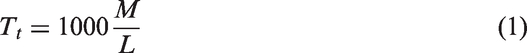
A number of 150 specimens were tested comprising 10 replicates of each sample. The specimen failures near the jaw were discarded and were not used for calculations. The failure of interfacial bonding between core and sheath by macroscopic sliding or slip was considered as the failure of the composite filament as shown in Figure 4. Necking formation started to build up after failure of interfacial bonding up till breaking point. The polymer chains were not elongated in drawing section after extrusion process and hence the composite filament structure may become amorphous in nature which was the reason for formation of necking. This assumption was verified through DSC analysis and degree of crystallinity results obtained for polymer chips and composite filaments were 44% and 9%, respectively. In other cases, filament breaks wholly as complete failure of the composite filament structure as shown in Figure 5. These results were found rare and caused by crystalline regions in the filament, hence also included in the results. Rubber pads were used in the jaws to avoid slippage and damage, and for strong grip.
Failure of composite filaments as necking during tensile test. Failure of composite filaments as breakage during tensile test.
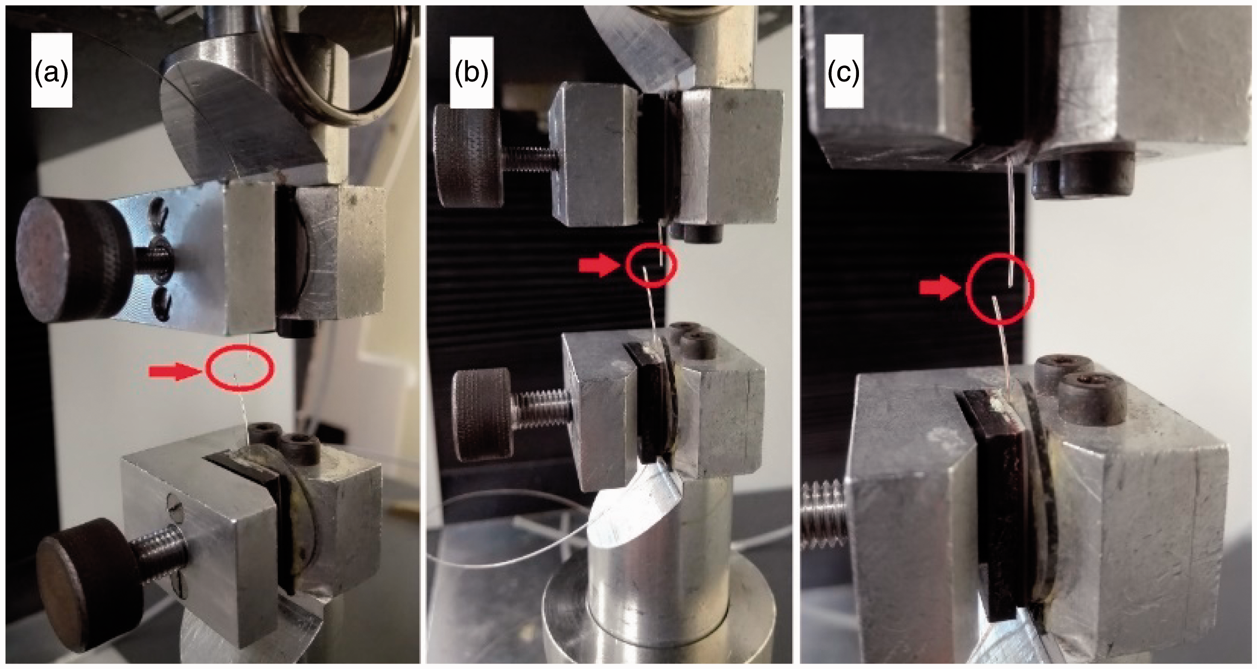
The specific load–extension curves obtained for sample E-1 are shown in Figure 6. The initial straight line obtained showed the elastic region of the filament up till applied force of 1.8 N. After this elastic limit, plastic deformation started in the composite filament. This limit was defined by the copper wire inside the filament. The elastic range of the composite filament was governed by copper wire as shown in Figure 7. The specific load–extension graph of copper wire showed steep slope of elastic limit followed by moderate slope level for plastic deformation up till breaking point. Any deformation caused within the elastic limit can be retreated to its original position. Once applied load increased above elastic limit, the deformation became permanent in the filament. The region from the elastic limit up to maximum load applied is considered as plastic region and was dominantly governed by polyester polymer. The plastic range and necking region of the specific load–extension curve of composite filament were quite similar to the specific load–extension graph observed for polyester filament as shown in Figure 8.
Specific load–extension curves obtained for sample E-1. Specific load–extension curves of copper filament without thermal treatment. Specific load–extension curves of polyester filament.

The polyester specific load–extension curve showed almost zero elastic curve and steep plastic curve up till formation of necking. At the necking point, the specific load–extension curve falls to a lower level steeply due to straightening of polymer chains in the structure. The composite filament curve reduced from the maximum applied load to a lower value, until the de-bonding of interface occurred between core and sheath caused by straightening of polymer chains, with a sharp decrease in applied stress. The maximum load that the filament resists before failure is called tenacity. The mean value of tenacities of the specimens is shown by the horizontal straight line in presented specific load–extension curves.
The arithmetic mean of each parameter obtained by testing 10 specimens of each sample was recorded. The specific breaking stress, breaking extension, elastic modulus and work of rupture were measured for each sample. The standard deviation and coefficient of variation observed between the populations were also calculated. The modulus was calculated at 1% of extension value of specific load–extension curve. The pure polyester filament (PET-F), virgin copper filament with heat treatment (Cu-HS) and without heat treatment (Cu-NHS) were also tested as reference samples.
Tenacity
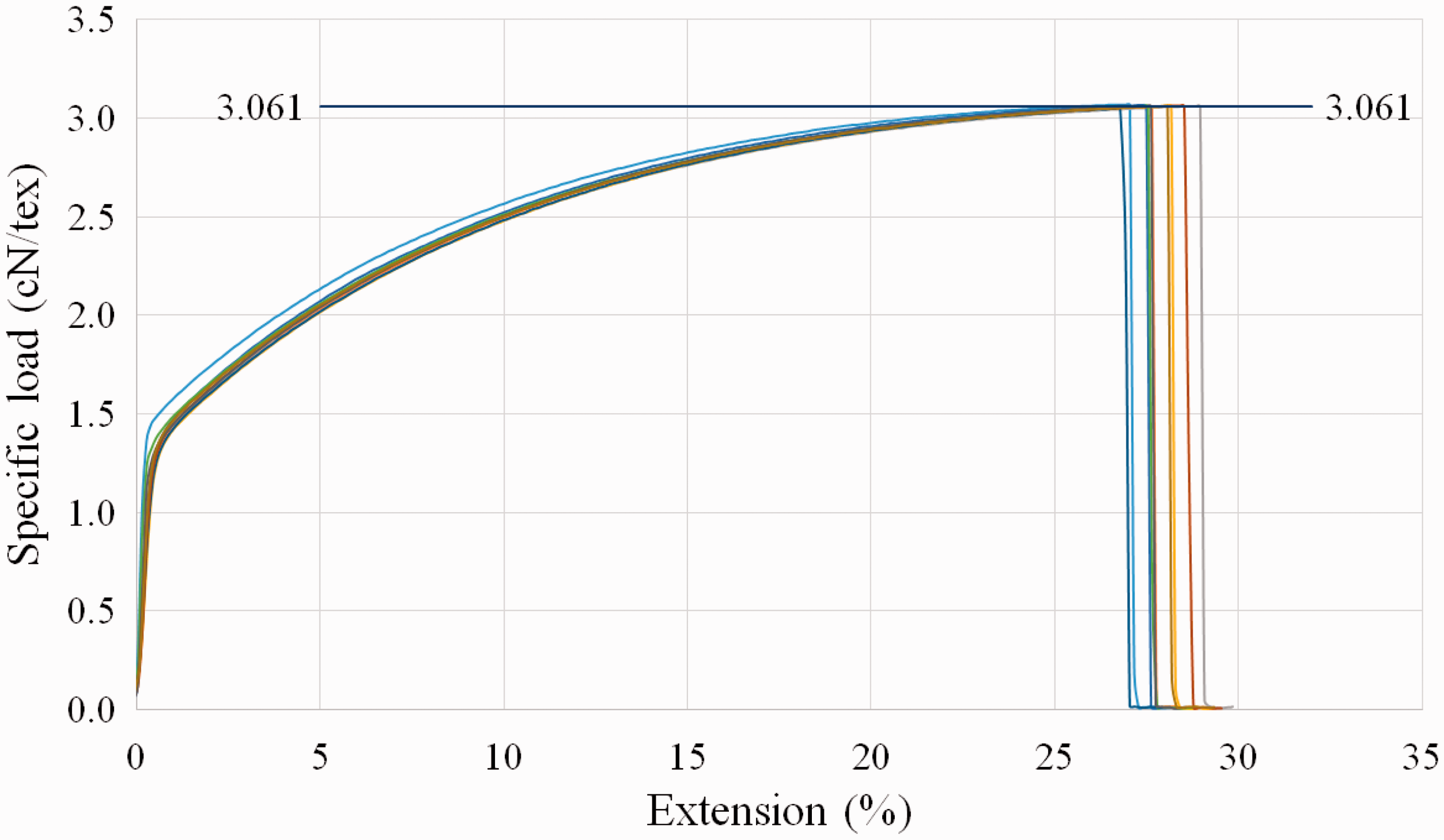
The graphical representation of the arithmetic mean values of tenacity in column graph is shown in Figure 9. The dispersion of data in terms of standard deviation for each sample was also represented as error bar in the same graph. The error bars express 95% confidence interval of each sample. Higher bar explains high potential of variation from mean values.
Graphical representation of tenacity of samples.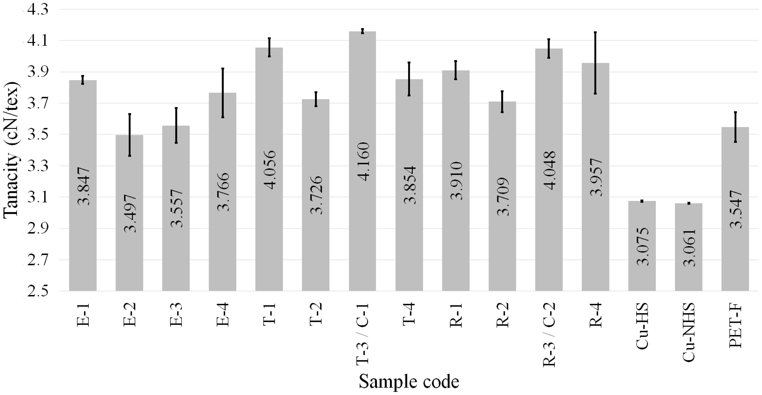
The results showed that the samples E-1 to E-4, developed with spinneret design having 2 number of holes, generally had lower tenacity values as compared to T and R sample series (developed with 3 and 4 holes' spinneret designs respectively). It was observed that T sample series (developed with 3 holes' spinneret design) had higher tenacity values than R sample series (developed with 4 holes' spinneret design). The reason for these differences in values can be explained on the basis of load-bearing capacity of different geometrical structures. It is a general fact that circular-shaped structure distributes the applied force uniformly across the curves, therefore considered as stronger structure followed by triangular, rectangular and elliptical structures. It is assumed that central circular region of the filament is virtually bearing the applied load. Composite filaments of different shapes have different cover percentage in circular ring shape. To estimate this variation, all the composite shapes were used to find the inscribed circular area as shown in Figure 10. The area outside inscribed virtual circular ring is supposed not to impart their role for load bearing during stress application. The calculated area percentage outside circular ring for elliptical, triangular, rectangular and circular cross-sectional-shaped filaments were 20.89%, 14.84%, 8.34% and 1.02%, respectively.
Estimation of area outside circular ring in different cross-sectional-shaped composite filaments.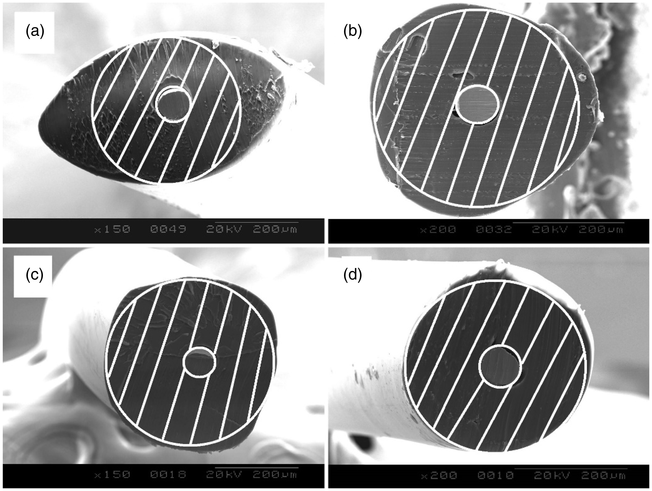
It was observed that the area percentage outside inscribed virtual circular ring was the highest for elliptical followed by triangular and rectangular-shaped filaments in turn. The circular-shaped filament had some area outside circular ring that might be due to angular position of the circular filament during image processing and may also be caused by imperfections in shape. On comparison basis, circular-shaped filament will be considered having zero area outside circular ring and therefore the descending sequence of area outside circular ring will be elliptical, triangular, rectangular and circular-shaped filaments. On contrary, triangular filaments showed higher tenacity values than rectangular-shaped filaments despite their higher area outside circular ring. The reason lies in the fact that triangular shape is second to circular shape for distribution of load during stress application and considered a very stable structure.
The area outside circular ring may have non-aligned molecular chains due to flow geometry during extrusion, therefore considered not playing their role in bearing applied forces on the composite filament. According to theoretical calculations, keeping radius of all inscribed circular rings in different shaped filaments as equal to each other, the equation of area outside circular ring for different shaped filaments is written as follows

This effect can also be explained on the terms of surface area of the filament. The circular-shaped filaments have least value of surface area which increases for rectangular, triangular and elliptical shapes in turn. A compact structure contributes higher in bearing applied load on it. A circular filament shape is most compacted having least surface area and hence can contribute precisely in bearing applied load. Therefore, elliptical cross-sectional shape withstands least amount of load, while circular-shaped filament can withstand high load value.
It was also observed that the spinnerets having 1 mm exit diameter hole have higher tenacity values as compared to 2 mm exit diameter hole. The reason was based on the shape of the filaments which was changed by change in spinneret exit diameter. The spinneret having 1 mm exit diameter provided more regular and circular cross-sectional shape filament as compared to 2 mm exit diameter spinneret. The polymer chains were compacted before extrusion by the spinneret and hence played a vital role in the compactness and shape of the filament. As a result, 1 mm spinneret samples had higher tenacity values.
In addition, the tenacity values for T-series (3 hole's spinneret design) and R-series (4 hole's spinneret design) samples had higher trend of tenacity values due to regular cross-sectional shapes of these samples. It was also observed that composite filaments had higher tenacity values as compared to polyester (PET-F) and copper filaments alone. There was no difference in tenacity value observed between thermally treated (Cu-HS) and non-treated (Cu-NHS) samples of copper filament. The thermal treated samples were developed in the same conditions as composite filament samples were made. In such condition, it is evident that tenacity value of composite filaments synergistically increased from its constituent materials' attribute. Any particular application may require specific filament shape, which may include triangular or elliptical filament design for electrical signal transmission with reduced fabric thickness. In such regards, E1 and T3 provide the best possible solutions with higher mechanical performance characteristics with respect to their cross-sectional shape. Sensors and actuators are developed with perfect circular cross-sectional-shaped filaments; therefore, R3 sample development process will be the best solution for such SMART textile applications.
The experimental value of tenacity was verified with mixture law using associated values of copper and polyester filaments. The theoretical tenacity value was obtained using equation (2).

Comparison of theoretical and experimental tenacity values of composite filaments.

Breaking extension
The percentage ratio of maximum extension before failure to initial length of sample is called breaking extension. It explains the percentage of the extension which a sample can expand up to its failure point. It was observed that the copper filaments have very high breaking extension compared to composite filaments and polyester filaments as shown in Figure 11. The composite filaments did not exhibit the same level of extension due to limitation imposed by polyester. The composite filament had the same level of extension which was exhibited by the polyester filaments. It is quite clear that composite filaments principally adopt the breaking extension limit from polyester sheath. The error bars express the standard deviation of data sets from mean value.
Graphical representation of breaking extension in percentage.
The breaking extension value obtained for samples manufactured from spinneret exit diameter of value 1 mm was significantly higher than 2 mm diameter. Spinneret exit diameter has an influence on regularity of filament. It is concluded that regular surface filaments exhibit higher breaking extension as compared to irregular surface filaments. There was no significant difference observed between different cross-sectional-shaped filaments. Triangular-shaped filaments have a little higher trend of extension values as compared with other cross-sectional-shaped filaments.
Modulus
The modulus was calculated at 1% of extension value because of lower value of elastic limit obtained for composite filaments. It is a measure of the stiffness of the filament which is explained as resistance to extension. It is observed that heat treatment changed the modulus of the copper filament (Figure 12). The non-thermal treated copper filament (Cu-NHS) has less modulus as compared to thermally treated copper filament (Cu-HS). The higher extrusion temperature in the oven heat treated the copper filament during extrusion process. As a result, the modulus of composite filaments was in close proximity to the value of modulus exhibited by heat-treated copper filament. Furthermore, the polyester filament (PET-F) exhibit higher modulus as compared to composite filaments. Owing to inclusion of metal in the polyester filament, the changes in molecular arrangement occur before cooling which reduces the modulus of the composite filament [6].
Graphical representation of elastic modulus of samples.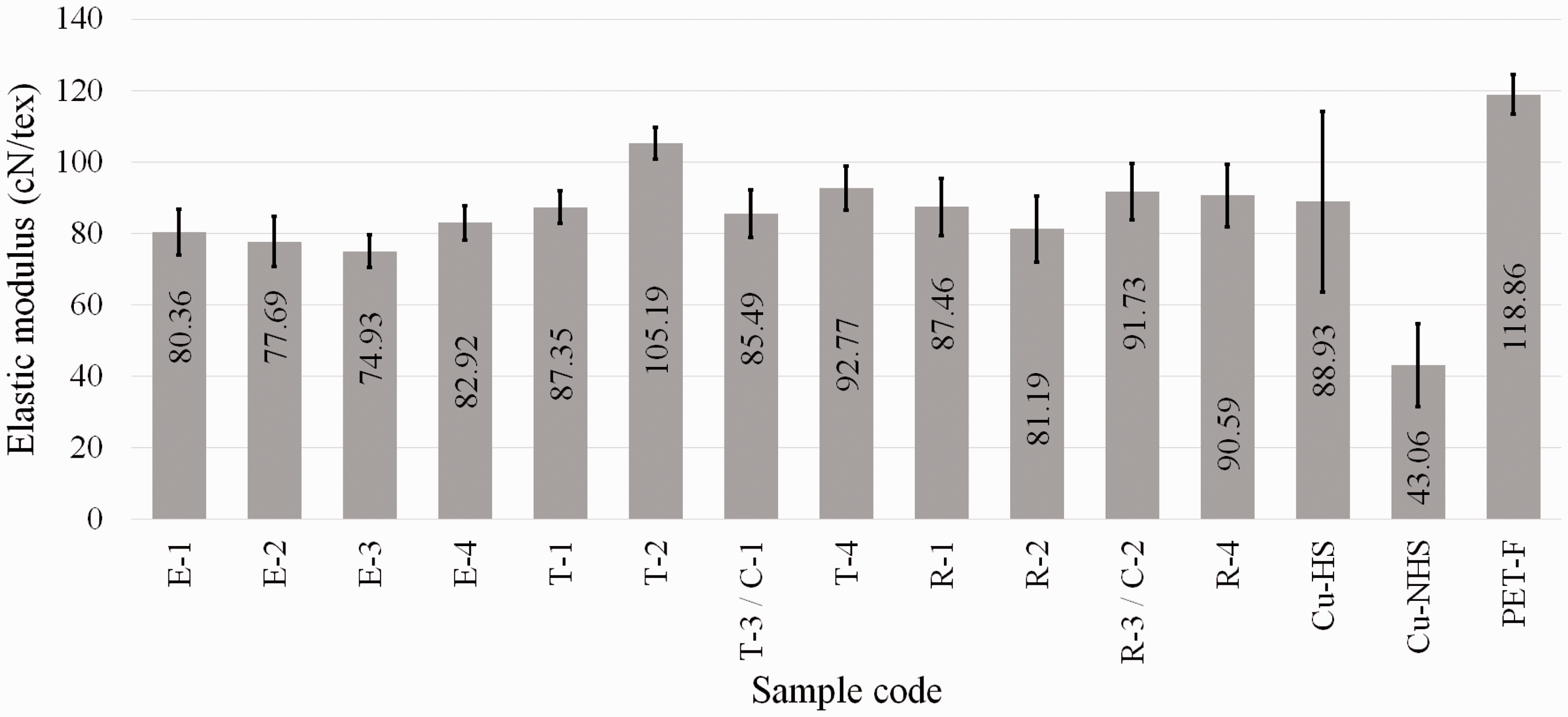
It was observed that regularization of shape from elliptical to circular cross-section improved elastic modulus of composite filaments. The least values of elastic modulus were observed for elliptical cross-sectional shape (E series), while superior values were obtained for circular filaments (C series).
Work of rupture
It is a measure of toughness of the material. It explains the total energy required for failure of the composite filament. The area under the specific load–extension curve is a measure of the work done required to break specific sample. An automatic curve fitting software, Tablecurve 2D version 5.01, was utilized for determine area under the curve. The work of rupture for different samples is shown in Figure 13. The energy required to break polyester filament was quite low as compared with composite filaments. It is observed that the work of rupture increases by the inclusion of copper filament in the polyester polymer.
Graphical representation of work of rupture of different samples.
The specific work of rupture is a ratio of work of rupture to linear density of the material. It is used for comparison basis for materials having different linear densities. The specific work of rupture of the samples is shown in Figure 14. It was observed that copper filament had highest specific work of rupture, and therefore considered as stronger material in composite filament. The differences between copper and composite filament's specific work of rupture are due to high density and very small diameter of copper filament. The results showed that samples manufactured by spinneret exit diameter of 1 mm have significantly higher values of specific work of rupture compared to 2 mm diameter. It expresses that regular structures exhibit higher specific work of rupture values which is explicit verification of the above strength results. It was also observed that cross-sectional shape of the filament also influences specific work of rupture values. Higher trend was observed for circular cross-section filaments followed by triangular, rectangular and elliptical shapes in turn.
Graphical representation of specific work of rupture of samples.
Conclusion
Composite filaments were developed using different spinneret designs and were characterized for their physical and mechanical properties. The physical characterization includes linear density, which were experimentally measured and verified theoretically. The results depict that composite linear density can also be calculated theoretically with significant percentage of accuracy. The mechanical characterization was carried out for performance evaluation of the composite filaments. It is concluded that mechanical performance of coaxial composite filaments changes with change of cross-sectional shapes. The cross-sectional shapes of the composite filaments depend on the spinneret design parameters. It was concluded that elliptical cross-sectional shape composite filament exhibits least tenacity value as compared to other cross-sectional-shaped filaments. Circular filaments distribute the applied stress uniformly across their diameters and are considered stable and strong structures. The stability and strength of circular cross-sectional shape were found superior followed by triangular, rectangular and elliptical shapes in turn. In general, it was observed that filaments having more regular structure provide higher values of tenacity, breaking strength, modulus and specific work of rupture. The theoretical calculations of tenacity showed good prediction of results with maximum error of 10.16% between actual and calculated values. The results showed that core and sheath layer's interface is good enough to share the applied load. Considering the application point of view, elliptical and triangular filaments can be used for electrical signal transmission and other related applications with limitation of mechanical performance, whereas sensors and actuators can only be produced by circular cross-sectional shape with good mechanical performance characteristics and better life cycle. The advantage of different shaped filaments will be obtained on the base of their mechanical performance. The work of rupture is higher for regular cross-sectional-shaped filaments. The influence of spinneret design parameters was found crucial for mechanical performance and durability of composite filament structures.
Footnotes
Acknowledgements
The authors acknowledge the support of Mr. Christian Pidancier, LPMT, ENSISA, UHA in machining of extrusion dies.
Declaration of conflicting interests
The author(s) declared no potential conflicts of interest with respect to the research, authorship, and/or publication of this article.
Funding
The author(s) disclosed receipt of the following financial support for the research, authorship, and/or publication of this article: The work was funded by National Textile University, Faisalabad, Pakistan; Laboratoire de Physique et Mécanique Textiles, ENSISA, Universite de Haute Alsace, Mulhouse, France and Fondation Pierre et Jeanne SPIEGEL, Mulhouse, France. The authors are thankful to all the above funding agencies for their support during this study.