
Abstract
The utilization of composite materials has nowadays increased in aerospace applications due to their less weight and superior mechanical properties. Nevertheless, machining of composite materials without damage is quite challenging through conventional system due to their inherent heterogeneity, anisotropy, and thermal sensitivity. To overcome this problem, abrasive water jet machining process can be employed. It is a non-conventional machining processes with high accuracy, high flexibility and with no heat generation. However, there are more challenges in cutting fiber reinforced plastics with this technique. Hence, this work deals with the assessment of the optimum process parameters in abrasive water jet cutting of carbon fiber reinforced plastic composite. Cutting experiments were conducted by varying input parameters such as the traverse rate, standoff distance on three laminates of different thickness. Analysis of variance through response surface methodology technique was used to study the effect of each input parameters on the output responses such as kerf taper and surface roughness. Optimum parameters that provide the best machining quality were found using numerical and graphical optimization techniques. The results showed that increasing the traverse rate results in increased surface roughness and taper angle of the cut kerf. Hence lower traverse rate is preferable when machining quality is of high importance.
Keywords
Introduction
Carbon fiber reinforced plastic (CFRP) composites are being used in aerospace industry due to their inherent properties like high strength-to-weight ratio, high modulus, light weight, and have superior mechanical properties when compared to other traditional and nontraditional materials. Though they can be produced to net shape by advanced techniques, cutting and trimming of the laminates are essential in many cases. Various researchers have analyzed on how to bring the best possible cut quality in fiber reinforced polymer composites using conventional cutting techniques. Paulo Davim and Mata [1] arrived optimal cutting parameters to obtain the certain surface roughness (Ra and Rt/Rmax) and optimal material removal rate in the glass fiber reinforced plastics (GFRP) tubes manufactured by filament winding and hand layup while turning with polycrystalline diamond cutting tools using multiple analysis regression. Bagci and Isik [2] arrived desired surface roughness while machining the unidirectional GFRP using cermet tools artificial neural network and response surface (RS) model. The input variables were feed, cutting speed, and depth of cut. Rajasekaran et al. [3] developed a fuzzy model to understand the relationship between the machining parameters further to identify the parameters mostly influencing the force, which causes the variation in performance of machining.
However, conventional machining of carbon fiber reinforced plastic composite is not economical and easy because of the huge difference in various properties of fiber phase, matrix phase along with the orientation, and volume fraction of the fibers. Moreover, while performing conventional machining, alternate hard reinforcement phase (fiber) and a relatively soft matrix phase are encountered by the tool material leading to quick wear of the tool [4]. Also, during conventional process, fine chips, fiber particles and dust particles are produced which pollute the surrounding environment [5]. On the other hand, nonconventional processes such as laser cutting, abrasive water jet (AWJ) machining, electric discharge machining (EDM), etc. have a very good potential in overcoming these machining difficulties.
Laser cutting is effective but produces a large heat-affected zone [6] which in turn results in the degradation of matrix material and loss of its ability to transfer loads to the fibers. EDM requires expensive tool electrodes and high investment. It offers low material removal rates and wear of electrodes creates more problems too. AWJ machining, on the other hand, is an interesting option which is commonly employed for very hard and brittle materials due to its economical and technical significance. It removes materials by erosion. It does not require any cutting tool and it removes material in a faster rate. This results in good improvement like a fairly narrow kerf width [7]. Very low forces are exerted on the part; the process does not pollute the surrounding atmosphere since fibrous materials are washed away from the part by the jet. Loud noise is the only major drawback in AWJ machining [8]. Basic working principle of the process was reviewed by Momber and Kovacevic [9]. Careful control of kerf taper and surface finish of the cut kerf is essential.
The effect of varying various process variables on surface roughness and kerf taper ratio of aramid fiber reinforced plastic composites was studied by Azmir et al. [10]. Taguchi’s DOE was used as the experimental approach. Shanmugam and Masood worked on AWJ cutting of glass epoxy and epoxy preimpregnated graphite woven fabric composites. In their work, by using the methodology of conservation of energy, a predictive model was developed correlating the kerf taper angle with the process variables. The model was verified and found to be in agreement with experimental values [11]. Ramulu and Arola [12] tried to understand the effect of varying the AWJ cutting parameters on Ra and kerf taper of a graphite fiber reinforced polymer laminate and roughness value (Ra) was measured using Stylus profilometry. To understand the main defects on the machined surface as a first reference, linear AWJ tests were conducted on carbon fiber reinforced plastic laminates by Mayuer et al. [13] and delamination was proved to be the main defect.
Research works have not been carried out much on optimization of AWJ cutting parameters in low thickness CFRP laminates using RS design. In this work, we have considered symmetric CFRP laminates with ply orientations of 0° and 90° and thickness ranging from 3 to 7 mm. The objective is to analyze how different parameters affect their AWJ cut quality, viz. surface roughness and kerf taper. By performing cutting experiments based on DOE design matrix, the effects of different combinations of cutting parameters on kerf characteristics and surface roughness are studied and presented. The optimum cutting parameters to improve the cut quality are identified using numerical and graphical optimization technique based on the regression equation obtained from the analysis of variance (ANOVA) analysis.
Experimental work
Material preparation
Industries follow many techniques for manufacturing composite materials such as hand layup, compression molding, vacuum molding, pultrusion, and resin transfer molding. Among these techniques, hand layup is a very simple and easy technique to use. Its primary advantage lies in its ability to fabricate huge parts with complex geometry within a short duration. Simple equipment and tooling are sufficient. In this work, all composite specimens were fabricated using hand layup method. Unidirectional carbon fibers were utilized as reinforcement to fabricate the composites. We obtained the unidirectional carbon fiber of cloth form, resin and hardeners from Sakthi Fiberglass located in Chennai, India. Thickness of the fiber was measured and found to be 0.35 mm. Then, multiple cuts were made to the required dimensions 300 mm × 300 mm. Mass of the fiber was 23 g. For the matrix phase, epoxy resin Araldite LY-556 and Hardener Aradur HY-951 were mixed in ratio of 10:1 as per supplier’s recommendations. Fiber/resin weight ratio was 60:40. Wooden mold made of plywood with dimensions 310 mm ×310 mm × 5 mm was used to fabricate the laminates. Dimensions of each ply were 300 mm × 300 mm. Ply thickness was estimated by using the rule of mixtures and stacked. The inner sides of the mold were coated with wax and a plastic sheet was kept for easy retrieval of the laminate. The first layer of the mold was filled with the prepared resin mixture and fibers were laid over them. The above steps were repeated for successive layers depending upon the stacking sequence and thickness required. This was followed by the curing process in which the CFRP laminates were subjected to compression pressure with the help of a dead weight at the top of the mold. The pressure was varied for each laminate depending upon the number of layers and the base area of the dead weight was 300 mm × 300 mm.
Details of the laminates.

Experiment design
Range of the input parameters.

Constant parameters.

Cutting experiments were done using an AWJ cutting machine manufactured by Water Jet Germany. The bed size is 3000 mm × 1500 mm. The system utilizes the intensification principle. The cutting head is shown in Figure 1.
AWJ cutting head. AWJ: abrasive water jet.
AWJ cutting was performed on the three laminates based on the design matrix combination obtained from the DOE. The Ra value and kerf taper angles were measured in the cut zone.
Through cuts were made on the three specimens as lines with each cut being made with a combination of process variables considered. The line cuts made and the enlarged view of the cut zone are presented in Figure 2.
Cut zone of CFRP laminate. CFRP: carbon fiber reinforced plastic.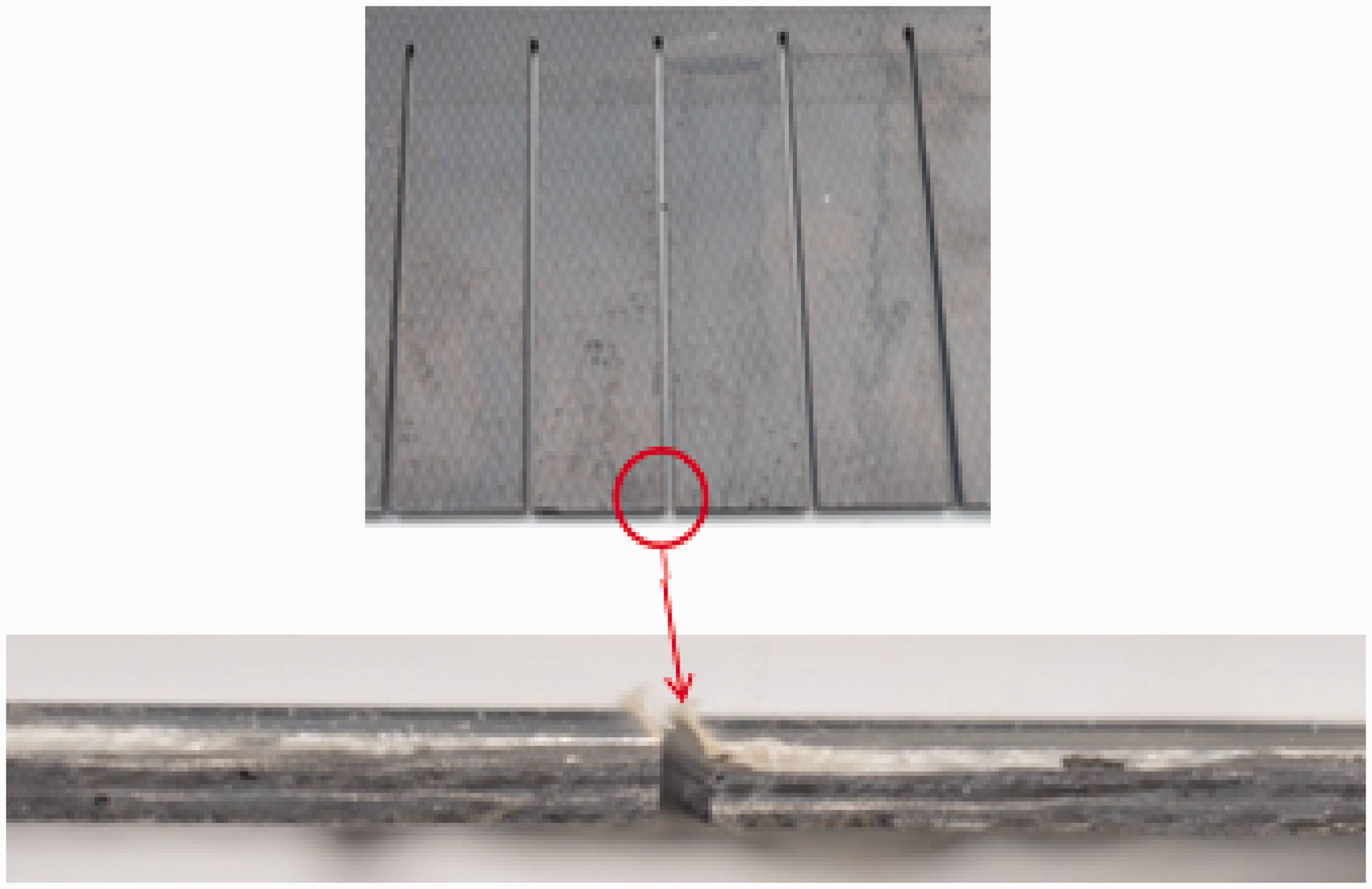
Surface roughness was measured by taking samples consisting of the kerf wall. A portable roughness testing machine produced by Mitutoyo was used to measure the Ra value. It is of compact display type and the model number is SJ 201 as shown in Figure 3.
Portable surface roughness tester.
Kerf width at top and bottom was measured. The Kerf taper angle T can be calculated from kerf width values as illustrated in Figure 4 by using the following equation
AWJ cut profile. AWJ: abrasive water jet.

Figure 4 denotes the cut profile of an AWJ machined workpiece. A through cut made on the material by AWJ is shown where in the top kerf width is larger than the bottom kerf width resulting in kerf taper. This taper should be minimized as much as possible to achieve superior cut quality.
Results and discussion
Design layout with responses.

Effect of AWJ cutting parameters on surface roughness
ANOVA table for surface roughness (Ra).

ANOVA: analysis of variance; SOD: standoff distance; TR: traverse rate.
Figure 5(a) and (b) shows the effect of the SOD and TR on the surface roughness for 5 mm thick laminates. The result indicates that for a laminate of fixed thickness, when SOD and TR increase, the surface roughness would be increased. When we increase the TR, only very less overlap cutting action takes place and very few abrasive particles strike the surface. Also, a faster traverse results in increment of jet deflection. Hence, it results in very high Ra values. So, a lower TR is required to get a good surface finish on the cut kerf.
(a) Three-dimensional plot and (b) contour diagram showing the responses of SOD and TR on surface roughness for 5 mm thick laminates. SOD: standoff distance; TR: traverse rate.
The interaction effects of SOD and thickness on surface roughness are represented in Figure 6(a) and (b) for a TR of 250 mm/min. It can be seen from both Figures 5 and 6 that the surface roughness is a function of SOD. Higher SOD results in divergence of the jet before it strikes the surface. This leads to external drag from the environment that prevails during the process. Jet diameter is thus increased as the cutting process is initiated. This in turn results in the reduction of kinetic energy density due to high interaction volume. Higher kinetic energy is preferable to get a good penetration capability [15] so that the jet can cut through the material easily providing a smoother surface. So, it is preferable to have a lower SOD.
(a) Three-dimensional plot and (b) contour diagram showing the responses of SOD and thickness on surface roughness for 250 mm/min TR. SOD: standoff distance; TR: traverse rate.
From Figure 7, the surface roughness values observed are low in the low thickness laminates compared with the high thickness laminates. This is due to high penetration depth and more energy loss, leading to more erosive wear rather than sharp cutting at the exit side of the jet, generating a spiky, rougher surface. From the analysis, it has been found that above all the parameters, TR is found to have the greatest influence on the surface finish and it is in agreement with the experiments done by Alberdi et al. [16].
(a) Three-dimensional plot and (b) contour diagram showing the responses of traverse rate and thickness on surface roughness for 0.5 mm SOD. SOD: standoff distance.
From Figures 6 and 7, we also observe that the surface roughness is high when t = 5 mm while it is comparatively low in the other two laminates. This is because of the fiber orientation in the various plies of the laminate. Sharp and clean cuts can be obtained in the case of 90° orientation than 0°. This is because of the larger resistance offered by the 0° ply due to a larger shear area. As seen from the stacking sequence of these symmetric laminates, about the midplane, the jet encounters the 0° ply more in the case of the medium thickness laminate resulting in rougher cuts.
Based on the experiment results, a mathematical model was devised to correlate the input parameters and the response. RSM technique has been applied for developing the mathematical relationships between the factors (dependent variable) and responses (independent variable) for determining desired factors, which yield optimum cutting quality.
Regression equation for surface roughness

SOD = standoff distance
TR = traverse rate
t = thickness
The regression equation represents the relationship of the interaction and quadratic terms with the response Ra and this equation will be useful to find the optimum cutting parameters for better cut quality using numerical optimization technique available in the design expert software.
Effect of AWJ cutting parameters on kerf taper angle
ANOVA table for kerf taper angle.

ANOVA: analysis of variance; SOD: standoff distance; TR: traverse rate.
There is just a little possibility (0.15%) that “Model F-Value” of this magnitude could have got generated due to noise. Values of “Prob > F” less than 0.05 point out that the model terms are significant. In this case the SOD, TR, thickness (t), and the quadratic effect of thickness (t2) are the significant model terms associated with kerf taper angle. Those which are higher than 0.1 imply that the model terms are not significant. The “Lack of Fit F-value” of 214.9 indicates there is a 5.01% possibility that a “Lack of Fit F-value” this high magnitude could occur due to noise.
Figures 8 and 9 give the 3D surface and contour plots of responses due to interaction of various process parameters on the kerf taper angle. Figure 8 shows that kerf taper is low at low SOD and low TR for 5 mm thick laminates. When SOD is increased, the AWJ expands before impinging the surface and hence the density of the abrasive particles is reduced. Eventually, the penetration depth is reduced resulting in large variation of kerf widths on the top and bottom surface.
(a) Three-dimensional plot and (b) contour diagram showing the responses of SOD and TR on kerf taper for 5 mm thick laminates. SOD: standoff distance; TR: traverse rate. Three-dimensional plot and contour diagram showing the responses of SOD and thickness on kerf taper at TR = 250 mm/min. SOD: standoff distance; TR: traverse rate.

Figure 9 shows that at low SOD and medium thickness range, kerf taper is low for the TR of 250 mm/min. For low SOD the kinetic energy of AWJ beam increases and which results in sharp cutting to reduce the kerf taper. When SOD is increased, surface of the laminate gets exposed to the downstream of the AWJ. Here, the jet begins to diverge. This results in reduction of cutting area. The result shows that SOD has more influence on the kerf characteristics.
As TR is increased, the faster passage of the AWJ permits only lesser number of particles to impinge the laminate and this decreases the kerf width [17]. Bottom kerf width decreases more rapidly than that of the top. Thickness parameter and its interaction with TR is also analyzed and the behavior is seen in the contour and surface plots (refer Figure 10). The result confirms that decreasing the TR will much reduce kerf taper angle due to more exposure time for cutting, leading to more overlapping of the jet on the target material.
(a) Three-dimensional surface plot and (b) contour diagram showing the responses of thickness and TR on kerf taper for 5 mm SOD. SOD: standoff distance; TR: traverse rate.
Also, from Figures 9 and 10, we observe that kerf taper angle is low in the case of the laminate with medium thickness. This is because of the lesser volume fraction encountered during the cutting of 0° ply than that of the other orientations. About the plane of the symmetric laminate, when 0° ply is encountered more as in the case of the laminate with medium thickness, variation of kerf width is reduced resulting in less kerf taper.
Regression equation for kerf taper angle

Figure 11 shows how the actual and predicted values of Ra and kerf taper vary. We observe that the developed model is adequate [18] and predicted values agree with the data obtained from experiments.
Plots of actual versus predicted values (a) Ra and (b) kerf taper.
On each contour plot, the undesirable areas were grayed out to construct the overlay plot. The colored (yellow) area that remains defines the final optimal factor settings. Figure 12 shows the plot and the optimum cutting conditions.
Overlay plot showing the best possible cutting condition for 3 mm thickness.
SEM analysis
SEM images were obtained from the cut zone of the samples and are presented in Figures 13 and 14. Examination of the cut surface through SEM revealed that fiber fracture resulted from the micro cutting and erosion by abrasive particles.
Fracture topography observed in the SEM image of the cut zone of sample with thickness 3 mm and fiber orientation angles of 0° and 90°. SEM: scanning electron microscope. Fracture topography observed in the SEM image of the cut zone of sample with thickness 5 mm and fiber orientation angles of 0° and 90°. SEM: scanning electron microscope.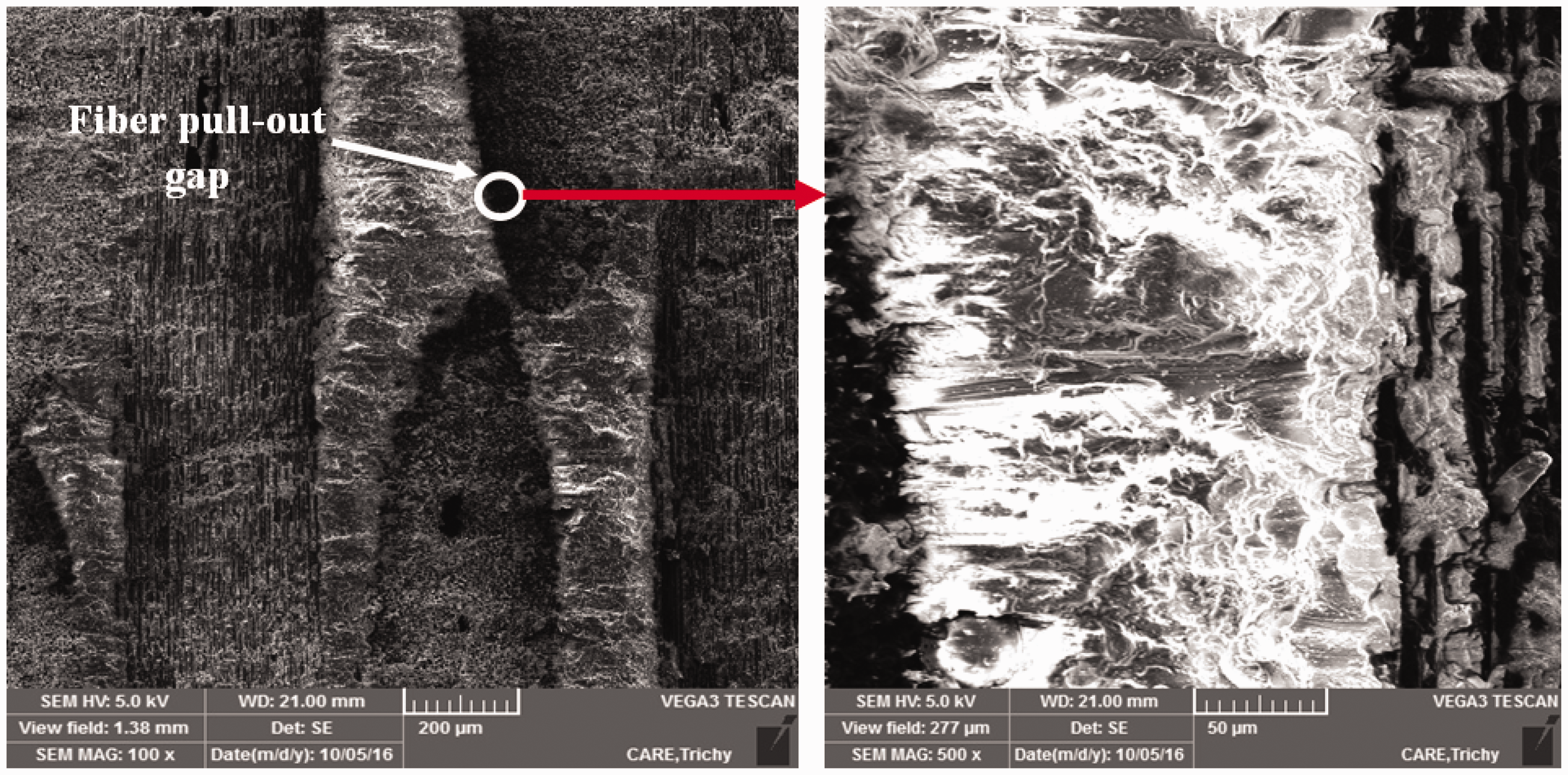

The fracture zone mainly consists of epoxy matrix with some fractured carbon fibers (refer Figure 13). Furthermore, material inner fractures are found to be generated at certain spots where fiber is susceptible to bending and breaking. This resulted in gaps of carbon fiber at the surface.
From the fracture topography, it is concluded that the cracks were generated because of the debonding of fiber–epoxy interface. This led to the loss of support from the epoxy polymer for the fibers. Then, cracks propagated in the direction of fibers, which eventually led to the breakage of epoxy phase into small fragments and separation of fiber inside the laminate. The formation of delamination started with the generation of internal cracks with the initial impact of the AWJ on the material. This is because the material was not able to withstand the shock wave [13].
From the SEM images, we also observe that the cutting of matrix phase consists of shearing and ploughing in the upper region. Intergranular cracking was observed in the lower region. This is in accordance with the findings of Wang [19]. From Figure 14, we observe that the fiber distribution is homogeneous. This is in agreement with the findings of Kuzu [20].
Numerical optimization
Constraints for optimization.

SOD: standoff distance.
Solutions of the numerical optimization.

SOD: standoff distance.
Validation
Validation results.
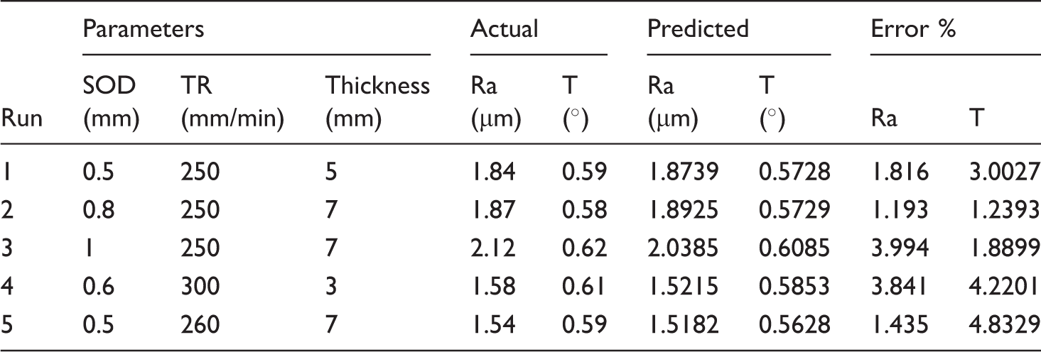
SOD: standoff distance; TR: traverse rate.
Conclusion
This work has discussed the cutting of carbon fiber reinforced plastic composites through AWJ machining process. Based on the experimental results and statistical analysis, SOD is the dominating factor for the minimization of kerf taper angle and surface roughness followed by TR. The main conclusions obtained from this work are as follows:
SOD and TR are the prime factors affecting the Ra value and the taper of cut kerf. Higher SOD results in large kerf taper angle due to exposure of the material surface to the downstream of the jet. At downstream, the jet starts to diverge losing its coherence thereby reducing the effective cutting area that directly affects the kerf taper angle. Increasing the TR increases surface roughness and taper angle of the kerf too. Hence lower TRs are preferable when cut quality is of high importance. During the cutting process with the fiber orientation of 0° and 90°, the main defects observed in the fiber are pullout and damage in the surface level. The optimum process parameters that provide the best cut quality are identified. It is recommended that a combination of low TR and short SOD is suitable to produce more vertical kerf wall in AWJ cutting. The predicted values of surface roughness and kerf taper obtained by using the mathematical model are in good agreement with the experimental values within 5% of absolute error.
Analysis can further be done with the help of finite element techniques on the mechanism of deformation in the interlaminar region of the composite material during the cutting process.
Footnotes
Declaration of Conflicting Interests
The author(s) declared no potential conflicts of interest with respect to the research, authorship, and/or publication of this article.
Funding
The author(s) received no financial support for the research, authorship, and/or publication of this article.