
Abstract
This paper undertakes to study the flexural behavior of 3D integrated weft-knitted spacer composites, under three-point bending. The integrated-knitted spacer fabrics were produced with various cross-sectional shapes on a computerized flat-knitting machine utilizing electrical grade glass (E-glass) fibers. The sandwich composites were manufactured by vacuum-assisted resin transfer molding using unsaturated polyester resin. Continuing the process, hand lay-up method was used to reinforce the face sheets of fabricated sandwich structure with glass woven fabrics. Bending performance of the produced composites was compared with polyurethane foam core sandwich composites. The results revealed that the cross-sectional shape has significant effect on the bending performance of the 3D integrated weft-knitted spacer composites. Also, the spacer reinforced composite with V-shape cross-section has the highest bending stiffness than composites with U-shape cross-section as well as polyurethane foam core sandwich composite. The failure modes of 3D integrated weft-knitted spacer composites include: core shear failure, compression failure of upper face sheet and tensile failure of lower face sheet.
Introduction
Sandwich structures have found extensive applications in different fields such as aircraft, missile and spacecraft structures due to their high specific strength. Composite sandwich materials are produced by attaching two thin, strong and stiff skins to a lightweight thick core. The upper and lower skins are commonly made of composite laminates and metals, while the core usually consists of metallic and non-metallic honeycombs or cellular foams [1,2]. The core materials normally possess low strength, but its higher thickness provides high bending stiffness and low density for the whole composite structure. Under the applied external loadings, the face skins usually tolerate the tensile, compressive, and shear stresses, while the core withstands the shear stresses.
Many researchers have studied bending and shearing behaviors of sandwich structures. Othman and Barton [3] investigated the failure initiation and propagation characteristics of honeycomb sandwich composites subjected to quasi-static and impact loadings. Load-carrying, energy-absorbing characteristics and failure mechanisms under quasi-static and impact loading were determined. The results demonstrated that failure modes involved upper skin compression failure in the vicinity of the indenter, core crushing and lower skin tensile failure. Lua et al. [4] prepared a kind of composite honeycomb using carbon fiber and epoxy resin by the help of compression molding technique. Mechanical performance of the composite honeycomb sandwich in term of three-point bending was characterized using finite element analysis. Results indicated that the failure mode is interfacial de-bonding between honeycomb core and face layers. Russell et al. [5] manufactured honeycomb structures from carbon fiber composite sheets. Analytical expressions were derived for four competing collapse mechanisms (core shear, face microbuckling, face wrinkling, and indentation) of simply supported and clamped sandwich beams in three-point bending. The results showed that the presented finite element (FE) model is able to predict the measured load versus displacement response and the failure sequence in each of the composite beams.
Many researchers [6–10] have investigated the relationship between the failure mechanisms, type of material used and the geometrical configuration of sandwich structures during bending test. Steeves and Fleck [11] devised a systematic procedure for comparing the performance of sandwich beams made of various materials combinations. They identified the operative failure mechanisms and optimized the geometry of the sandwich structures to reduce the structural weight for a given load-bearing capacity. Petras and Sutcliffe [12] studied the failure mechanisms for glass fiber-reinforced plastic (GFRP) skins/honeycomb core sandwich beams. They then prepared a failure mode map showing the affectability of failure mode and load by the ratio of skin thickness to span length as well as honeycomb density. Mamalis et al. [6] investigated the flexural properties, collapse modes and crushing characteristics of various types of composite sandwich panels during three-point bending test. Two modes of collapse including the shear failure of foam core and the local indentation collapse mode were reported. Gdoutos and Daniel [7] studied the failure modes of foam-core sandwich beams. The face sheet and core materials were fully mechanical characterized. Different failure modes were individually studied for these structures and both initiation and ultimate failure were determined. Valenza et al. [8] analyzed the failure mechanisms of GFRP/PVC (poly vinyl chloride) foam core sandwich structures subjected to three-point bending. By varying the skin thickness and the span length between supports, experimental tests were carried out in order to find the relationship between the geometrical configuration of the sandwiches and the failure mechanism.
When the sandwich structures are subjected to bending and shear forces, disbondments would be initiated and propagated between the structural connection points which resulted in reducing the load-carrying capacity of structures. One solution to solve this problem is using the sandwich composites reinforced with three-dimensional fabrics.
3D spacer fabrics are developed with different techniques such as weaving, warp knitting and weft knitting. Conventional spacer fabrics include two surface layers which are connected through pile yarns. Higher strength of the reinforced composites against any external loading could be achieved when the two outer layers are connected together through woven or knitted crosslinks instead of pile yarns. These 3D spacer fabrics normally have excellent performance characteristics due to their unique structure, such as high impact resistance, heat resistance and sound absorption; therefore, these technical textiles have found applications in various fields, such as protective clothing, transportation, geo-textiles, buildings, packing materials, military equipment, medicine, sports, etc. Fan et al. [13,14] fabricated different composites reinforced with woven spacer fabrics in order to investigate their failure mechanisms and energy absorption abilities. Brandt et al. [15] reviewed the mechanical performances of various 3D-woven composites by making comparison between their in-plane properties, damage tolerance, energy absorption capability and fracture mechanism. Vuure et al. [16,17] studied the strength and stiffness of 3D-woven composites using experiments analyses and numerical simulations.
In recent years, flat-knitted 3D spacer fabrics due to high potential to create the complex cross-sectional shape, high energy absorption capacity and low production costs have become attractive for making composite structures. Surface layers of flat-knitted 3D spacer fabrics can be connected by knitted crosslink. These structures are characterized by a various cross-sectional shapes and dimensions depend on the number and orientation angle of knitted crosslinks. The shape of the connecting layer or knitted crosslink can be different, varying from rectangular to elliptic, V shaped, trapeze, etc. [18]. Among various researchers focusing on manufacturing 3D spacer knitted preforms, Abounaim et al [18–20] is a pioneer who succeed to fabricate thermoplastic composites reinforced with flat-knitted 3D spacer fabrics. Hassanzadeh et al. [21–23] investigated the mechanical properties of thermoset composites reinforced by spacer weft-knitted fabrics. They produced 3D spacer knitted fabrics with four different cross-sections which were infused by epoxy resin through the vacuum infusion molding process. Their results showed that the produced panels have higher compression resistance than the conventional woven and warp-knitted spacer composites. Hamedi et al. [24] explored the multi-scaled simulation of flexural properties of 3D weft-knitted spacer fabric-reinforced composites under three-point bending. The spacer knitted composite containing U-shape cross-section cross-link was fabricated using high-tenacity polyester yarns and epoxy resin. A good conformity was reported between experimental and simulating results. Despite the high potential of this type of knitted composites to use in technical applications, limited studies have been carried out in this area.
This study aims to investigate the effect of cross-sectional shape of the connecting layers on bending behavior of the 3D integrated weft-knitted spacer composites. Different 3D spacer fabrics (3DIW-KSC) with varied geometry in cross-section will be produced on a computerized flat knitting machine. Using the prepared fabrics, the composite parts would be manufactured through VARTM method with unsaturated polyester resin. The analyses of failure mechanisms of 3DIW-KSC as a result of three point-bending test are going to be performed. Bending performance of the produced composites will be compared with PU foam core sandwich composites.
Experiments
Production of integrated 3D spacer weft-knitted fabrics
3D spacer weft-knitted fabrics with different structures as well as cross-sectional shapes as schematically depicted in Figure 1 were fabricated on a computerized flat knitting machine (Stoll CMS-400, E5), using 2/100Tex E-glass yarns. Glass fibers generally suffer from low bending strength which leads to fiber damage in contact with knitting elements while converted into a looped-shape configuration. To avoid the glass fiber breakage during knitting process, precise setting of the production variables such as loop length as well as fabric tension is necessary. Tensile properties of single-ply yarns regarding their tensile strength and stiffness were carried out according to ASTM D2256 standard test method from which the results are given in Table 1.
3D spacer weft-knitted fabrics with different cross sectional shapes; (a) single-decker U-shape, (b) single decker V-shape, (c) double-decker U-shape. Yarns characteristics used for knitting process.
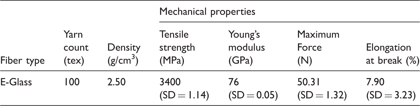
Figure 2 typically depicts main steps of fabricating single-decker U-shape spacer fabric on a flat knitting machine. During first step, the two outer layers with a predetermined length are knitted only by odd needles of both needle beds. In the next step, the junction of connecting layer with one of the outer layers is created. In the third step, the connecting layer is knitted on even needles of the front needle bed. The length of the connecting layer can be varied according to the required thickness for the final product. Prior to the loop transferring, racking technique is caused so that the odd needles of rear bed face the even needles of front bed. Using loop transfer technique, the connecting layer could be conjugated between the two outer layers. Repeating this sequence leads to produce the 3D-knitted spacer fabric as depicted in Figure 1(a).
Knitting steps of single-decker U-shape spacer fabric on a flat knitting machine.
Stitch density of the surface and connecting layers can significantly affect the mechanical performance of the resultant composite. Mean value measured for stitch density of the knitted layers was 9 stitches per cm2. This parameter was kept constant for all knitted spacer fabrics with different structures and cross-section shapes.
Composite manufacturing
Before composite manufacturing from the produced 3D-knitted spacer fabrics, auxiliary components such as wooden rods were employed in order to fill the fabrics’ structural cells, so that the whole structural geometries could be kept unchangeable during molding. This operation is essentially required since the fabrics are so flexible and would change their geometrical shape, once they are pressed through the vacuum procedure. For this aim, wooden inserts with similar dimension as the individual fabric samples were designated [21]. Wooden rods could be simply separated from the molded composites if they were coated by silicon tapes and releasing agent (wax). Figure 3 shows the prepared 3D spacer fabrics of different cross-sectional shapes to be molded and converted into 3D composite parts.
Sample preparation before molding (a) single-decker U-shape (b) single-decker U-shape with double height value (c) single-decker V-shape (d) double-decker U-shape.
Unsaturated polyester thermoset resin was used to fabricate the composite samples. Figure 4 demonstrates the various steps of the composites molding. The method of resin transferring based on vacuum infusion principles was carried out using a vacuum pump capable of providing a maximum negative pressure of 1 bar. Once the full resin impregnation was completed, the vacuum pressure was removed and the resin-impregnated fabric samples were allowed to be conditioned at room temperature for 24 h. For improving their mechanical properties, the samples were then post-cured in an oven for 2 h at 120℃. The cured composite samples are illustrated in Figure 5. To enhance the bending rigidity of the surface layers of the fabricated composites, woven glass fabrics characterized in Table 2 were attached to composite samples using unsaturated polyester resin via hand-layup method. This process is depicted in Figure 6.
Steps of VARTM processing of 3DIW-KSC. The 3DIW-KSC samples produced by VARTM. Woven fabric characteristics. Hand layup steps for reinforcing of face sheets.


Specifications of knitted composites and PU foam core sandwich samples.

PU: polyurethane; DD: double decker.
As it is widely known, the fiber volume fraction of textile reinforced composites plays an important role in their mechanical performances. For this reason, measuring the fiber volume fractions (Vf) of the produced 3D composite samples was determined using burning-off technique in which the reinforcing glass fibers could be remained after the whole removal of polyester resin and then measured as the samples Vf. Then the fiber volume fractions were determined using equation (1). This given values of Vf for each sample are determined by averaging between five measurements. The fiber volume fraction of knitted and woven sheets was separately measured as 23% and 36%, respectively.

Three-point bending test
Thermoset glass/polyester composite samples reinforced with integrated 3D spacer weft-knitted fabrics were tested under three-point bending loads according to ASTM C 393 standard methods. This study was performed in order to find the bending behavior and failure mechanism of samples in relation with their geometrical characterizations. Three specimens with dimensions based on ASTM C 393 standard were prepared and then were tested using a universal tensile tester with the capacity of applying maximum force of 15 ton. The span length and test speed were considered as 80 mm and 5 mm/min, respectively. All the mechanical tests were performed at room standard condition (20 ± 2℃ temperature and 60 ± 5% relative humidity). The same setting was considered for the bending test of the produced PU foam core sandwich composites. The results of these tests could be helpful to compare the bending performance of the 3D spacer knitted composite against the PU foam core sandwich composites. Figure 7 illustrates the three-point bending test setup.
Three-point bending test setup.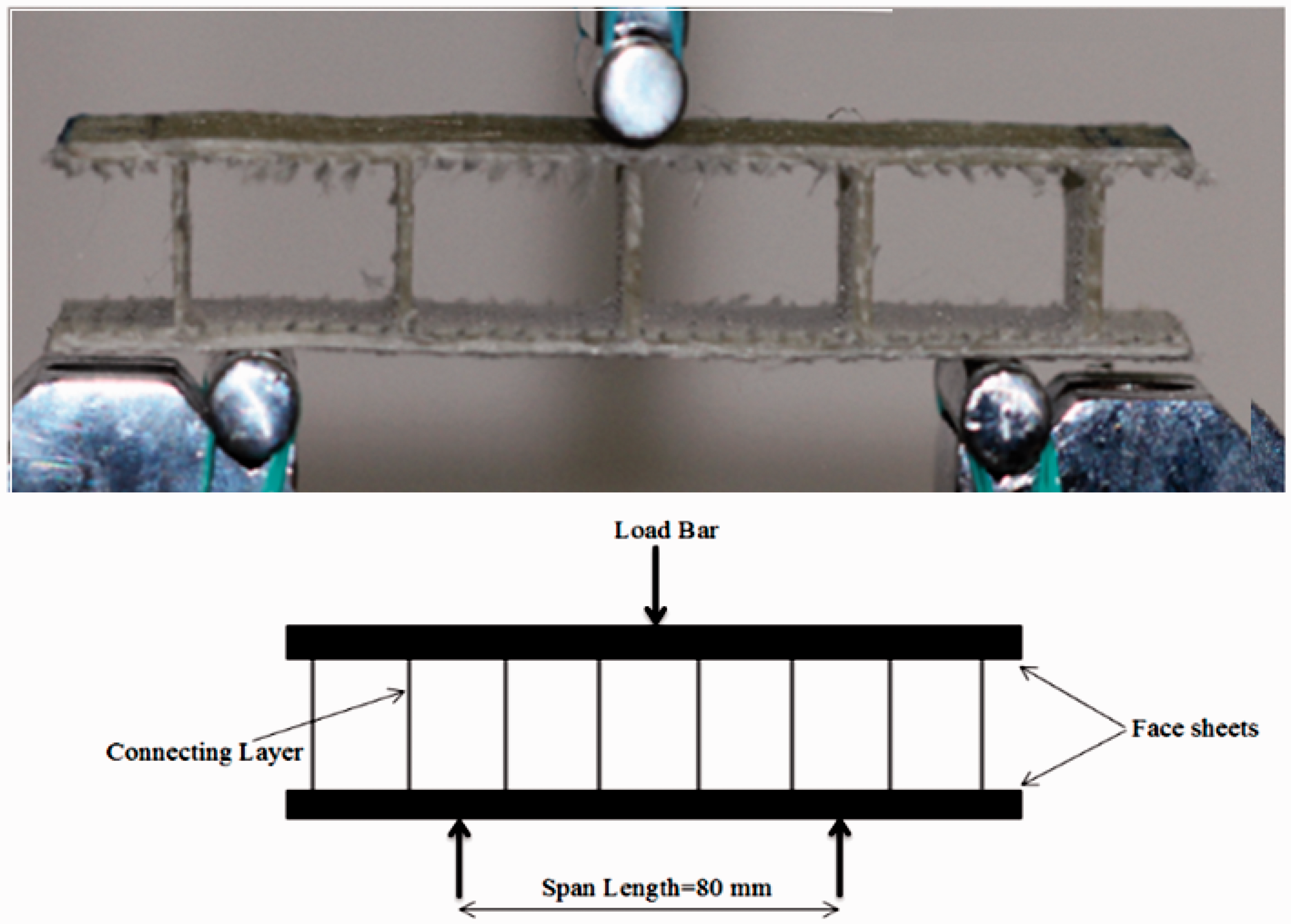
Results and discussions
Statistical analysis of three-point bending test


Statistical descriptive values of 3DIW-KSC extracted from three-point bending test.
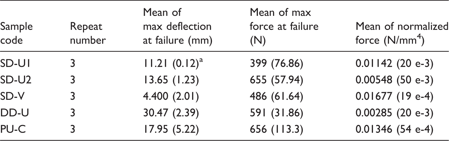
The values in parentheses are standard deviation.
3DIW-KSC: 3D integrated weft-knitted spacer composites.
The results demonstrate that single decker V-shape composite (sample SD-V) has the least and PU foam core sandwich composites (sample PU-C) and double decker U-shape composite (sample DD-U) have highest bending deflection at failure. The spacer knitted composite with triangular cross-section shape (sample SD-V) demonstrates the highest maximum bending force in comparison to other composites and foamed core sandwich composite (sample PU-C).
In addition, knitted spacer composite with double-decker U-shape cross section (sample DD-U) has the lowest maximum bending force. An increase in thickness of the single decker U-shape composite causes to increase the maximum force at failure of structure under three-point bending loading. In overall, the single decker U-shape composites (samples SD-U1 and SD-U2) do not represent satisfactory bending results compared with foamed core sandwich composite (sample PU-C).
Analysis of variance of sandwich composites under three-point bending.

Note: +: significant difference between groups, −: not significant difference between groups. ANOVA: analysis of variance.
Failure mechanism of 3DIWKCSC under three-point bending
This section describes experimentally failure mechanisms of 3DIW-KSC and PU foam core sandwich composite subjected to three-point bending.
Composites with single-decker U-shape
Due to similar composite cross-sectional shape for samples SD-U1 and SD-U2, only the failure mechanisms of sample SD-U2 is analyzed. Figure 8 shows the deformation steps of composite sample SD-U2 during three-point bending tests. In addition, force–deflection curves of sample SD-U1 and SD-U2 under three-point bending are depicted in Figures 9 and 10.
The stage of experimental failure mechanism of sample SD-U2 under three-point bending. Force–deflection curves of composite sample SD-U1 extracted from three-point bending test. Force–deflection curves of composite sample SD-U2 extracted from three-point bending test.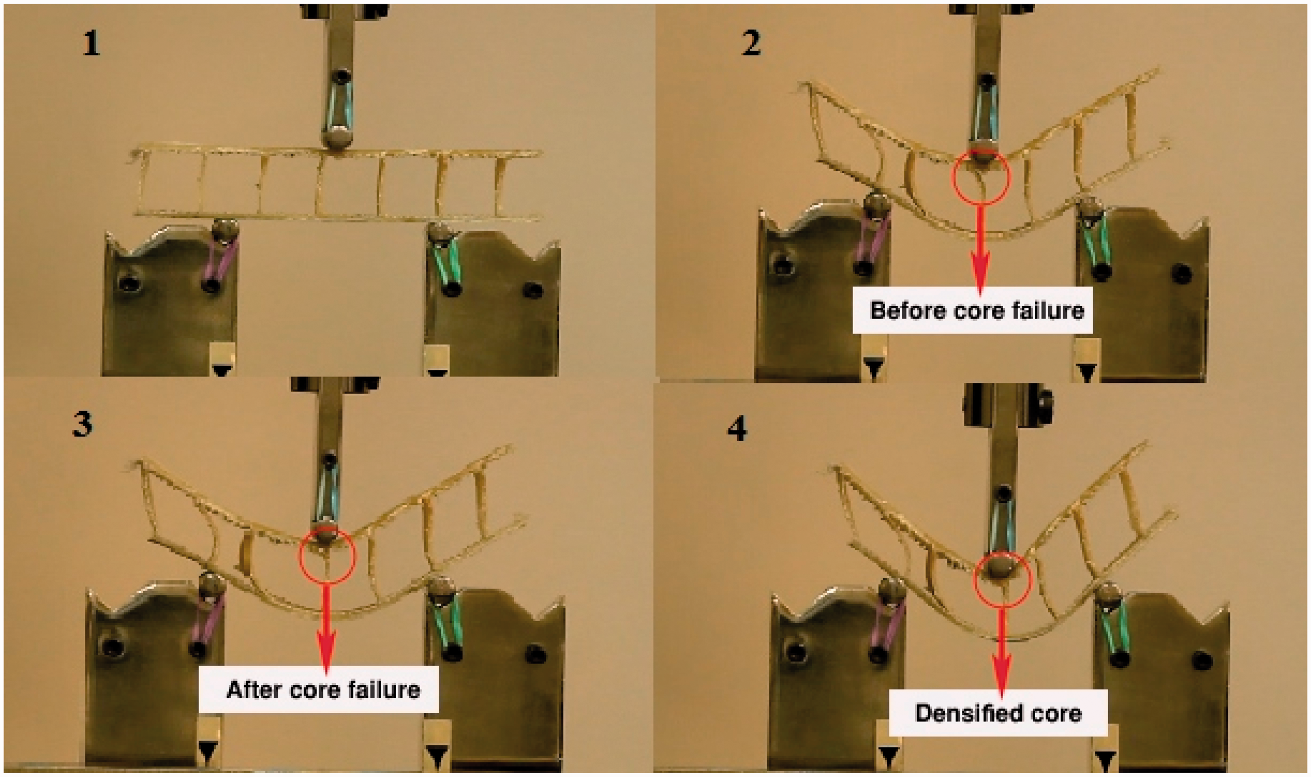


A close look at the extracted force-deflection curves (Figures 9 and 10) reveals four different deformation stages. In the first stage, slope of the curves increases linearly, as the sample DD-U deflection increases. In this stage, no structural damages could be observed and removing the applied force would be resulted in complete sample recovery and maintenance of its primarily properties. In the second stage of loading, the buckling failure would have happened in addition to several cracks that could have occurred within the matrix. This failure mode leads to the reduction of samples structural properties. According to Figure 9, upon the third stage of deflection, further increasing in the applied deformation leads to catastrophic failure formation in the core which is followed by a sudden drop of the force–deflection curves. By continuing the applied deflection, as depicted in the stage 4 of Figure 9, densified core is occurred and the slope of the curves is increased slightly.
Single decker V-shape-knitted composite
Figure 11 shows the deformation stages of single decker V-shape-knitted composite (sample SD-V) during three-point bending test. As it can be seen in Figure 12, the force–deflection curve of this composite sample in the primary stage can be divided into two different parts: the first part is related to the linear elastic behavior of samples (up to 250 N), while the second indicates nonlinear elastic behavior of the loaded samples. In this area, no significantly visible damages could be observed in the matrix phase. In the second stage in Figure 12, further deflection leads to core buckling occurrence and formation of some cracks within the matrix phase. Accordingly, the curve slope decreases which could be due to decreased the mechanical properties of the composite structure. In stage 3, more increment in the samples deflection would be resulted in core failure followed by such intense loss in the force–deflection curves’ slopes. Finally, in stage 4, larger deformation leads to densified core phenomenon in which the slope of the curves increases slightly, followed by the failure of the face sheet.
Deformation stages as well as failure mechanism of sample SD-V under three-point bending. Force–deflection curves of samples SD-V extracted from three-point bending test.

Actually, the bending force applied to sandwich composite structure during three-point bending process is combination of axial and shear loading as well as bending moment. Core part in sandwich structures provides the required resistance against the applied shearing forces. Therefore, the least bending deflection at failure as well as highest maximum bending force in single decker V-shape composites is attributed to high potential of V-shape geometrical structures to resist against shear loadings.
Double decker U-shape composite
Progressive damage failure of double decker U-shaped composite (sample DD-U) under three point bending, as well as it corresponding force-deflection curves are shown in Figures 13 and 14, respectively. In the first stage of deflection, the slope of the force-deflection curves increases smoothly. Initial smooth slope of the resultant curve could be due to overlap of connecting layer to each other and large deformation of the thin middle layer of composite sample by applying a small amount of force. In second stage with complete deformation of thin middle layer, the force–deflection curves are increased with a steep slope. In this section, several cracks occurred within the matrix. In third stage, further increasing of deflection causes the core failure which is followed by the sudden drop of the curve. In fourth stage, higher increment of the sample DD-U deflection leads to slightly increasing of the force–displacement curve, which in turn resulted in face-sheet failure.
The stages of progressive failure mechanism of sample DD-U under three-point bending. Force–deflection curves of sample DD-U extracted from three-point bending test.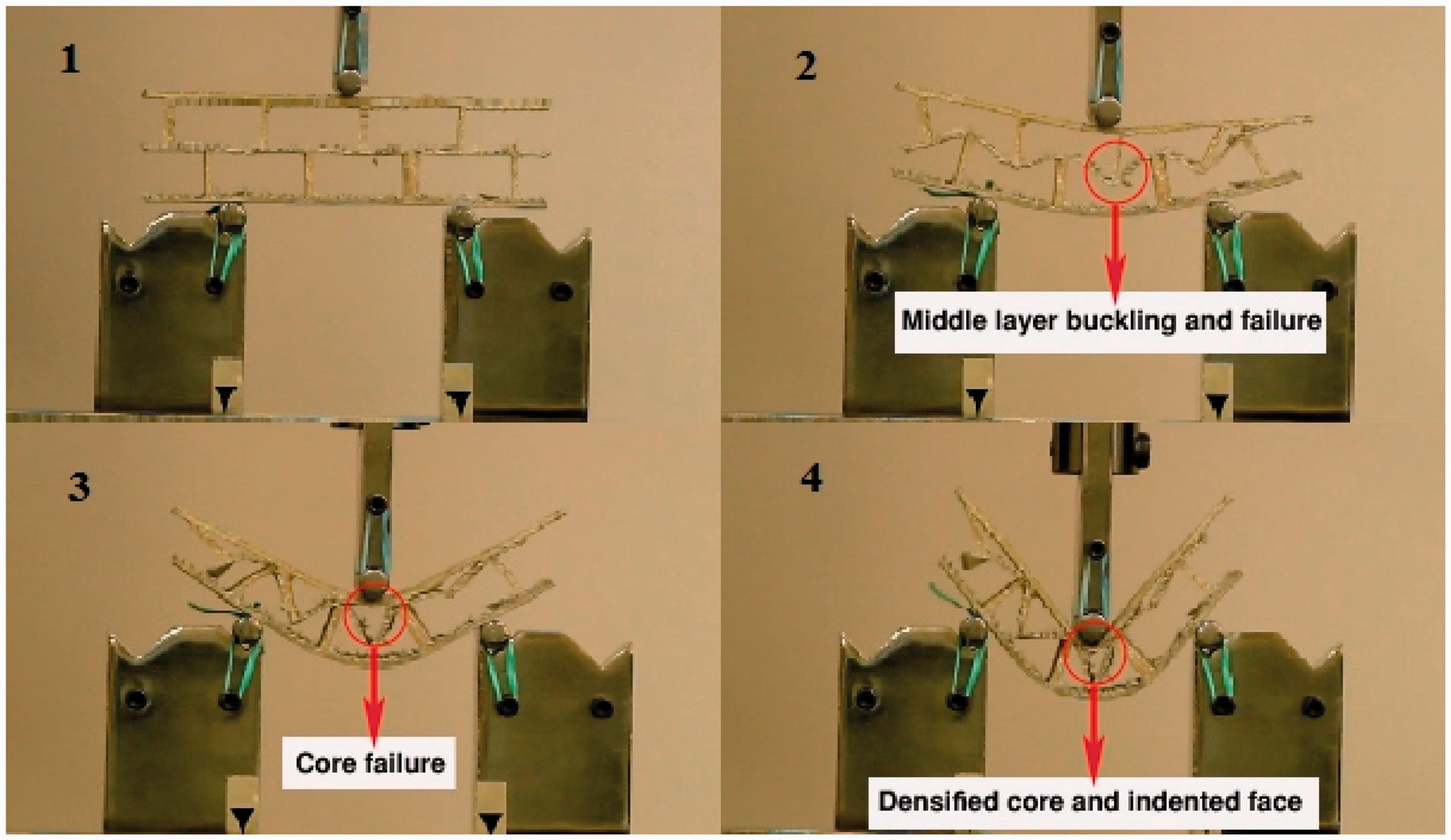

PU-foamed core sandwich composite
Progressive damage failure of sandwich composites with polyurethane foam core and its force–displacement curve are shown in Figures 15 and 16. In the first stage, the trend of force-deflection curves shows the linear elastic behavior of the sample. In the second stage, the slope of the curves grows nonlinearly which suggests the beginning of permanent deformation for the composite samples. In the third stage, further increasing of bending deflection leads to foam core shear occurrence and several cracks formation within the matrix which is followed by changes of the force–displacement curve. In the fourth stage, the face sheet was indented.
The stages of progressive failure mechanism of sample PU-C extracted from three-point bending test. Force–deflection curves of samples PU-C extracted from three-point bending test.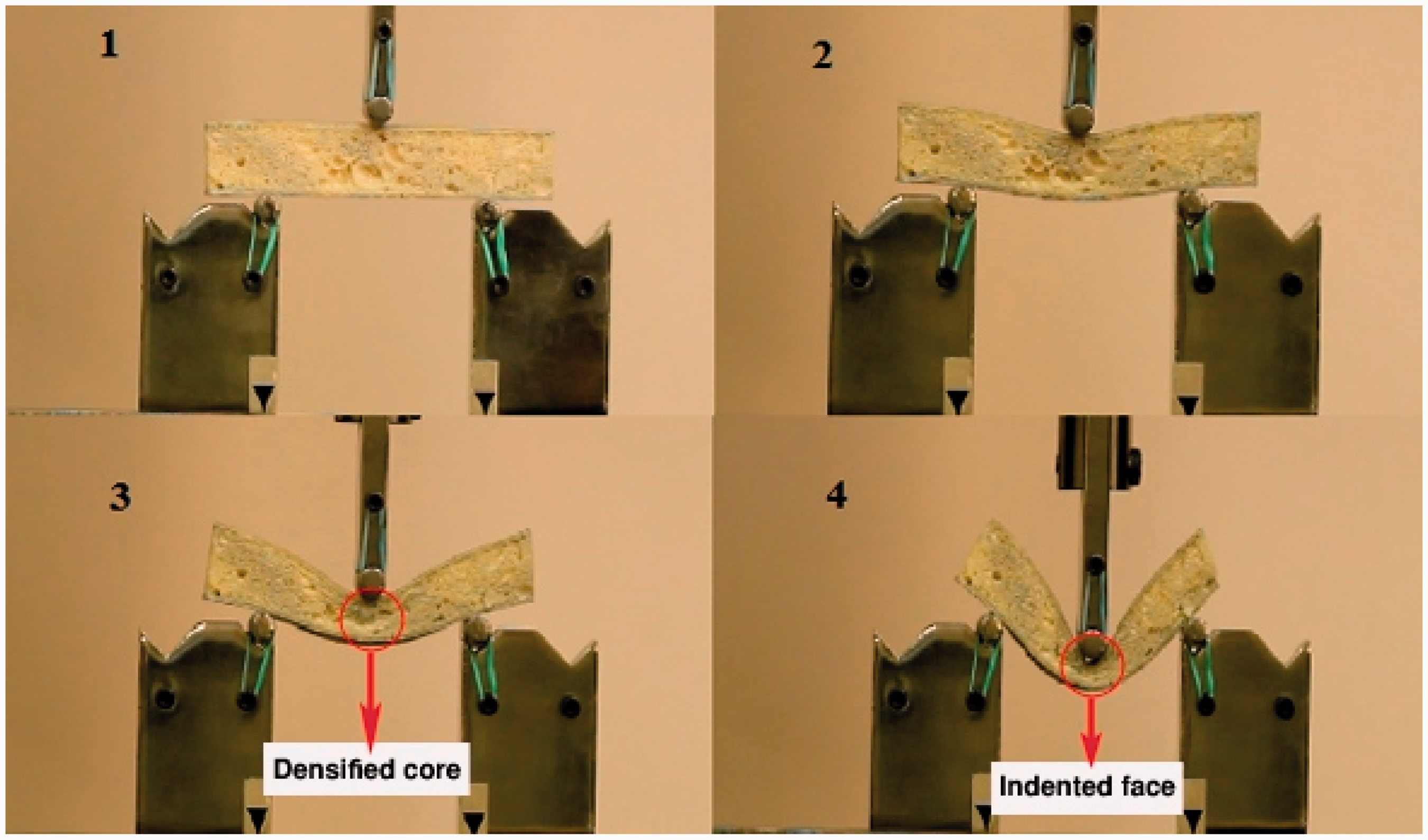

The results extracted from three- point bending test for the newly designed 3D spacer knitted composites revealed no structure delamination. Achievability of 3D configured weft-knitted spacer fabric-reinforced composites with different cross-sectional geometries could provide a wide range of bending stiffness for produced composites. They are recommended to be used for various applications such as marine, aerospace, etc.
Conclusions
The results obtained from the three-point bending test on 3DIW-KSC and PU foam core sandwich composite samples are as follows:
The results of deflection to failure for U-shaped 3D-knitted spacer composites with different total thicknesses showed no significant difference as compared with the sample PU foam core sandwich composite. While the mechanical behavior in terms of flexural strength for double-decker U-shaped 3D-knitted spacer composite was significantly different from the sample PU-C, this could be attributed to the presence of thin middle layer as well as the overlapping effect between the connecting layers. The findings also revealed that V-shaped 3D-knitted spacer composite has the best bending stiffness since it has minimum deflection to failure in comparison with PU foam core sandwich composite. In this regard, the cross-sectional shape was considered as the main effective parameter on 3D spacer composites stiffness. Moreover, it was concluded that 3DIW-KSC samples with triangular cross-section have the highest stiffness than to others. An increase in thickness of the single decker U-shape composites causes to decrease the bending force. In overall, the single decker U-shape composites do not represent satisfactory bending results compared with foamed core sandwich composite. Generally, the failure modes of 3DIW-KSC include: shear failure of core, compression failure of upper face sheet and tensile failure of the lower face sheet. The failure modes for PU foam core sandwich composite include: core shear, compression failure of the upper face sheet and tensile failure of the lower face sheet. No any fractures of delamination type were observed for this newly designed 3D spacer knitted composites (3DIW-KSC) under three-point bending test. Because of achievability of 3D configured weft-knitted spacer fabric-reinforced composites with different cross-sectional geometries, as well as providing high specific strength and stiffness properties, they are recommended to be used for various applications such as marine, aerospace, etc.
Footnotes
Declaration of Conflicting Interests
The author(s) declared no potential conflicts of interest with respect to the research, authorship, and/or publication of this article.
Funding
The author(s) received no financial support for the research, authorship, and/or publication of this article.