
Abstract
In this paper, the mechanical properties of different tetraxial fabrics are investigated. Fabrics were produced using an innovative loom capable of weaving four threads at the same time with complete discretion of yarn type and count. The experimental investigation deals with in-plane and out-of-plane mechanical testing of tetraxial fabrics, as well as yarns made of four different materials (polyethylene terephthalate, glass, aramid, and basalt). The digital image correlation technique was used to measure the in-plane strain field for both uniaxial and biaxial tensile tests. The extensive experimental campaign allowed for a complete mechanical characterization of this novel fabric architecture including interlacement of different yarns.
Introduction
Woven fabrics with special architecture have received considerable attention not only in literature but also in many different industrial applications, due to their mechanical behaviour allowing for peculiar tear resistance as well as improved formability characteristics. With more than two weaving directions, special two-dimensional (2D) and three-dimensional (3D) fabric architectures can be obtained. For example, triaxial braiding produces a 2D architecture with three interlaced yarns; such fabrics have axial yarns in the longitudinal direction and the braided yarns tilted at an angle ranging from ±30° to ±60° with respect to the previous ones. Advantages of triaxial braided fabrics are geometry flexibility and good tear resistance [1]. Increasing the number of weaving direction to four, a 2D multiaxial textile is obtained, which is called tetraxial. It has warp, weft, and two diagonal yarns oriented at symmetrical angles (typically ±45°) with respect to the warp direction. Classification of manufacturing process of technical textile reinforcements for composite materials based on different engineering applications has been summarized in literature [2,3].
A considerable literature is available on the mechanical behaviour of 2D textile reinforcements [4–17]. Moreover, in the last two decades (e.g. Bogdanovich and Mohamed [5], Bilisik [18], and Lima et al. [19]) special attention has been devoted toward improving the in-plane and out-of-plane behaviour of technical textiles.
The enhancement of the mechanical behaviour of technical textiles in multiple directions was investigated in the 1980s by Dow by means of a triaxial fabric [20]. In 1994, tensile performance of tetraxial woven fabric was investigated by Kawano et al. [21], and after that Lima et al. [19] tried to provide specified strengths in multiple directions and improvement of its manufacturing process.
In the present work, a novel special loom [22] was used for manufacturing tetraxial woven fabrics. The fabric architecture combines a traditional orthogonal interlacement with two additional threads (bias), which can be oriented at different angles with respect to the warp/weft direction (Figure 1). In the present investigation, the diagonals are placed at an angle of ±45° with respect to the warp. Moreover, they are continuous and uniformly distributed across the entire width of the fabric. This new tetraxial fabric has different interlacement and geometric features in comparison to those detailed in literature [19, 21].
Micrograph of a tetraxial woven fabric with a sketch of the interlacement in the unit cell.
The additional diagonal threads could be adopted to improve performances in applications where the fabric can be used both on its own and as a reinforcement for a composite material. Moreover, they could also be used to convey new properties or functionalities to the fabric such as, for example, modifying the aesthetic appearance, improving antibacterial capabilities, providing weldability, or allowing signal transmission.
In several applications of these textraxail fabrics, an in-depth knowledge of their mechanical behaviour is required. The mechanical properties of textiles can be predicted using suitable numerical/analytical models. These models allow for a significant reduction of the development and tune-up times with respect to a purely empirical approach; however, experimental validation is required for assessing the accuracy of predictions.
A numerical model to predict the mechanical performance of tetraxial fabrics has been developed and will be validated in a future investigation. The mechanical experimental characterization of hybrid fabrics covered by the present paper is to be considered as preliminary to this goal.
An extensive experimental campaign was conducted on tetraxial fabrics made of different yarns. Tensile, bending, and friction properties of the yarns were determined and uniaxial and biaxial in-plane tensile tests of the fabric were conducted on the fabric. Finally, out-of-plane bending of the fabrics was performed in order to attain complete mechanical performance specifications for this novel architecture.
Tetraxial loom and manufacturing features
The tetraxial loom (Figure 2) combines a traditional woven machine having a vertical beating system (lower part, Figure 3a) with a purposely designed rotating device (upper part, Figure 3b). Diagonal yarns are prepared in the upper part, and an automatic system allows monitoring of the displacement and rotational sequential movements depending on the required areal density of the fabric. When the diagonal yarns enter the lower part of the loom, the rotational movement is converted into a front/back lateral translation, where automatic devices control and monitor the warp density, tension, beating, and weft density. The main advantage of this loom is the total flexibility in selecting the yarn type (material, count, etc.), which can be different in the different directions. This allows for the production of a wide range of fabrics with completely different mechanical behaviour. For further details, the reader is referred to the relevant patent [22].
Some details of the tetraxial loom. Rendering of (a) lower and (b) upper part of the tetraxial loom.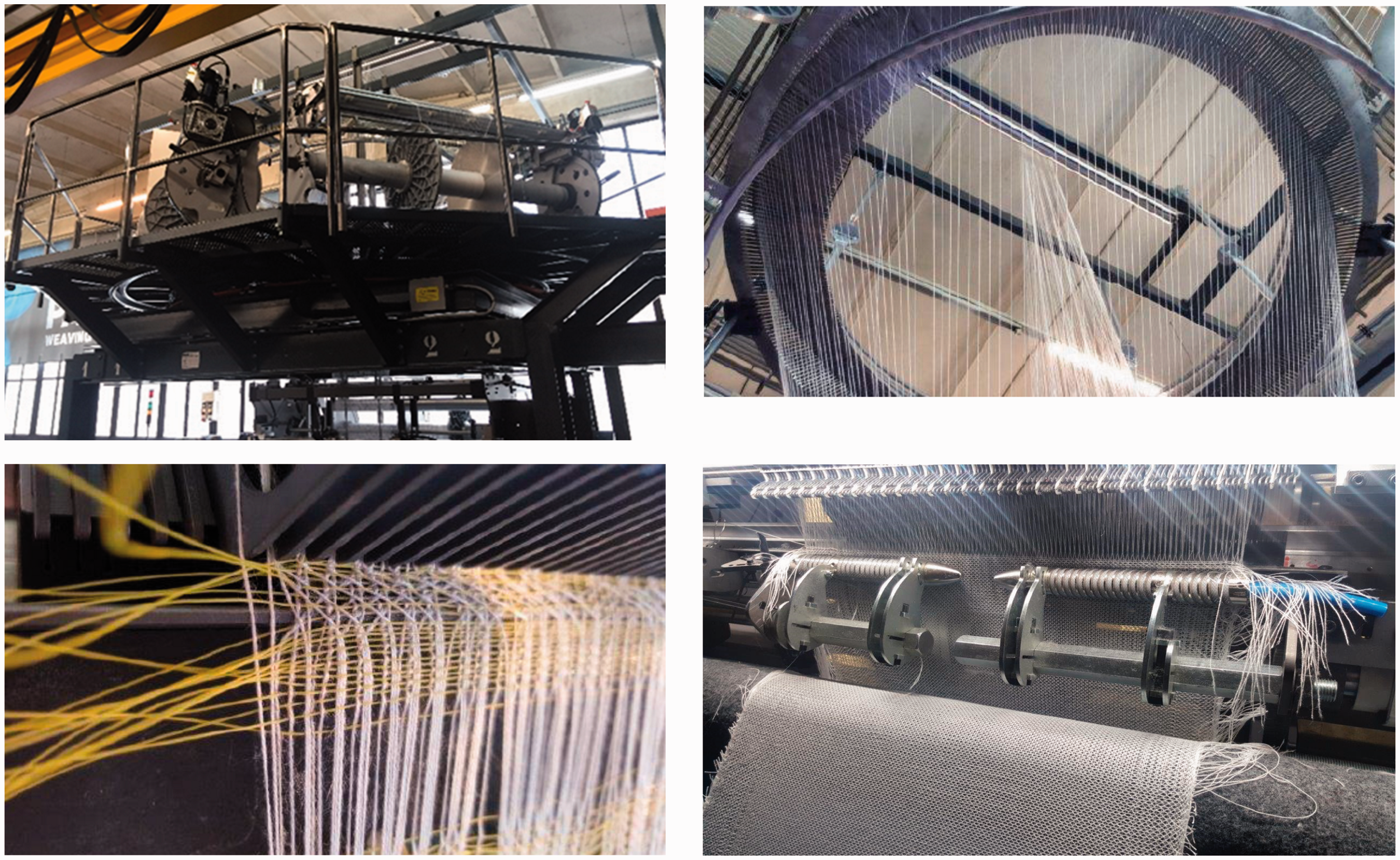

Materials and some geometric features of the tetraxial fabrics
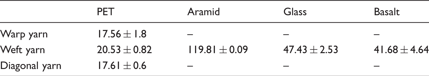
Count and nominal strength of the yarns.

ID and some features of the tetraxial textiles.

Experimental details
The present investigation deals with the in-plane uniaxial and biaxial tensile behaviour and the out-of-plane bending of the tetraxial hybrid textiles. Preliminary tensile, bending, and friction testing was conducted for the four different yarns. The main features of the experimental program, test by test, are detailed in this section.
Uniaxial tensile testing
Yarns
Tensile testing was carried out by an Instron 1121 electromechanical dynamometer (load cell 500 N) on warp, weft, and diagonal yarns extracted from tetraxial fabrics. Glass-reinforced epoxy tabs were applied to the yarns using a 3M DP490 epoxy adhesive (Figure 4) and the assembly was clamped to the dynamometer using a pneumatic system. The testing speed was 5 mm/min. Five replicates were performed for each yarn direction (warp, weft, diagonal).
(a) Picture and (b) scheme of the clamping system of a yarn specimen (‘T’ is tab, ‘R’ is resin, and ‘Y’ is yarn).
Textiles
Tensile tests were conducted in the warp, weft, and diagonal (45°) directions of the tetraxial fabrics using an Instron 1121 electromechanical dynamometer (load cell 5 kN). Glass reinforced epoxy tabs were applied to the specimen using a 3M DP490 epoxy adhesive (Figure 5). The testing speed was 10 mm/min. Three replicates were carried out in each direction for each tetraxial fabric.
Fabric specimen for uniaxial tensile test (tabs thickness 3 mm).
Biaxial tensile testing
A custom-made equipment was used for biaxial tensile testing of fabrics. The loading device is equipped with twelve independent jacks along the two orthogonal axes (Figure 6b). Each jack has a brushless motor with an absolute encoder and a planetary gearbox to transform rotational into linear motion through a ball screw mounted on the axis. The maximum displacement rate is 240 mm/min and the maximum stroke is 512 mm with a displacement accuracy of ±0.05 mm. The load cell for each jack has a maximum capacity of 15 kN.
(a) Fabric cross-shaped specimen dimensions; (b) device for biaxial tensile tests.
The displacement is applied in the two principal directions to a cross-shaped specimen (Figure 6a), which is mounted in the centre of the frame. The loading system allows for an almost uniform biaxial strain filed on the centre part (100 × 100 mm2) of the specimen.
Strain measurement
The strain field in uniaxial and biaxial tensile tests of fabrics was measured using an optical device to continuously record digital images of the specimens during testing. Images were used to obtain a 2D measurement of the full-field displacement and to calculate the strain distribution using a digital image correlation (DIC) technique. DIC procedure consists in comparing speckled surface images of the sample before and after deformation [23] and is widely used to explore full-field displacement and strain in experimental mechanics [24]. In the recent years, DIC technique has demonstrated to be an ideal method in materials science to identify the mechanical behaviour through inverse modelling [25] and to study the deformation characteristics of a wide range of materials ([26–28]).
In this study, the optical device was a Nikon digital camera (resolution of 36 Megapixels) and VIC-2D software was used for 2D image correlation [29]. The main parameters for a proper correlation are the subset size (the area of the image that is used to track the displacement between images) and the step size (the spacing of the points that are analysed during correlation). The adopted parameters were: subset size 41, step size 5. Those were selected considering that lower values of subset and step sizes did not generate considerable variation of the calculated strain field. The surface of the fabric was randomly speckled (Figure 5) with black acrylic paint using an airbrush [23].
Bending testing
Due to the importance of the out-of-plane mechanical behaviour, bending tests are often used for textiles [30]. Woven textiles have a quite complex structure and the bending properties cannot be simply calculated from in-plane properties, as it is done for isotropic continuous materials. In clothing industry, two standard methods, namely Kawabata [31] and Cantilever [32], are commonly used to measure bending properties of textiles. In the present work, the cantilever test method coupled with an optical measurement was selected to determine the bending behaviour of the yarns and fabrics under their own weight.
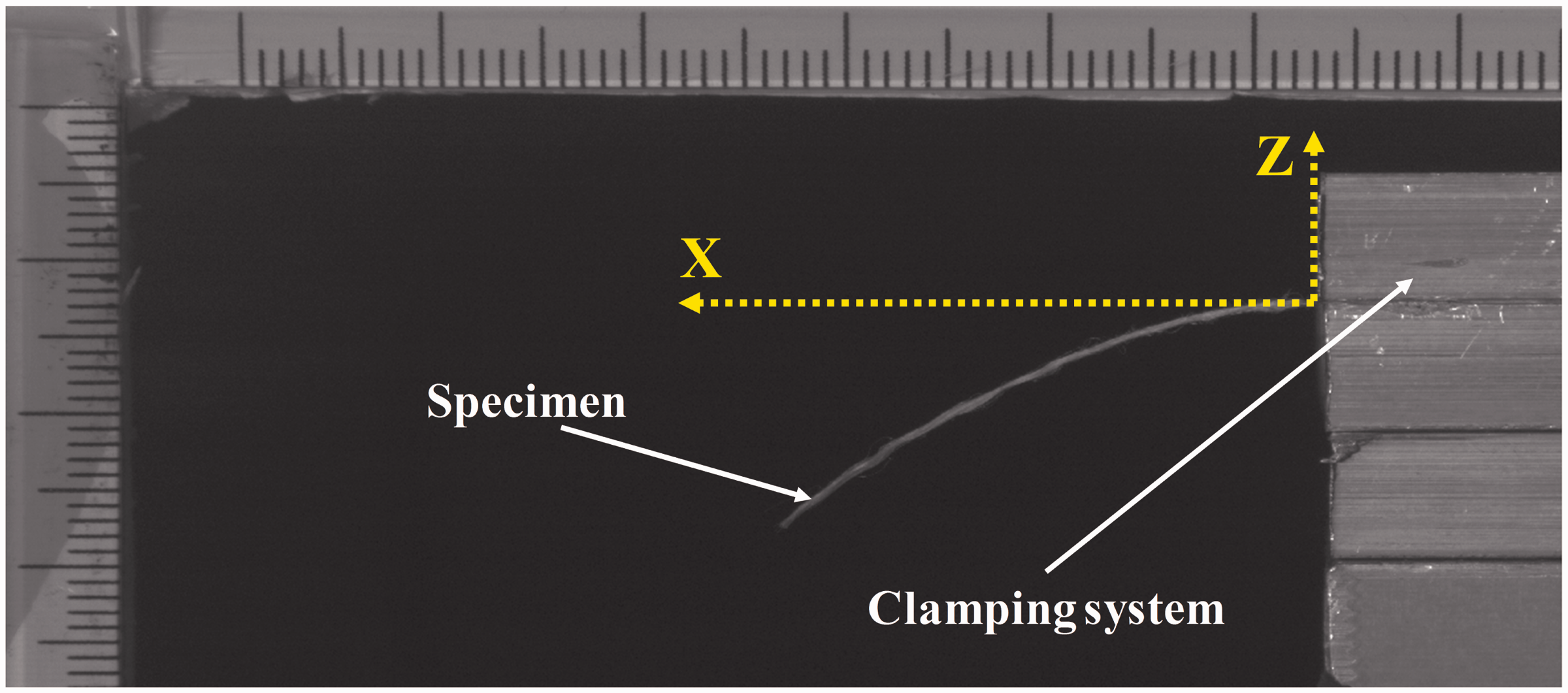
The cantilever setup (Figure 7) was firstly proposed by Peirce [33]. The curvature χ is calculated by (see e.g. Carvelli et al. [26])
Bending test setup (minor ticks are in mm).
Yarns
All the yarns were extracted from the tetraxial fabrics. Three replicates were made for each direction (warp, weft and diagonal). Four different lengths (30, 40, 50, and 60 mm) were adopted for PET, glass, aramid, and basalt yarns.
Textiles
The strips had a width of 50 mm, and four different lengths were considered (30, 40, 50, and 60 mm). Fabrics were tested in both warp and weft directions. Three replicates were made for each testing condition.
Friction testing
The contact behaviour of the yarns is of importance both in the manufacturing process and for numerical modelling of the mechanical behaviour of the fabric. In this study, the coefficient of friction between two yarns was measured using the capstan method [34,35]. A first type of yarn is wound around two separate rods; the second type of yarn (which can be the same as or different from the first one) is put in tension using a dead load and pulled over the rods using a dynamometer (Figure 8). Knowing the dead load (W) and the pulling load (T) the coefficient of friction is readily calculated using the Amontons’ law
Yarn-to-yarn coefficient of friction test setup.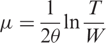

Results
In the first paragraph of this section, the behaviour (tension, bending, and friction) of PET, glass, Aramid, and basalt yarns extracted from tetraxial fabrics is presented. The mechanical behaviour of tetraxial hybrid fabrics is discussed in the following paragraph in terms of in-plane uniaxial and biaxial tensile testing and out-of-plane bending testing.
Yarns
Tensile
The tensile specific stress versus strain curves of the yarns were obtained using the free length as a base length for strain calculation. PET shows a nonlinear behaviour (Figure 9a), which is related to the rearrangement of the fibres and their subsequent alignment in the loading direction. On the other hand, basalt, glass, and aramid have almost linear behaviour with some nonlinearity appearing only at stress levels very close to failure (Figure 9b–d).
Specific stress vs. strain curves for yarns extracted from tetraxial fabrics: (a) PET in the three principal directions; (b) aramid; (c) glass; (d) basalt. Aramid, basalt, and glass are extracted from weft direction only.
Average specific strength of yarns (cN/tex). (± indicates standard deviation).
Bending
The average vertical displacement, z, as a function of the distance from the clamp, x, of different yarns extracted from the weft direction of the fabrics was measured by image analysis (Figure 10). The data were fitted by a sixth-order polynomial function, defined as
Sixth order polynomial fitting of bent yarn specimen shape extracted from tetraxial fabrics in weft direction with different overhanging length. (a) PET, (b) glass, (c) aramid, and (d) basalt. Average and standard deviation (error bars) of three replicates.

The quality of the fitting is related to the coefficient of correlation R2. Values of R2 close to 1 confirm the reliability of the fitting. All fittings of the experimental measurements have the coefficient of correlation higher than 0.98. The average bent profile, in Figure 10, was estimated by the polynomial shape of each test.
Figure 11 shows the curvature and the bending moment at the clamp position for overhanging lengths, ranging from 30 to 60 mm. As expected, aramid has highest and PET has lowest bending stiffness (Figure 11c). The bending stiffness of glass and basalt yarns are quite similar instead.
Bending behaviour from average profile of PET, aramid, basalt, and glass weft yarns: (a) curvature vs. overhanging length; (b) bending moment vs. overhanging length; and (c) bending moment vs. curvature.
Friction coefficient
Yarn-to-yarn friction coefficient was measured for the following combinations of yarns: PET on PET, PET on aramid, PET on basalt, and PET on glass. Specimens were extracted from coils adopted for the weaving process.
Tests were conducted using three different sliding speeds (100, 200, and 500 mm/min). The friction coefficient of PET on PET turned out to be slightly higher than that of PET on aramid and basalt, while glass yarns had the lowest friction coefficient with PET (Figure 12). The differences depend on the roughness of the yarns surface. Glass yarns has smoother surface, compared to PET (see e.g. Palanikumar et al. [36] and Xu et al. [37]), leading to a reduced coefficient of friction.
Values of the coefficient of friction as a function of the sliding speed varying yarn combinations.
Textiles
Uniaxial tensile
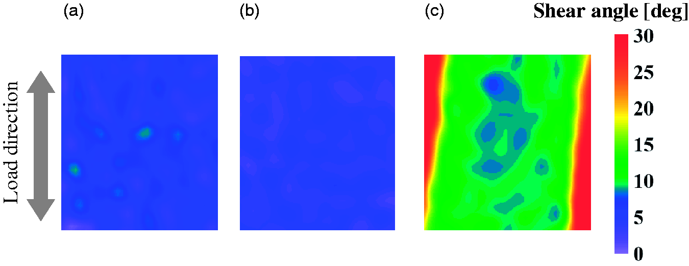
The mechanical properties of the tetraxial fabric can be modified by varying the material of the yarns used in the three principal directions (warp, weft, and bias) and the yarn number per unit length. Figure 13 shows this effect on the tension–strain curves of the hybrid tetraxial fabrics at varying weft threads and loading direction. Here, as for the case of biaxial loading, tension is equal to the recorded force divided by the specimen width. The average surface strain is computed by DIC on an area of 50 × 50 mm2 at the centre of the specimen. For load levels, lower than 200 N, P-P fabric shows an almost isotropic tensile behaviour, while for higher loads the curves differ significantly. The difference may be attributed to the higher crimp of the diagonal yarns possibly leading to higher stress concentration in the cross-over point. In addition, the damage induced on the yarns by the weaving may play a role, as already discussed in Section ‘Results: Yarns’. Contour maps of the shear angle (Figure 14) and the strain component in the direction of the applied load (Figure 15) show almost uniform distributions (apart from some boundary effects) but different deformation levels depending on the loading direction. For a load level of 350 N, for example, the shear angle in the bias direction is about 15°, while in the warp and weft directions is less than 5° (Figure 14).
Tension vs. strain curves of: (a) P-P; (b) P-G; (c) P-A; (d) P-B. Glass, basalt, and aramid yarns are in the weft direction only. Contour plot of the DIC-measured shear angle distribution of P-P tetraxial fabric at 350 N: (a) warp, (b) weft, and (c) bias direction. DIC maps of the strain component in the load direction for P-P tetraxial fabric loaded with uniaxial tensile load of 200 N in: (a) warp, (b) weft, and (c) bias direction.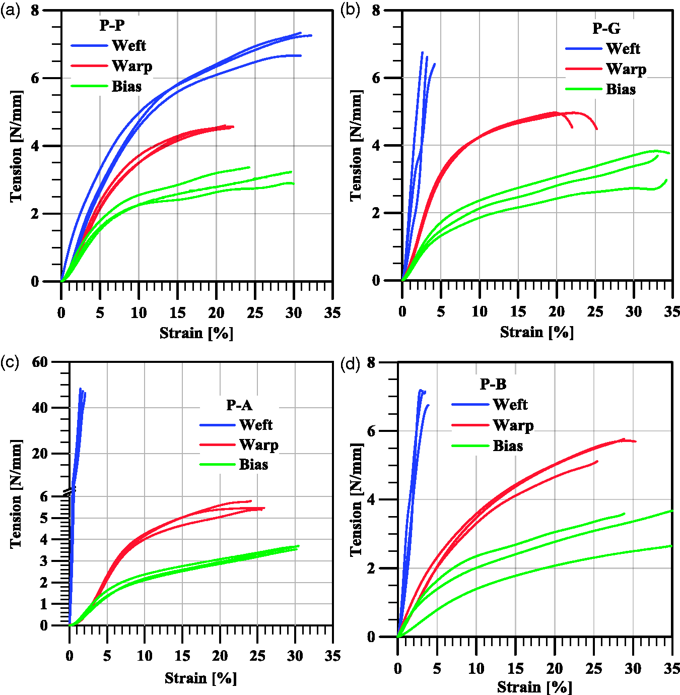

Biaxial tensile
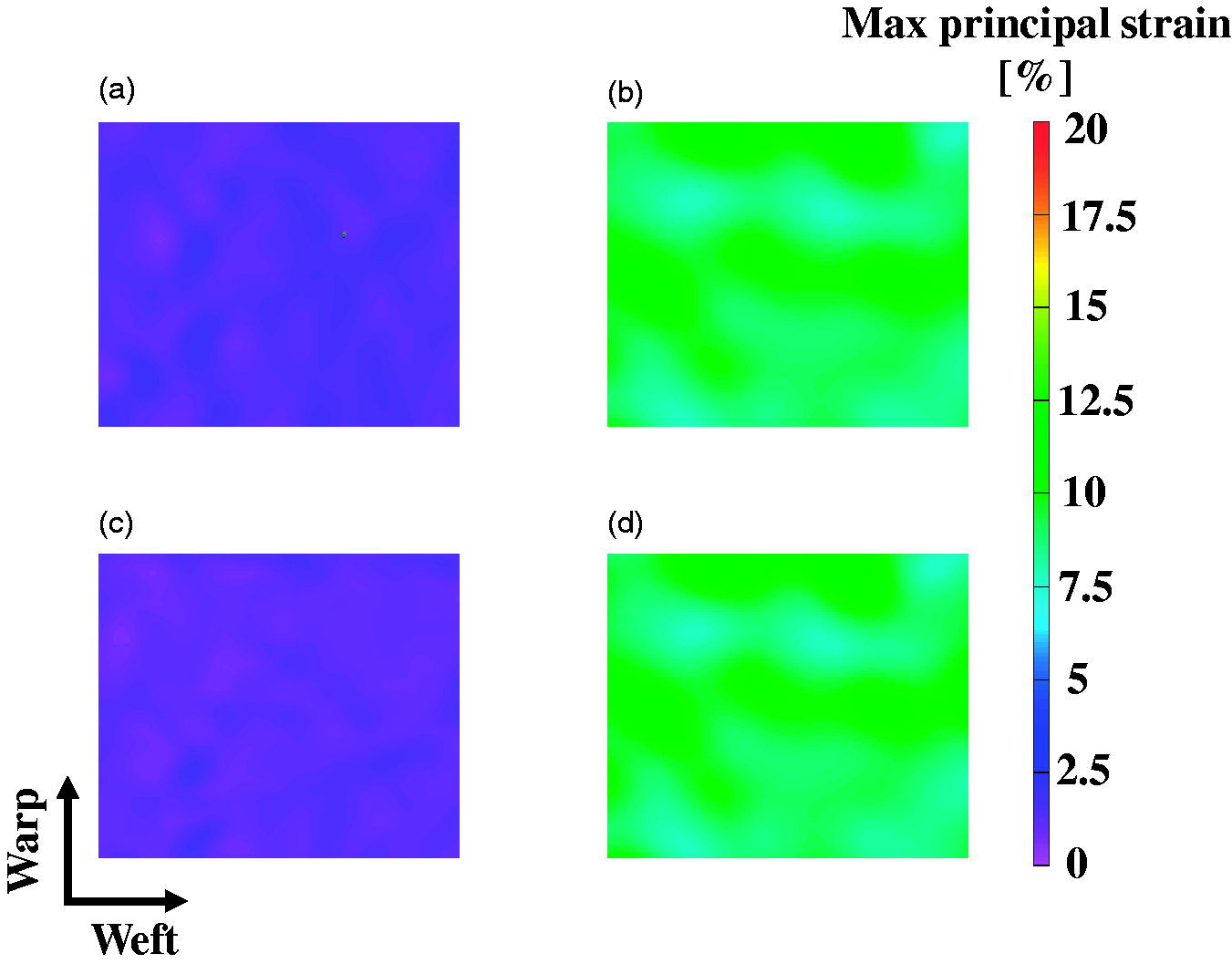
The tension versus strain diagrams for uniaxial and biaxial tensile tests on tetraxial P-P and P-A fabrics upon variation of the warp-to-weft displacement rate ratio R (R = 1/0, 0/1, 1/1, 1/2, 2/1) are shown in Figure 16. As for P-P textiles, the overall mechanical behaviour is not significantly affected by the displacement rate ratio, R, the only difference being observed in comparison with the uniaxial tests (Figure 16a and b). The same is observed for the P-A fabric in the warp direction (Figure 16c), while all curves are very close to each other in the weft direction, due to the higher properties of the aramid yarns, which dominate over the polyester (Figure 16d). Negligible in-plane rotation of the yarns upon varying the ratio R (Figure 17) and an almost uniform distribution of the deformation (Figure 18) is observed for P-P fabric at both low and high loading levels.
Biaxial and uniaxial tensile test of tetraxial fabrics. Representative tension vs. strain curves for ratio R = 0/1, 1/0, 1/1, 1/2, and 2/1: P-P in (a) warp and (b) weft direction; P-A in (c) warp and (d) weft direction. Biaxial tensile test of P-P fabrics. Maps of the shear angle for ratio R = 1/1 and 1/2: (a) R = 1/1, warp load 2 N/mm, and weft load 1.65 N/mm; (b) R = 1/1, at failure; (c) R = 1/2, warp load 2 N/mm and weft load 3.8 N/mm; (d) R = 1/2, at failure. Biaxial tensile test. Maps of the maximum principal strain of P-P fabrics for ratio R = 1/1 and 1/2: (a) R = 1/1, warp load 2 N/mm and weft load 1.65 N/mm; (b) R = 1/1, at failure; (c) R = 1/2, warp load 2 N/mm and weft load 3.8 N/mm; (d) R = 1/2, at failure.

Bending
The bent shape of tetraxial fabric specimens at varying the overhanging length, L, for both warp and weft directions, and the relevant curvature and moment curves at varying the overhanging length are shown in Figure 19 and Figure 20, respectively. As for fibres, the digital measurements of bent shapes were fitted by a sixth-order polynomial function (see Section ‘Results: Yarns’) with coefficient of correlation R2 > 0.98. The average bent profile (Figure 19) was estimated by the polynomial shape of each test.
Sixth-order polynomial fitting of tetraxial fabric specimen bent shape at varying overhanging length. P-P fabric, warp (a) and weft (b); P-A fabric, warp (c) and weft (d); P-G fabric, warp (e) and weft (f), and P-B fabric, warp (g) and weft (h). Average and standard deviation (error bars) of three replicates. Bending behaviour of tetraxial fabrics; curvature vs. overhanging length in warp (a) and weft (b); bending moment vs. overhanging length in warp (c) and weft (d); curvature vs. bending moment in warp (e) and weft (f).

The curvature increases linearly upon increasing the overhanging length for all fabrics considered, but the slope is different in warp and weft directions; some effect of the weft yarn type on the bending curvature in the warp direction is also observed (Figure 20a and b). Moreover, the curvature in the weft direction is not affected by the overhanging length for both basalt and aramid yarns, which was not observed for single yarns (Figure 11a). Besides, PET fabric shows similar bending moment in both directions (Figure 20c and d), while the curvature in the warp direction is more than double with respect to the one in weft direction (see e.g. the overhanging length 50 mm). Therefore, the out-of-plane bending behaviour of PET fabric reflects the anisotropic behaviour in the two main principal directions as observed for tensile loading.
The value of the bending stiffness of the fabrics can be obtained by plotting the moment as a function of the curvature (Figure 20e and f). Full PET fabric has the lower bending stiffness in the warp direction, while all other fabrics have approximately the same value. In addition, as expected, P-A and P-B have higher bending stiffness in the weft direction as compared to P-P and P-G (Figure 20f).
As expected, the tetraxial interlacement creates a complex interaction between the four yarns with a large contact surface. A macroscopic consequence is the constraint of the relative movement of yarns and the drastic increase of the bending stiffness of the fabric (Figure 20f) comparing to the yarn (Figure 11c).
Conclusions and future developments
In this work, a novel loom was adopted to produce hybrid tetraxial textiles using yarns of four materials (PET, glass, aramid, and basalt). An interesting feature of the loom is the possibility of using a wide range of materials and yarn densities to produce hybrid tetraxial fabrics for several industrial applications.
The experimental investigation was conducted in two phases. The first phase covered the mechanical properties of the yarns (tensile, bending) and the measurement of the friction coefficient between different yarns. The second phase dealt with the in-plane uniaxial and biaxial tensile behaviour and the out-of-plane bending response of the hybrid tetraxial fabrics.
The weaving process has proven to be very severe for aramid fibres (which loose approximately half of their tenacity), moderately severe for basalt (35% reduction) while the other fibres (PET and glass) retain their original tenacity. Further investigation is needed to better understand the damage imparted on the yarns during the weaving process. This change, however, is not retained in the textile: the strength of all tetraxial fabrics is much lower than can be expected from the properties of the yarns. This is the proof of the complex interaction between yarns in tetraxial fabrics.
The more pronounced difference in bending stiffness of the fabrics as compared to that of the single yarns demonstrates that tetraxial fabrics have a tight interlacing between yarns. This is expected to have a significant effect on the out-of-plane properties like tear, drapability, and penetration resistance.
A numerical model (based on the finite element method) has been developed to predict the mechanical behaviour of tetraxial textiles upon variation of several parameters, namely, yarns material and spacing in the four directions. Experimental mechanical properties of the yarns and their contact interaction will be used as input for the model; the measured in-plane and out-of-plane mechanical behaviour of the fabrics will be compared to assess the accuracy of the predictions.
The final goal is to optimize the mechanical response of tetraxial fabrics for different industrial applications without having to produce and test several prototypes.
Footnotes
Declaration of Conflicting Interests
The author(s) declared no potential conflicts of interest with respect to the research, authorship, and/or publication of this article.
Funding
The author(s) disclosed receipt of the following financial support for the research, authorship, and/or publication of this article: The work was supported by the Italian Ministry of Economic Development under the research project “Tetraxial” (Grant No. MI01_00202).