
Abstract
The fiber with higher thermal conductivity is rare and it is difficult to measure the thermal conductivity of a single fiber. In this paper, the composite samples of ultra-high molecular weight polyethylene (UHMWPE) fiber and epoxy resin were prepared in order to study the heat conducting properties of the UHMWPE fiber. The specific heat capacity and thermal conductivity of the samples were tested by the transient plane source method. Based on the serial–parallel equivalence theory model, the axial and radial thermal conductivities of the UHMWPE filament were calculated. Effects of the volume fraction of fiber, fineness and drawing ratio on thermal conductivity were explored. Also, the relationship between the structure and thermal conductive capacity was revealed. The results showed that the volume fraction of fibers should be large to obtain a relative accurate value. Moreover, the difference in fineness led to different thermal conductivity of the UHMWPE fiber, the cruder the fiber, the higher the thermal conductivity. Besides, as the drawing ratio increased, the crystallinity and orientation of the fibers also increased. Thus, the results were that the axial equivalent thermal conductivity of the filament was dramatically increased, while the radial equivalent thermal conductivity grew a little. The paper showed that UHMWPE fibers had much higher thermal conductivity than other fibers, and also provided a new method to get the thermal conductivity of UHMWPE single fiber.
Introduction
Ultra-high molecular weight polyethylene (UHMWPE) is one of the three most typical high-performance fibers, which is widely used in fields such as national defense, aerospace, tank armour, etc. [1,2]. Additionally, it also plays an irreplaceable role in transportation, mining, agriculture, construction, machinery, textile, food, chemical, medical, sports and many other fields [3–5]. Many researches had been carried out on the mechanical property, corrosion resistance, chemical stability and wear resistance of the UHMWPE fiber [6–10]. The thermal conductivity of UHMWPE is mainly focused on the addition of inorganic nano powders with good thermal conductivity, such as boron nitride [11], carbon nanotubes [12], p-type bismuth telluride [13], POSS-g-SiCp [14], etc. However, the thermal conductivity of UHMWPE single fiber has not been reported. With the development of science and technology, traditional thermal conductive material has been unable to meet the needs of the modern society. Metal materials possess excellent thermal conductivity, while they are limited to be used in some areas such as chemical production, wastewater treatment, and electronic and electrical fields due to their poor corrosion resistance and preferable conductivity. Additionally, the thermal conductivity of the conventional fibers are general ranging from 0.024 W/(m·K) to 0.337 W/(m·K) [15], which mostly belong to thermal insulation materials and cannot satisfy the requirement of the abovementioned areas. In contrast, thermal conductive polymer materials with the outstanding insulation and thermal conductive properties [16] meet the needs of some specific domains well. Therefore, the study on thermal conductive polymer materials is of great significance.
The vast majority of inorganic non-metallic materials cannot be a thermal carrier, because its electrons are bound, so it cannot use the electronic heat conduction mechanism to explain the dielectric heat conduction phenomenon. In the lattice of non-metallic crystals, free electrons are few, so lattice vibrations are their main thermal conduction mechanism. According to the quantum theory, the energy of the lattice vibrations is quantized, and the “quantum” of the lattice vibration is usually called “phonon”, so thermal conduction process of the dielectric can be described by phonon concept. As there is no electron flow the thermal conductivity of polymer materials is 500–1000 times lower than the metal materials, and there are only very few polymer materials with good thermal conductivity. Compared with metal and inorganic materials, most macromolecules are saturated systems, which is no free electrons exist and molecular motion is difficult, so heat conduction is mainly the result of lattice vibration, and phonon is the main thermal loader [17]. Ultra-high molecular weight polyethylene is a typical polymer with high thermal conductivity, its fiber has a high degree of crystallinity (>98%). The heat conduction is also through the thermal vibration between the proton, resulting in heat conduction phenomenon.
As fiber is obviously anisotropic and the single fiber has a large length-to-diameter ratio and small diameter (less than 100 µm) it is difficult to test directly the thermal conductivity of single fiber using the existing test methods. For example, Wang et al. [18] tested the heating of single carbon fibers in the axial thermal conductivity of 84.35 W/(m·K) by the T-type test method. Wang et al. [19] tested the vertical axial thermal conductivity of the polar bear fiber bundles which is in the range of 0.02785–0.05464 W/(m·K) by the transient hot-wire indirect method. The direct test method depends on the length and strength of fibers. Usually, natural fibers do not meet test conditions because of its limitation of length. The method of indirect test is meant to solve the problem of infeasibility in direct test. The thermal conductivity of single fiber is conducted by the establishment of fiber assembly idealized model and theoretical calculation. The result can be used as a reference for the thermal properties of fibers, but there will be certain equivalent error.
In order to obtain the axial and radial thermal conductivities of the UHMWPE fiber, a new method was developed based on transient plane source (TPS) to get the thermal conductivity of single fiber. The UHMWPE fiber and epoxy mixture samples were made where the fibers were arranged parallel or vertically. Based on the two-phase composite media serial–parallel equivalent thermal conductivity physical model, the TPS method was applied to test the two-phase composites of epoxy resin and UHMWPE fiber and then calculate the axial and radial equivalent thermal conductivities of UHMWPE single fiber. The relationship between the structure [20] and its axial, radial thermal conductivities of UHMWPE fiber was also explored. These researches will provide a new method to get the thermal conductivity of single fiber and point out the higher thermal conductivity of UHMWPE single fiber and its impacting factors.
Experimental
Experimental material
The parameters of applied materials.

The draw ratio corresponds to the subsequent drawing of the raw silk.
Sample preparing
The UHMWPE fiber was filled in a mold (inner diameter 18 mm) in vertical parallel state. The solution was obtained by mixing epoxy resin (GCC-135, epoxy value: 0.54–0.6 equivalent/100g; viscosity: 700–1100 mPas; density: 1.13–1.17 g/cm3) and solidification agent (GCC-137, amine value: 400–600 mg KOH/g; viscosity: 10–50 mPas) in the ratio of 3:1, stirred well and vacuumized to eliminate the small bubbles in solution. The mold filled with parallel fibers was perfused with the mixed solution by using the vacuum pump to extract it from the bottom to top which ensured that the air in the samples was cleared out. To avoid the influence of heat treatment process on the heat transfer performance of UHMWPE fiber, room temperature curing method was adopted. The cured samples of mixed epoxy and parallel fibers were cut into the required specifications with a smooth section. Finally, the mold shell was removed off and the samples were obtained. Figure 1 shows the curing sample model schematic diagram of UHMWPE fiber bundles, where (a) is the sample schematic of UHMWPE fiber cured by epoxy resin; (b) is the cross-section of solidified samples and (c) is the schematic diagram of the separated cell body made of single fiber.
The schematic of UHMWPE fiber bundle cured sample: (a) UHMWPE fiber cured diagram; (b) cross-section and (c) cell unit of single fiber.
Each sample was prepared into two different kinds of forms which were used to test the specific heat capacity and thermal conductivity rate. The samples of two forms were both cylindrical and the diameter was 18 mm. The preparation process and the content of resin and fiber in the same sample (the specific heat module and the heat conducting module) were the same, but they differ in thickness. The specific heat module sample was 5 mm in thickness and 18 mm in diameter, as shown in Figure 2(a). The requirements of the thermal conduction module sample were as follows: the thickness should be 1.2α (3.8268 mm), the diameter should be larger than 2.4α (7.6536 mm), where α is the radius of the probe. The type of the probe was 5465 (α is equal to 3.189 mm). The thickness and diameter of the thermal conductive module sample were 18 mm and 18 mm, respectively, as shown in Figure 2(b).
Schematic block diagram of the test sample: (a) the specific heat testing module sample and (b) thermal conductivity testing module sample.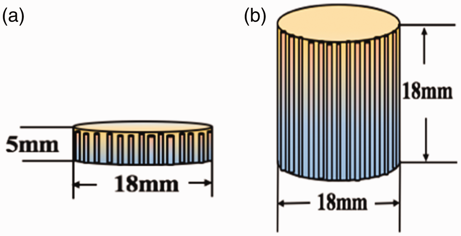
Test method
X-ray diffraction (XRD) measurements were conducted for UHMWPE fibers with different draw ratios at room temperature using D/Max-2550P product of Rigaku Corporation, Japan, which has copper target, monochromator and scan speed of 2°/min.
Using the SCY-III sonic orientation degree measuring instrument, the sonic orientation factors (Fs) are measured for UHMWPE fibers with different draft ratios

The breaking strength and elongation at break were measured using Instron 5567. The results were the average of 10 measurements according to GB/T 19975-2005.
The hot disk thermal constant analyzer was employed to examine the epoxy resin and UHMWPE fiber two-phase composites. First, the volumetric specific heat of the samples was tested and the size is shown in Figure 2(a). The sample was placed into a metal shell with a sponge covering on both sides, and a certain pressure was exerted on it. Subsequently, the two samples with the same size (shown in Figure 2(b)) were placed axially at both ends of the probe, then the thermal conductivity of the sample was tested. During this process, the TPS probe was arranged between the two samples, with both ends exerted on the certain pressure to narrow the gap between the probe and the sample. The positional relationship between the probe and the sample is shown in Figure 3. Once the samples were placed and fixed, a cylinder carpet was covered to avoid the interference of air flow with the sample temperature.
TPS positional relationship between the probe and the two samples.
The anisotropic module was employed in the test. When the probe was placed between the two identical samples, it released heat which was evenly spread around and the system recorded the relationship between time and the increase of the axial/radial electrical resistance (temperature) of UHMWPE fiber samples, thus the axial and radial experimental parameters were got. According to the above approach, the thermal conductivity and thermal diffusion coefficient of the samples were calculated by a single recording of the transient change. The detailed analysis of the principle of TPS method has been given in our previous work [21], and it is necessary to summarize the calculation progress of the equivalent theory as follows.
Equivalent theoretical calculations
In order to acquire the equivalent thermal conductivity of UHMWPE single fiber, the epoxy resin UHMWPE fibers composite samples, the two-phase parallel model and two-phase serial model were considered as the simplest and effective models. Based on the two models, the equivalent thermal conductivity of UHMWPE single fiber was calculated. Let component 1 and component 2 represent the UHMWPE fiber and resin, respectively. V1 represents the ratio of the volume of component 1 to the total volume of the sample.
As shown in Figure 4, the heat flux is parallel to the interface of the two components, which shows that the heat transfers along the longitudinal direction (corresponding to the “L” direction in Figure 4) in the two-phase parallel model. As a result, this model can be considered as the heat flow path with two different thermal resistances. In the following equation, the thermal conductivity of the model is λb, the thermal conductive coefficient of component 1 and component 2 are λ1 and λ2, respectively
Pure parallel model.

According to equation (1), when λ1 is larger than λ2, λ1/λ2−1 will be far greater than zero; therefore, the change of volume ratio will significantly influence the calculation results. Thus, the equivalent thermal conductivity increases with the increase of the volume ratio. If the value of λ1/λ2 is greater than one, the equivalent thermal conductivity increases with the increase of volume ratio, and when the value is smaller than one, the equivalent thermal conductivity increases slightly with the increase of volume ratio.
By applying the parallel model to simulate the axial thermal conductivity of the fiber (UHMWPE fiber and epoxy resin are represented as component 1 and component 2, respectively), the equivalent thermal conductivity of UHMWPE single fiber (λ1
b
) can be calculated as

In the pure series model (Figure 5), the heat flux is perpendicular to the interface of the two components, the heat will pass along the component 1 to component 2 in turn and then continues to transfer along different components one after another. This model is seen as a heat transfer channel divided into two layers, and the temperature difference between both ends is the sum of the temperature difference of component 1 and component 2. In the series model, the thermal conductivity (λt) is
Pure series model.
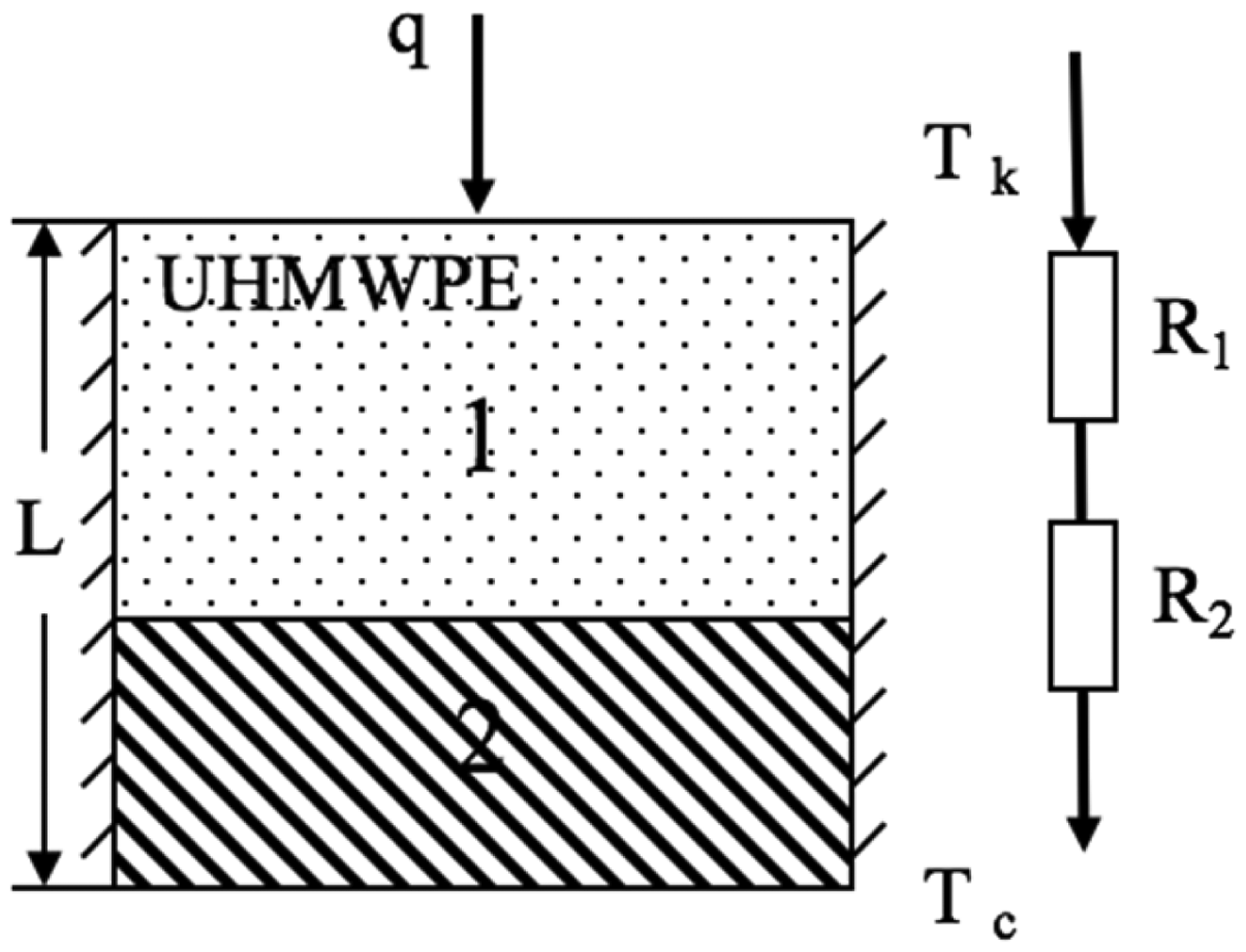
The radial thermal conductivity of the fiber can be regarded as the pure series model to calculate it. Here, the classification of the component is the same as previous. The equivalent radial thermal conductivity of UHMWPE single fiber (λ1
t
) can be calculated as follows

Results and discussion
Thermal parameters of different fiber types
The conventional fiber was tested according to the method mentioned above, and the results were as follows.
The parameters of different fiber types.

The effect of the volume fractions of fiber on thermal conductivity
As mentioned in section ‘Equivalent theoretical calculations’, theoretical calculation results could be affected obviously by fiber volume ratio (V1). In order to obtain a relatively accurate value, the UHMWPE fiber with the single fiber fineness of 10.42 dtex was adopted to fill in the sample with various different volume proportions (as seen in Figures 6 and 7).
The specific heat capacity of samples with different volume fractions of UHMWPE fibers. Equivalent thermal conductivity of UHMWPE fibers with different volume fractions.

As shown in Figures 6 and 7, the specific heat capacity of the sample and the equivalent thermal conductivity of UHMWPE fiber improved with the increase of the volume percentage occupied by UHMWPE fiber, and it was noticeable that the improvement of axial direction was more prominent than that of the radial direction. Moreover, when the volume fraction of fiber was less than 61.92%, the change was great, while the growth was slow when it exceeded by 61.92% which can be attributed to the small thermal conductivity of the pure resin (0.2395 W/(m·K)). When the volume fraction of fiber was small, the resin had great influence on the experimental parameters of the sample, and when the fiber content was larger, the influence of resin was weaker and even to be negligible. In this situation, the experimental parameters were improved mainly due to the increasing of the fiber content. Therefore, the volume fraction of UHMWPE fiber must reach to a certain content in order to ensure the accuracy of the test. Considering the operation feasibility of preparation and the test accuracy, the volume fraction of the fiber in later experiment should be controlled at about 50%. Based on the unified volume fraction of fiber, a relatively accurate proportion value was obtained which was of great significance to our later experiment.
The effect of different fineness on thermal conductivity
Fineness is a very important physical parameter for the fiber. Fibers of different fineness have different thermal resistances. Figures 8 and 9 display the specific heat capacity and equivalent thermal conductivity of UHMWPE fiber samples with different fineness.
The specific heat capacity of different monofilament fineness of UHMWPE fibers. The equivalent thermal conductivity of different monofilament fineness of UHMWPE fibers.

Although UHMWPE fibers with different fineness belong to the same substance, their macromolecules have different structures and arrangements, which can be attributed to different substances, so their corresponding performances are different. As seen from Figures 8 and 9, with the increase of UHMWPE fiber filament fineness, the specific heat capacity and the equivalent thermal conductivity rate were increased, and the axial equivalent thermal conductivity increased more sharply than the radial equivalent thermal conductivity. Thermal conductivity is similar to the resistivity, which refers to the flow rate of heat per unit area under the unit temperature gradient. It is a physical quantity that characterizes the thermal conductivity of a material, which is related to the type of material, the structure and the temperature of the material. The thermal resistance of uniformly distributed UHMWPE fiber is inversely proportional to the cross-sectional area, i.e. the thicker the fiber, the smaller the thermal resistance of the fiber, and the greater the heat flow rate, the better the thermal conductivity.
The effect of drawing ratio on thermal conductivity
UHMWPE has attracted a large number of people to constantly explore novel approaches [22,23] to produce it and improve its physical properties due to the large molecular weight, the winding among the molecular chains and the effect of intermolecular force. It focused on the effect of drawing ratio on the thermal conductivity of UHMWPE fiber. The specific heat capacity and equivalent thermal conductivity of the UHMWPE fiber under different drawing ratios are shown in Figures 10 and 11.
The specific heat capacity of UHMWPE fibers with different draw ratios. The equivalent thermal conductivity of UHMWPE fibers with different draw ratios.

It can be seen that, for the UHMWPE fibers with different drawing ratios, the specific heat capacity and equivalent thermal conductivity increase with the increase of drawing ratio. With the increase of drawing ratio, the axial equivalent thermal conductivity sharply increased, whereas the radial equivalent thermal conductivity increased slightly. Zhang et al. [24] did researches on the effect of heat drawing to the crystal structure of UHMWPE, and found that the UHMWPE undergoing a secondary draft could generate an extended chain crystal of orthorhombic crystal system and the folded chain crystal dualistic structure. When the drawing ratio was 12.2 (Figures 10 and 11), the axial equivalent thermal conductivity of this fiber was 7.86 times as much as that of the original fiber for a considerable number of extended molecular chains were formed in the fiber to construct the needle-like crystals, namely “crystal bridge”. So the heat conduction mechanism can be described as the “crystal bridge” heat conduction mechanism, and the manner of drawing amounted to broaden the width of the crystal bridge, and thus prompted the transmission of the phonon, which increased the thermal conductivity rate.
XRD test of different drawing ratio
The molecular chains of wafer in UHMWPE gel fiber without drafting were arranged vertically on the surface of the fiber. When the molecular chains were stretched in axial direction, it would rapidly align along the drawing direction. If the drawing ratio was large enough, the folded chain crystals would be pulled out from the wafer, which were connected by joining the molecular chains to form a microfiber in the tensile direction in series molecular chains. For in-depth understanding of the relationship between the thermal conductivity and molecular structure of the oriental polymer, the XRD result of UHMWPE fibers with different drawing ratios was analyzed (Figure 12), and its crystallinities and orientation factors (Fs) are shown in Table 3.
XRD pattern of UHMWPE fiber with different draw ratios. The crystallinity and orientation factor (Fs) of UHMWPE fibers with different draw ratios.

According to Figure 12, there were two diffraction peaks of θ at 21° and 23.4° in the XRD curves of the as-spun fiber (UHMWPE original fiber) and the fiber under low magnification tensile, which were corresponding to the crystal surface [110] and [200] of the orthorhombic polyethylene, respectively. When the drawing ratio of the UHMWPE fiber was higher than 10.7, the diffraction peak emerged at 19.1° corresponding to the crystal surface [100] of the hexagonal–cubic crystallography. With increased drawing ratio, the intensity of diffraction peaks at 21° and 23.4° improved, the half peak width narrowed and the diffraction peaks became extremely sharp, which indicated that the crystallization orientation of the fibers became perfect during the drafting process. Furthermore, the fiber macromolecules were oriented and crystallized along the drawing direction with the increase of drawing ratio. The folded chain lamellae, peculiar to the flexible macromolecule, converted into the extended chain crystal structure, and the more the straight chain and the hexagonal–cubic crystallographic contained, the faster the heat was transferred.
The crystallinities and sonic orientation factors of UHMWPE fibers with different draw ratios are shown in Table 3. With the increase of the drawing ratio, the macromolecular chains are stretched and aligned in the axial direction to form the straight chain crystal. The crystallinities of the fiber increases, so that the lattice vibration of the heat transfer increases, and the sonic orientation factors increases, and the thermal conductivity of the UHMWPE fibers increases, which are shown in Figure 11. The axial thermal conductivity of the fiber reflected sensitively by the change of molecular chain orientation and extensional structure. With drawing ratio increased, the macromolecular chains in the fiber were oriented and arranged along with the drawing direction to form the extended chain crystal, which caused the higher axial thermal conductivity than that of the radial. Furthermore, the thermal conductivity increased with the enhancement of the draw increased owing to the increase of the amount of “crystal bridge”. The results showed that UHMWPE fiber possessed large thermal conductivity against the concept that polymers are thermal insulators according to many researchers. Therefore, further researches were expected to break through the traditional concept. And now, a relative high thermal conductivity was achieved only in the axial direction, while it is difficult to get breakthroughs in radial direction which will be defected in the application.
Conclusion
In order to ensure the accuracy of the test, the volume fraction of the UHMWPE fiber should reach to a certain amount. In view of the operability of the sample preparation and the accuracy of the experimental results, the volume fraction of fiber was controlled at about 50% in this paper. The thermal conductivity of UHMWPE fibers varied with different fineness, and it increased with the increasing of fineness. With increased drawing ratio, the axial equivalent thermal conductivity of the UHMWPE fiber was dramatically increased, whereas there was only a slight enhancement in the radial direction. The crystallinity and crystal integrity of the polymer can be enhanced by the heat drafting treatment and the thermal conductivity was also improved. It was found that once the degree of crystallinity of polymeric materials was improved, the thermal conductive properties of them can also be modified through increasing the arrangement sequentially of the internal molecular chain of the materials.
If the UHMWPE fiber is drawn with a high drawing ratio, the lattice will arrange along with the orientation, which facilitates the phonon ordered arrangement along the lattice to transport heat, thus improving the thermal conductivity greatly. However, the increase of thermal conductivity is only in the axial direction of UHMWPE fiber, while it is limited in the radial direction. For some occasions, the thermal conductivity in all directions needs to be enhanced, so the related researches should be further explored.
Footnotes
Declaration of Conflicting Interests
The author(s) declared no potential conflicts of interest with respect to the research, authorship and/or publication of this article.
Funding
The author(s) received no financial support for the research, authorship, and/or publication of this article.