
Abstract
In this paper, the effect of utilizing hollow polyester fibers as reinforcement in composite material in comparison with solids is investigated. The three-point bending impact test is carried out to study the impact behavior and mode of failure of composites. After that, the finite element method is used for theoretical investigation and modeling the behavior of two different reinforced composites during impact tests. It was found that the fiber–matrix interface failure is the most dominant mode of failure and the crack was initiated at the middle of the bottom surface of composites. It was also found that the impact resistance of the hollow fiber composite is more than the others. Theoretical results showed good correlation with experimental results as well. The stress distribution and the maximum value of strain energy density was found as two factors which lead to improvement in the impact behavior of hollow fiber composites.
Introduction
The advantages of hollow glass fiber (HGF) as reinforcement in composite materials have been investigated. Hollow glass fibers have shown higher improvement in the dielectric, thermo-insulating, acoustic insulation and some mechanical properties of composites in comparison to solid fibers.
At first in 1962, hollow glass fibers have been used as reinforcement to improve the bulk properties of polymeric composites [1]. Although a considerable improvement in specific longitudinal compressive strength was observed in hollow fiber specimens compared to solid ones, very low transverse compression strength was obtained. Therefore, it has been concluded that HGF is useful only for shell buckling applications when the material density is important [2].
Hucker et al. [3] have achieved similar results for longitudinal compression strength by producing HGFs with different outside and inside diameters. Boniface [4] has proposed that the compression strength of HGF composite is 20% higher than solid fiber-reinforced composite after impact tests. It has also been found that a hybrid composite of HGF and Nicalon fiber is an appropriate material for structural applications where microwave transparency and high stiffness are both required [5].
Hollow glass fibers are known as a good material for storing the healing components which can restore a considerable amount of lost flexural and compression strengths during impact tests [6–8]. It has been theoretically and experimentally shown that HGF laminates have a flexural rigidity considerably higher than solid ones [9,10]. Zhang et al. [11] have presented a criterion for mode II crack in fiber-reinforced composites. The strain energy density is represented as the main factor for mode II failure in orthotropic composite material.
However, hollow polymeric fibers are not utilized as reinforcement in composites and researches are focused on applying only hollow glass fibers.
Polyester fibers have high strength and appropriate reversibility. They are resistant against abrasion and chemical materials. These features lead to an increase in durability of the composites containing polyester fibers. The polyester fibers are also resistant against weak acids in welding, strong acids at cold condition, and diluted alkaline environment. However, strong and hot alkaline materials will damage them [12]. Since the polyester fibers have higher ductility compared to glass fibers [13], it seems that they can improve the transverse compression strength of composite during compression and impact in comparison to the HGF composite.
In this research, the hollow and solid fully drawn polyester fibers are applied as reinforcement in polymeric composites and their impact behavior is investigated. Then, the finite element method is used for modeling the behavior of composites and studying the mode of failure under impact tests.
Experimental procedure
Materials
Some properties of solid and hollow yarns.

An epoxy resin (polypox VE 01416/5) without any solvent was applied as the matrix. The viscosity of the used resin was 3350 mPa.s.
Specimen preparation
The strand (composed of 72 filaments) was initially impregnated in a resin bath on an industrial filament winding device. Then, it was unidirectionally wound over a mandrel with 10 cm diameter. The mandrel was placed in an oven for 1 h at a temperature of 60℃ for resin curing, when it was completely covered to the desired thickness. Finally, two cylindrical tubes with 4.5 mm wall thickness made up of solid and hollow fibers were pulled out of the mandrels.
In order to prepare the specimens for the three-point bending impact test, the cylindrical composites were cut to some rings with 2 cm width. Afterwards, each ring was cut to four equal pieces with a convex shape (see Figure 1). The specimens were preserved in an incubator at the normal condition to avoid undesired changes in humidity and temperature.
Schematic of the prepared specimens.
Test method
Low-energy/low-velocity impact test was performed on the samples using InstronDynatup 8250 drop-weight impact test machine.
For each composite sample, eight specimens reinforced by solid and hollow fibers were subjected to impact tests by a cylindrical head striker in 5 mm radius. The striker with the same weight (2655 g) was dropped from five different heights to achieve different impact energies. The contact load during the impact test was measured with a 5 kNKistler load cell (9001 A) located on the falling tup and recorded with a Yokogawa DL 1540 digital oscilloscope. The displacement of the head was measured using a Meter Drive ZAM 301 AAS linear encoder with the resolution of 0.1 mm. The span length was 60 mm.
Experimental results
Some physical and geometrical properties of composites.

Figure 2 demonstrates the created cracks at the back surface of both specimens after impact tests. It is evident that the most dominant mode of failure is the interface failure in the investigated polymer fiber composites.
Interface debonding at the back surface of the cracked specimen. (a) Solid fibers and (b) hollow fibers [14].
Results of absorbed energy obtained from impact test.

r = Density.
It should be noted that the specific absorbed energy is defined as the value of energy absorption which has been normalized by density. It is evident that the specific energy absorption in the hollow fiber samples is higher than the solid one.
It is found that the impact energy is initially absorbed by the elastic deformation of the specimen prior to the energy value at which the crack is initiated. Therefore, the superiority of the hollow fiber composite in energy absorption might be due to the hollow fibers’ slight elastic elliptical deformation which led to energy dissipation in the form of heat.
Results of impact tests also showed that the number of damaged specimens is increased for both composites by increments in the impact energy. It should be noted that a microscope was used to investigate created damage in cross section of all the samples. Therefore, all the micro cracks were considered. It is found that a single crack is created in 50% of the solid fiber composites at the impact energy of 2.91 J, while this damage percentage has been obtained at 5 J for hollow fiber ones. This is while the hollow fiber composites have a lower modulus compared to other specimens. Therefore, the hollow fiber composite is more resistant against impact forces in comparison to solid ones (see Figure 3).
Maximum deflection–impact energy curves.
Maximum force and deflection of composites under impact test.

The higher values of maximum force of solid fiber specimens reveal the higher modulus and therefore flexural stiffness of these composites in comparison to hollow fiberones.
Impact process modeling
Three steps of finite element modeling using ABAQUS 6.10 software have been used in this section to analyze the stress distribution at the fiber–matrix contact zone. At first, the entire composite material has been modeled using the micromechanics method and the representative volume element and then the engineering constants have been calculated in order to utilize in the macro model. At the second step, the obtained results have been used as the input for the mechanical properties definition, in order to model the impact process on the composites. According to experimental studies, the failure occurs in the form of fiber–matrix debonding on both hollow and solid fiber-reinforced composites. Therefore, it is important to investigate the stress distribution at the fiber–matrix contact zone. Thus, at the final step, the results of the stress–strain analysis obtained from the second step have been used as the inputs for micromechanical modeling of fracture zones. Thus, it is possible to study the reasons of differences in impact strength of two different composites.
Calculation of tensile and shear modulus and Poison’s ratio
The behavior of composites containing hollow and solid fibers under longitudinal, transverse and shear loadings is investigated, using the finite element method. The representative volume element is used in order to model the composite (see Figure 4).
Schematic of representative volume element in unidirectional fiber-reinforced composite.
The remaining stress value in the fiber–resin interface is ignored as the thermal expansion coefficient of the epoxy and polyester is nearby [15].
The stress and strain equations are used and the force (F) is obtained from the model to calculate the tensile modulus (E) in three directions using equation (1)


The Poison’s ratio is also calculated from transverse over axial strain.
Three point bending impact test
The stress and strain distribution in the bottom surfaces of the composite under impact force is investigated. The material properties are defined as orthotropic properties to simulate the one-directional fiber-reinforced composite. Therefore, the stress and strain values in the main direction are calculated using equation (3)
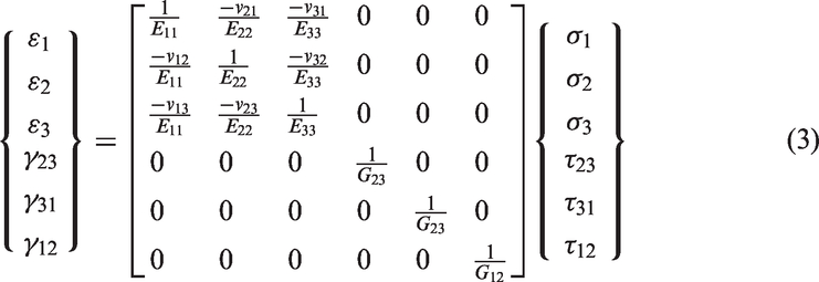
As the material is isotropic in the transverse direction of unidirectional composite, we have

Boundary conditions and applied loading in drop weight impact model.

S.C.: solid composite, H.C.: hollow composite.
The kinetic energy of the striker is assumed as 5 J which is obtained from the experimental tests.The kinematic contact algorithm which is more similar to the real conditions in case of loss energy is applied in this model.The element C3D8R which is meshed structurally is selected for modeling the specimen under impact force in ABAQUS software. This element is a three-dimensional element with eight nodes and three degrees of fredom in each node.The element R3D4 which is a three-dimensional rigid element with four nodes is also used for modeling the rigid supports and striker.
Stress in fiber and matrix contact zone
A modeling is performed at the middle point on the bottom surface of the composite (see Figure 5).
Boundary conditions and applied strain in representative volume element at the free surface of hollow fiber composite.
The boundary conditions are defined symmetrically on the BC side. The transverse strain which is defined as displacement in X direction on the S side is considered as 0.56% and 0.51% for hollow and solid fibers composites, respectively. 2D modeling of the representative volume element (CPEG4R) as planar strain was used due to the long length of composite material in the fibers direction. The elements are selected as non-structural four-node elements for the matrix and the solid fiber though the structural element is opted for hollow fiber.
Elastic strain energy density in the fiber and matrix contact zone
Generally, it is assumed that in the investigation of fracture mechanics of materials, all materials with unstable crack propagation have had a structural defect before crack initiation which is the region that crack initiates and propagates from there. Therefore, it is necessary to determine the place, size, configuration and direction of the defect or initiated crack to present an appropriate analysis of the fracture process. Strain energy density is a more comprehensive criterion that determines the disposed zone for fracture and analyses of the fracture process without any relation to the crack or initiated defect [11].
The absorbed energy in the specimen during deflection, which is defined as strain energy, is calculated from the surface area under load–elongation curves (equation (5))
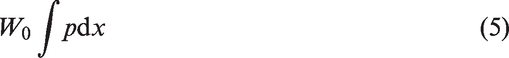
where W0 is the absorbed energy in the specimen, P is the applied force, and x is the deformation.
Strain energy density, the strain energy per volume unit of specimen, is calculated as the surface area under stress–strain curves and for elastic material it is obtained from equation (6)

To compare the strain energy density in the fiber–matrix contact zone, for both specimens a distinctive path containing some nodes on the matrix boundary side is defined (see Figure 6).
The considered path for von Mises stress calculation.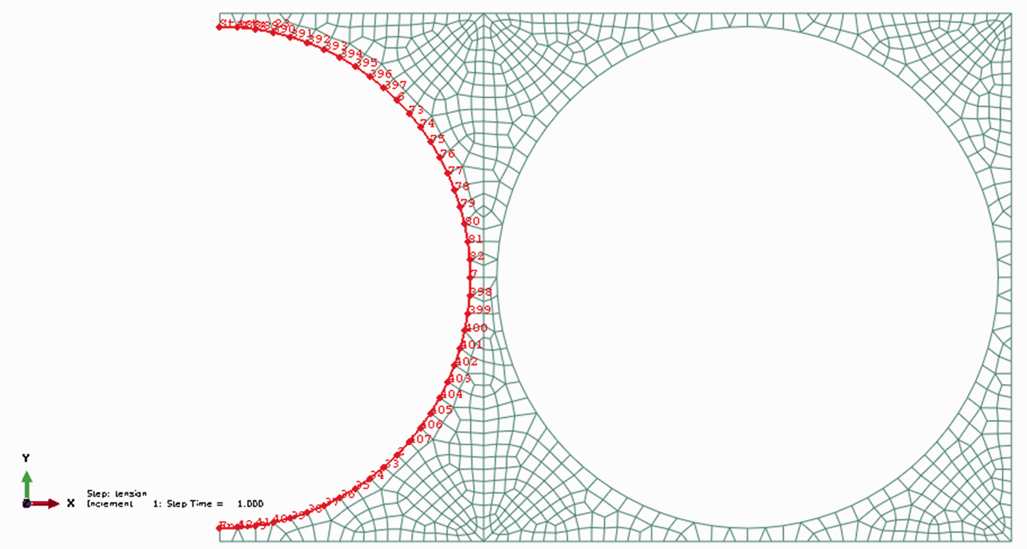
Modeling results and discussion
Calculation of engineering constants
The engineering constants for both hollow and solid fiber-reinforced composites.

Three-point bending impact test
The stress and strain distribution in the bottom surface of the composite under impact force is investigated to find the main reason of failure and to distinguish the reason in differences of impact force capability between hollow and solid fiber composites.
As illustrated in Figure 7, the composite layer shows transverse strain in the bottom surface in addition to longitudinal bending. The maximum value of this strain is at the middle of the composite and it is calculated as 0.51% and 0.56% for solid and hollow fiber composites, respectively. Although the transverse strain value is less than the longitudinal strain value which was about 7.4%, it may lead to failure in the bottom surface of the composite.
(a) Transverse strain distribution in one-directional filament winding composite and (b) mode of deformation in curved beam under impact force.
Figure 8 shows the contact force–deflection curves for both solid and hollow fiber-reinforced composites under 5 J impact energy. It is observed that the configuration of the curves obtained by finite element method is similar to the experimental curves. A decrease in the theoretical curves widths is related to the linear elastic assumption for the specimens under impact force in the modeling process.
Contact force–deflection curves for two specimens under impact force. (a) Solid fiber composite and (b) hollow fiber composite.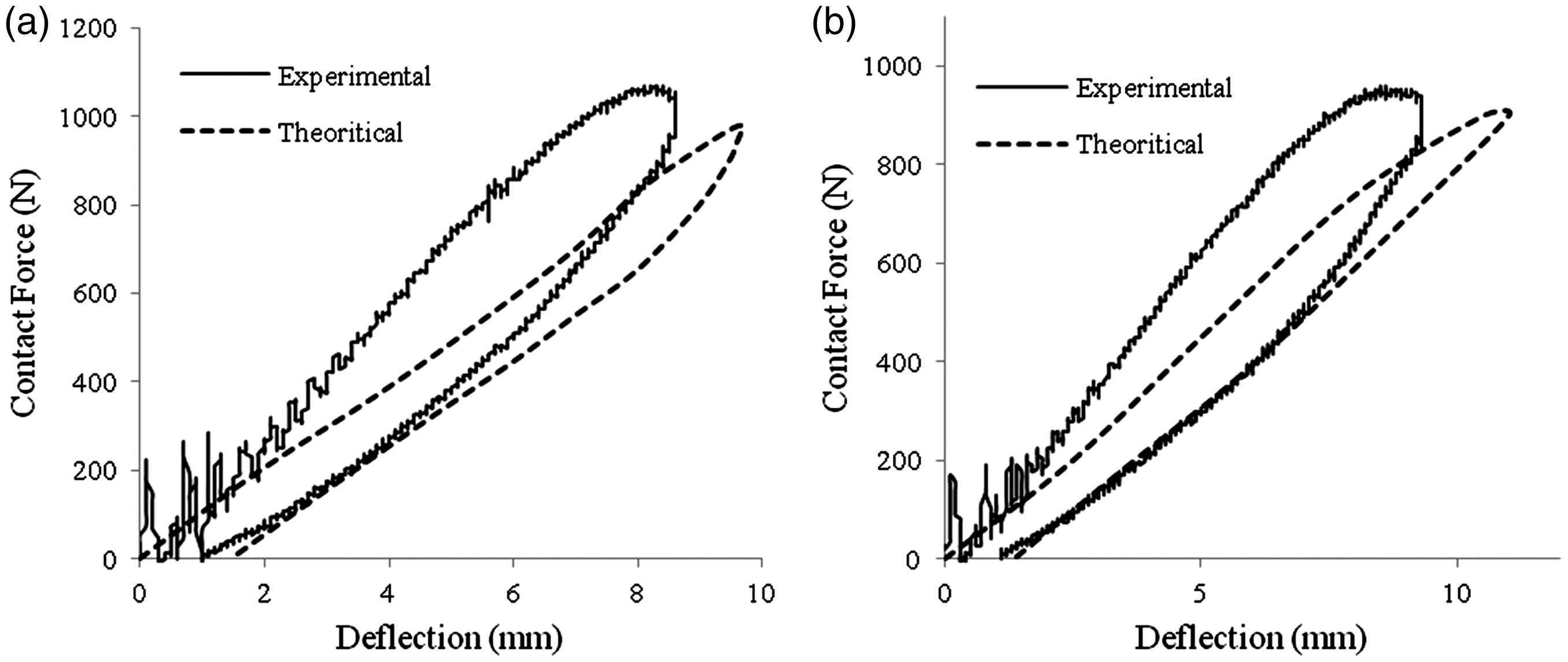
Maximum force and deflection of experimental and theoretical analysis.

It should be noted that the differences between maximum deflections of solid and hollow fiber composites are 5.3% and 4.3% for theoretical and experimental methods, respectively. Therefore, it is possible to consider that the presented model is a valid model because of the proximity of the two different methods’ results and it will be valid for analysis of transverse strain in the bottom surface of the specimens.
Stress distribution
In order to investigate the reason for the greater resistance of the hollow fiber composite under the three-point bending impact test, a modeling is performed at the middle point on the bottom surface of the composite. Figure 9 shows the von Mises stress distribution in the free surface element of hollow and solid fiber-reinforced composites.
von Mises stress distribution in the representative element of hollow (a, b) and solid (c, d) fiber composites.
It is obvious that there is a more uniform stress in the hollow fiber contact zone. As illustrated in Figure 9(a), the maximum stress occurs at four points in the contact zone between one hollow fiber and the environ matrix, while there are two points related to maximum stress for the solid fiber. It is clear from Figure 9(c) that the maximum stress occurs in the two adjacent solid fibers interface, where the matrix mass is minimum. This is while the maximum stress of the hollow fiber composite occurs in the zone with maximum matrix mass. This means that hollow fibers have transferred the stress concentration zone from a critical point to other points and decreased the failure possibility.
Elastic strain energy density
The strain energy density curves for both solid and hollow specimens along a defined path are computed as shown in Figure 10.
Strain energy density curve on the true distance along path.
It is evident that the maximum value of strain energy density of the solid fiber composite at the fiber–resin contact zone is 26% higher than that of the hollow fiber composite. The difference in the absorbed energy level in a zone may introduce it as a disposed point for fracture. Therefore, this difference may be considered as an advantage of the hollow fiber-reinforced composite under the impact test compared to the solid one.
Conclusions
Hollow and solid ductile polyester fibers have been used to fabricate unidirectional convex composite laminates. The impact behavior and mode of failure of both composites have been experimentally and theoretically investigated. The following results are obtained:
– The crack was initiated at the middle of the bottom surface of composites and the fiber–matrix interface failure is the most dominant mode of failure. – The impact resistance and the specific energy absorption in the hollow fiber composite are higher than the solid one. – There are two parameters which lead to improvement in impact properties of the hollow fiber composite compared to the solid fiber one: the stress distribution and the maximum value of strain energy density. – The stress concentration for solid fiber composites occurs at the angles of 0° and 180°. This leads to crack initiation and propagation at lower strains in comparison to hollow fiber composites. This is while the stress concentration for hollow fiber composites occurs at the angles of 45°, 135°, 225° and 315°. This leads to better stress distribution and decreases the fracture possibility. – The maximum value of absorbed strain energy density along the contact zone in the hollow fiber composite is 26% less than the solid fiber composite.
Footnotes
Acknowledgements
The authors would like to thank G.J. Nevenzel from Production Technology Group of the University of Twente for his help, and J.H.M. Fliervoet the process specialist of Future Pipe Industries of the Netherlands for providing composites specimens for the experimental phase.
Declaration of Conflicting Interests
The author(s) declared no potential conflicts of interest with respect to the research, authorship, and/or publication of this article.
Funding
The author(s) received no financial support for the research, authorship, and/or publication of this article.