
Abstract
Rising demand of composite materials for high performance application require a process to manufacture composite parts with accuracy and precision. Residual stress and consequent deformation is one of major limitation in growth of composite industry. Experimental studies reported in literature focused on uniform thickness plates, L shape brackets or rings but depending upon its application, e.g. wind turbine blade, conical structures, etc., real parts do not have always the uniform thickness. In the present study, effect of increasing thickness of a part, variable thickness within a part, angle of bracket, gradient of resin content, and convex and concave tooling on the process induced deformation in angled brackets is studied experimentally. The deformation was divided into two segments: warpage and spring back angle, which were measured using spherometer and microscope along with Scope Image Plus software, respectively. Scanning electron microscopy was used to observe presence of resin content gradient. It is observed that behavior of parts having variation of thickness in them is quite different than the uniform thickness parts. Part having increased thickness at base and flange has up to 10% decrease in distortion. Increased thickness is only effective at larger angles, at sharper angles, there is increase in distortion when thickness is increased. Convex type of tooling induces lower spring-back as compared to concave one.
Introduction
Residual stress is generated in composites at micro mechanical (fiber-resin) level, macro-mechanical (laminate-laminate) level, and global level (at the level of part) due mismatch of chemical shrinkage and thermal expansion coefficient between the constituents, gradient of fiber content, and temperature and tool part interaction [1–3].
Residual stresses and process induced deformations during fabrication continue to impede the growth of composite materials. Along with many advantages the major disadvantage of composites is their unpredictable behavior of deformation, which drastically raises the processing cost of composite products. Deformations in angled composite parts can occur in three forms; spring back or spring forward, warpage or folding of straight flange and thickness variation (explained in Figure 2) [4]. It is therefore not simple to predict deformation and to manufacture the composite part with precise and accurate dimensions. Researchers [5–8] have been using simple relations like analytical models and numerical methods such as finite element methods for prediction of residual stress.
Explanation of terms used in deformations of angled parts. Varying thickness composite parts with increased thickness on flanges and corner.

Radford and Rennick reported a theoretical relationship for predicting the deformation in angled composite part [9] as given in equation (1). Only significant factors such as coefficient of thermal expansion and chemical shrinkage were considered while other processing parameters and variables were neglected for the simplicity of calculation.

In literature on composite deformations, very contradictory results have been reported. Albert and Ferlund made a very comprehensive study on the effect of processing parameters and classified them into two major categories: intrinsic and extrinsic parameters. Intrinsic parameters include coefficient of thermal expansion, cure shrinkage, part thickness, part length, stacking sequence, and part angle, etc., whereas extrinsic parameters include mold surface, mold material, release agent used, and cure cycle, etc. Among all these parameters, tool surface, part thickness, part length, and cure cycle were reported to have high importance. Higher the thickness lower the warpage, more the part length more the warpage and two hold cure cycle has more warpage as compared to single hold cure. Release agent in combination with FEP (floro-ethylene-propylene) sheet reduces warpage reasonably. More emphasis has been given on warpage as compared to spring-in and has been concluded that variability in literature exists because of improper measurement and ignorance of warpage measurement and standard testing method has been introduced [10]. The same is followed in the present research.
Effect of different angles and radii has been investigated on spring-in of the composite parts. It has been found that the spring-in is independent of tool radii and spring-in at greater angles is less than sharper angles. It was reported that warpage is greater at sharper angles due to higher volume fraction gradient through the thickness of composite part [11]. Warpage of straight composite flange was studied by Radford. He reported that warpage is due to volume fraction gradient in a composite part. Microscopic analysis of flat composite part was done and found that resin volume fraction at bottom was 0.59 and 0.57 in middle layers and top layers were having poor resin concentration, i.e. 0.52. Therefore, lower layers shrink more than top layers causing warpage in the straight part. Moreover, it is also concluded that, in concave tooling, corner thickening is observed and, in convex tooling, there is corner thinning [12]. Effect of resin viscosity, stacking sequence, concave and convex tooling, and resin bleeding/compaction on process induced deformations was studied on angled brackets. Low viscosity resins have higher volume fraction gradient and concave tooling show corner thickening, whereas concave tooling shows corner thinning. Higher the compaction/bleeding, higher the resin volume fraction gradient through the thickness and higher the deformation [13]. Tool part interactions were experimented in single layer or thin composites with different possible sequences. It was concluded that tool part interactions have significant effect in thin composites [14].
Svanberg et al. reported that curing in the mold at elevated temperature imparts higher deformation in angled composite parts than lower temperature processing. Furthermore, cooling rate was also studied and was found that cooling rate has no any significant effect on spring-in [15]. Spring-in was reported to be independent of stacking sequence, tool material, thickness and radius of composite. While spring-in is small at larger angles and is high in small angled parts [16]. Stress analysis of low temperature cured resin composite was done at different temperature and times. Curing at higher temperature for shorter time induces higher stresses than processing at lower temperature for longer time [17].
Composite fabrication process can also effect distortions, e.g. part manufactured with new flexible injection molding technique was analyzed. Resin rich and poor resin zones were observed and same gradient of resin distribution at different lay-up levels were modeled numerically. Strong correlation between numerical and practical results was found by improper resin distribution during modeling [18].
Analytical model given by Radford was modified to get more accurate prediction. Hygroscopic loads contributing to stress formation were also included in model [19]. Simulation of stresses and their corresponding change in the geometry was predicted using different FE models for different shapes to avoid the huge cost of hit and trail tool correction [20–26]. Modeling of shape distortions while considering the fabric drape and fibers reorientation was done [27,28]. All possibilities of variation in fabric structure and strategies to minimize them and corresponding spring-in are explained [29,30].
In literature, only the residual stress in parts with uniform thickness has been studied and reported results about effect of thickness are contradictory. It is common that we make angled composite parts with varying thickness keeping in view its application, e.g. wind turbine blade, conical structures, etc. No study has been reported on process induced residual stress and deformation behavior of varying thickness composite parts. Objective of the research is to study the changes occurred in the composite part having varying thickness and their effect on distortions. Analytical models are needed to help in prediction of varying thickness composite parts, so that tool correction can be done easily. Deformation behavior of varying thickness angled composite parts while considering variables; different thickness, thickness variation along the length of part, different folding angles, tool geometry (concave and convex tooling used in parallel, i.e. Z-shaped composites).
Materials and method
Coding and explanation of samples made.

Effect of thickness variation on distortion was studied at thickness levels: 4 layers, 8 layers, and 12 layers. Figure 2 shows the description of thickness variation made within composite part using extra plies during laying (at flanges only, at corner only, and at corner and flange both). Varying thickness parts with all possibilities of thickness variation were studied.
Figure 2 explains varying thickness at base and flanges both in single 90° part and are shown separately in different parts in Figure 3. A normal part with four layers (N), having eight layers at 6.35 cm edge of flange (F) correspond to varying thickness flange and eight layers at 12.7 cm of folding point or corner (C) correspond to varying thickness base/corner (Code of this sample would be A N-F-C; 90 4-8-8).
Varying thickness composite parts with increased thickness on flanges and corner.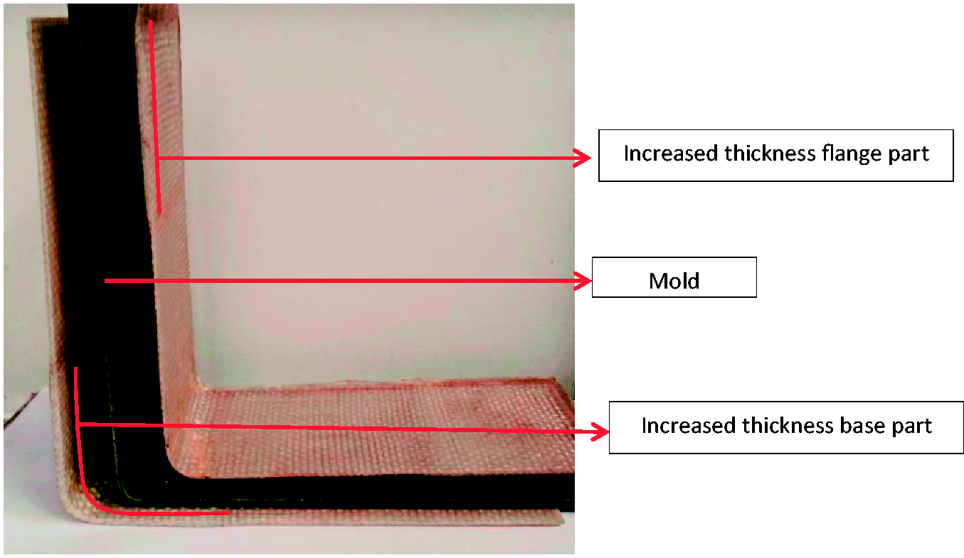
Design of experiment for different composite parts is given in Table 1. Parts with uniform thickness (4, 8, and 12 layers) are controlled samples having average thickness equal to 2, 3.35, and 4.72 mm, respectively. Effect of angle and effect of variable thickness at different angles is studied by comparing of four-layered composite parts at angles 45°, 90°, and 135° with varying thickness corner part of each angle. Z-shaped molds with same dimensions were used to study the effect of concave and convex tooling used in parallel. Uniform thickness Z-shaped composite part (four layers) was compared with part with increased corner thickness at two folding points (eight layers) composite parts to study the varying thickness effect in Z-shaped parts. Four layers Z-shaped composite was fabricated as control sample and increased thickness at corner (of concave 90° and convex 90°) were four-layer Z composites variables.
For measurement of spring-in angle microscope 800× was used to measure the inner angle accurately using Scope Image Plus software. Warpage consideration is not possible while using common digital angle meters (normally employed). Error/variation chances are more in angle measurements manually/by mechanical tools due to slippage and tightness variation. In case of thin composite parts, tightness can vary the original reading. Scope image software translates the angle enclosed in the picture of the geometry captured by high resolution camera (non-contact type testing method).
Figure 1 describes the terms used in deformation measurement. Warpage curve distribution across the whole flange length was measured by using spherometer. Three-leg spherometer (with distance between legs to be 50 mm) was moved on the flange, and the curvature of flange through its radius was analyzed. Scanning electron microscopy (SEM) and electronic microscopic images were taken to find out the gradient of resin fraction to explain the warpage produced. “250 Quanta electronic SEM” was used for analyzing cross-section of it under high energy electrons bombarded by tungsten filament. Sample of 5 mm square was cut and was placed under SEM after polishing with fine emery paper. Variations in distance of layers through thickness were measured. Same type of samples was placed under digital microscope having resolution of 800×.
Base spring-in is the angle distortion at base. It is measured at the starting portion of folding angle. Warpage is contribution to angle distortion due to curving of flange. Angle between flange tip and base has combined effect of both warpage and base spring so called base spring-in and warpage. A sample with base distortion of 2° and combined warpage and base distortion of 5° has warpage of 3°, i.e. angle of part is reduced by 3° due to warpage only.
Results and discussion
Effect of thickness
Deformation angles; spring-in angle (a) Effect of thickness, (b) effect of flange thickness increase, (c) effect of corner thickness increase, and (d) combined effect of flange and corner thickness increase.


Four-layered composite may be assumed as thin laminate (2.0-mm thick), the warpage in it is significant as defined in classical laminate theory. But as thickness increases, composite become thick and mechanics does not remain same. Warpage is reduced exponentially as compared with base distortion on increase of thickness, because top and bottom gradient difference is balanced by middle layers. At higher thickness, more dominating would be the effect of central average resin distribution of part thus reducing the warpage.
Effect of flange thickness variation.
Increased thicknesses at flanges parts relative to (controlled) uniform thickness parts have reduced distortions as shown in Figure 4(b). Distortion of increased thickness flange part is 1–3% more than average distortion of uniform thickness parts of its extremes. Major contribution to reduction in distortion is by the warpage reduction. Controlled samples have 220–250% more warpage than increased thickness at flanges parts. Base spring is same for both the increased thickness flange and controlled samples, but overall θbw is reduced up to 27% and 37% in increased flange thickness four- and eight-layer parts, respectively. Using equations (2) and (3) distortions of samples can be approximated and percentage reduction or average of extremes mentioned above will give the value of distortion for increased thickness at flange part. Higher the thickness difference, higher would be the effectiveness with respect to distortion reduction.
Warpage is somewhat contributed by flange thinning, but flange thickening has inverse effect on the warpage of the composite part. As thickness at base is same as that of controlled sample, so deformation at base is same as that of controlled samples. As shown in Figure 5 that, while shifting from eight to four layers, a resin zone is formed due to poor drape of continuous layers (at ending of eight layer/short increased thickness portion). Top triangular resin region cancels the effect of warpage or bottom resin rich region and thus makes the composite part to be straight. Moving spherometer on flange shows that there is straightness/convexness at point of shift from 4 to 8 or 8 to 12 layers within a part.
Microscopic images of Resin rich zones formed while shifting from eight to four layers within a composite part with micrometer reference scale.
Effect of base thickness variation.
Deformation behavior of increased thickness at base and controlled samples is given in Figure 4(c). Deformation of variable thickness parts is little bit (1–3%) less than average of two uniform thickness extreme parts. There is 40% to 37% reduced deformation in increased thickness part having thickness variation of four and eight layers, respectively.
In comparison with flange thickness variation, thickness variation at base is found to be more effective. Corner or folding point has major contribution in spring-in, so corner spring-in is reasonably reduced in thicker corner part. Mechanics of deformation in thicker portion (base) is altered and more deformation resistance is shown with higher thickness at base in comparison with uniform thickness part. Resin rich zone at shift of thickness variation play its part in reduction of distortions as explained in variable thickness flange part.
Effect of varying thickness at base and flanges combined.
Synergetic effect of corner and flange thickness variation was observed when both effect in combination. Increased thickness at base and flanges have (3–8%) reduced distortion than average distortion of uniform thickness of lower and upper extreme parts. Results shown in Figure 4(d) reveal that deformations in increased thickness base and flanges part have 46% and 69% reduced deformation as compared to uniform thickness four and eight layer composite part, respectively.
Both variations (base and flange thickness increase) are not impeding the effect of each other and are playing their role in parallel in deformation reduction, resulting in reasonable reduction of deformation.
Effect of different angles and increased corner thickness at different angles
Behavior of spring-in is very different for different tool angles. There is inverse relation of tool angle and distortions. Higher the folding angle, lesser will be the distortions induced in part. Increased corner thickness at sharp angles like 45°, further increases the deformation as compared to control samples as shown in Figure 6(a) and (b). Increased thickness corner at higher angles like 90° and 135° composites reduces deformations reasonably. Higher the mold angle, higher would be the effectiveness of increased thickness in reduction of distortion. In a sharp angle part, chances of presence of resin distribution gradient are higher [11,12]. Gradients become more pronounced at higher thickness in sharper angle part; hence the warpage (and overall distortion) is further increased.
(a) Comparison of θbw for uniform and varying thickness parts at different angles; (b) comparison of 
Effect of tooling and increased thickness corner in concave and convex tooling used parallel
Results shown in Figure 6(c) for Z-shaped composites show that concave and convex tooling used in parallel has completely different behavior than separately measured deformations. Normally, concave part has higher deformation in form of spring-in (due to resin accumulation in corner), but in parallel part, convex part showed higher deformation in form of spring forwardness. In case of varying thickness for a concave part, increased thickness increases spring-in and, in convex portion, there is a reduced distortion.
Deformation behavior of concave and convex tooling in parallel is very different from the parts manufactured separately. Leg joining concave and convex part has combined effect of both concave and convex tooling. There is resin flow from the top (folding corner) portion of convex tooling and that is relatively weaker than concave part, and concave part induces spring forwardness in convex part. Convex portion of Z part show spring forwardness and part moves away from tool instead of spring-in like 90 4-4-4 part.
In case of variable thickness at base resin rich zones (formed at shift from eight to four layers as shown in Figure 5) are at upper side and tend to increase spring-in of concave part. Furthermore, resin accumulation at base is also increased thus increasing spring-in. In case of convex portion of variable thickness Z part, there is reduced spring forwardness, as increased thickness at folding corner of convex tooling improves the stability/mechanical properties of convex part.
Scanning electron microscope (SEM) analysis
Low viscosity resins like vinyl-ester resin induce higher resin amount gradients in through thickness direction of the composite thereby dominating warpage factor. Resin gradients are measured and analyzed in 12-layer composite part using SEM (Figure 7(a) and (b)) and microscopic analysis (Figure 7(c)). Distance between the fabric layers at bottom showing higher resin volume fraction (having 427 and 538 µm) as shown in Figure 7(a) and (c). At top, there is higher fiber volume fraction and distance between plies is reduced to 307 µm as shown in Figure 7(b) and (c). Average distance of two extremes is found in middle plies, i.e. having 358–364 µm distance. Under action of gravity and external compressional pressure, the resin start accumulating at bottom.
(a) Distance between bottom plies; (b) distance between top plies; (c) microscopic image showing resin volume fraction gradient.
Conclusion
Deformation behavior of angled parts is affected by thickness variation in a part. In uniform thickness parts, the relation in plies/thickness has linear relation with base distortion (
Increased thickness at corner is suitable in case of convex tooling; in concave tooling, increased thickness at corner further increases the resin accumulation at corner and thus it has increased distortion. While using concave and convex part in parallel (as it is Z shape), concave portion induces higher distortions in convex portion. Varying thickness at base in Z shape increases the distortions of concave part while it stabilizes the convex portion and thus shows reduced distortions. Distortions in varying thickness at base Z part are relatively increased with respect to uniform thickness parts.
Distortions at higher angles are less than a sharper angle part. Sharper angle induces higher volume fraction gradient and hence higher warpage and corresponding distortion. Variable base thickness increase at sharper angle further increases the distortion, e.g. for 45° part. In larger angle parts, increase in corner thickness reduces the distortions. Higher the angle, higher is the effectiveness of increased variable thickness, e.g. 90° and 135° distortion is reasonably less in varying thickness part as compared to uniform thickness part.
Footnotes
Declaration of Conflicting Interests
The author(s) declared no potential conflicts of interest with respect to the research, authorship, and/or publication of this article.
Funding
The author(s) disclosed receipt of the following financial support for the research, authorship, and/or publication of this article: Authors are thankful to Higher Education Commission (HEC) of Pakistan for financial support to conduct this research work.