
Abstract
Multi-ply woven fabric consists of many layers and can be used to form three-dimensional shapes, which finds its application in a variety of end-uses. One of the advantages is that this type of products requires no seams or cuts. This paper presents a novel method to facilitate the design of 3D rectangular box-shaped fabrics made of multi-ply weaves. A preliminary folding-down process is a must for fabric manufacture and two folding approaches were developed accordingly. Approach A has been found to be more suitable for boxes with X ≥ 2Z. The elimination of quadruple-layer fabric region simplifies the design and weaving process. In this regard, plain weave was used sections form box body and basket weave was employed for bound-layer regions so that fabric recoiling could be avoided. The diagonal lines connecting the bound-layer and double-layer regions is required to have an angle of 45°, and hence a Jaquard loom was in use for manufacturing. As the fabric is formed by different parts, thread density varies, leading to uneven yarn tension. This problem can be solved using additional warp beams. Approach B requires the two side planes to be folded in, the design process of which is similar to that of approach A. Theoretically, boxes with multiple cells could also be designed using this technique. Approach A has been found to be able to deal with boxes of various geometrical parameters. One problem of the 3D fabric is the soft edges, which requires further investigations.
Introduction
3D woven fabric is a single-fabric system with constituent yarns disposed in three mutually perpendicular planes [1,2]. According to Chen et al. [2], 3D fabric is classified into four categories: solid, hollow, shell and nodal, all of which can be conveniently manufactured on conventional 2D looms with or without modifications. In addition, the development of 3D weaving machines [3–11] serves to increase the production and widen the variety, aiming to meet with economic and technique challenges in industry, such as composite engineering. The benefits of textile composites have been greatly recognised for their lightweight and good mechanical properties. Their applications have penetrated into many fields, e.g. military engineering, aerospace and sports equipment. For solid fabric such as orthogonal weaves, a widely recognised advantage over 2D fabric is its better de-lamination resistant properties [12–14]. As high performance fibre is the main load-carrying constituent for a fibre-reinforced composite, its mechanical properties is greatly dependent on load path. Nevertheless, the subjection of out-of-plane load is inevitable, and the force will ultimately be transferred through a joint to the adjacent layers. The joint for a layup 2D textile composite is essentially resin, which is far weaker than fibre. In a 3D structure, yarns could be inserted in the through-the-thickness direction and the resin joint is reinforced by high performance fibre, and hence the mechanical performance is improved.
Another advantage for 3D fabric is the elimination of weak point in the whole system. The conventional approach to design a 3D shape for composite perform or other end-uses is using cut-and-sew technique. 2D fabrics are manufactured on power looms and cut into stripes. A sewing machine is needed to connect different parts. This technique is widely accepted for the manufacture of composite helmet. The disadvantage is self-evident, e.g. sewing damage the continuity of the system, leaving weakness lines between the adjacent stripes. An improvement is to use easy-mouldable 3D angle-interlock fabric as reinforcing material to eliminate the weakness lines [15,16]. An alternative is to create a dome-shaped fabric by weaving fabric with different float length [17]. This is because fabric sections made from short float tend to expand, whereas the short float part would shrink when taken off the loom. Dome-shaped fabric could also be formed by modifying take-up and let-off mechanisms. In this regard, a triangular-fan-reed is required to facilitate the weaving process [18].
For multi-ply weaves, seamless three-dimensional systems could be formed by creating non-stitching parts. The simplest type is nodal fabric, which is essentially a double-layer structure with hollow and non-hollow regions. The hollow region could be pulled into shapes, forming a network of tubular members. It has been reported that fabric starts to wrinkle intensively at nodal joints [19]. This is because inflating the hollow zones leads to a decrease in width. Improvement has been made to solve this problem by additional weft insertions, and the modified machine was presented at Techtextil 2015 [20]. In addition, an algorithm has been developed for nodal fabric design, which includes structural specification, structure flattening, pattern segmentation, weave assignment and weave combination [21,22]. The complicated hollow structure is divided into two types, i.e. one with flat surfaces and one with uneven surfaces [2]. For the former case, top and bottom layers are connected by additional middle layers, the length of which is determined by fabric cross section. The cross sections could be trapezoidal, triangular [23], rectangular [24] and double-ribs [25]. For the latter case, the middle layers are combined and separated at predetermined intervals, constituting arrays of hexagonal cells. The design and manufacturing process of this cellular structure has been put into publication by Chen et al. [26,27], who also systematically studied the influence of such structural parameters as opening angle, the length of free wall and bond wall on the energy absorption properties of cellular fabric-reinforced composite [28,29].
Chen and Tsai [30] further developed the application of multi-ply fabric on seamless box shell based on origami (paper-folding) principle. For a given shape, it is usually folded down in such a way that the geometry is weaveable on a power loom. The folded fabric is divided into different multi-ply regions both lengthwise and widthwise to satisfy the structural requirement. When taken off the loom, the fabric could be opened up to form predetermined 3D shapes. In this paper, an alternative designing approach of 3D seamless box-shaped fabric will be presented using multi-layer weaves. This approach is adaptable for rectangular boxes of any geometrical parameter. In addition, the same technique could also be employed to design multi-cell boxes, aiming to explore the potential of 3D fabric in design engineering.
Paper-folding approaches
3D fabrics could be manufactured by weaving, knitting and braiding, among which weaving enables the products to have high dimensional stability, and hence the mechanical properties of single fibres could be exhibited. Composites reinforced by this type of fabric are more damage resistant than others. For the manufacture of 3D box-shaped fabrics, multi-ply weaves should be designed in such a way that rectangular box of various shapes could be properly formed after taken off the loom and pushed open. In this research, two paper-folding approaches were studied and compared for their suitability for weave design.
Approach A: Rectangular box-shaped weaves with bottom plane folded
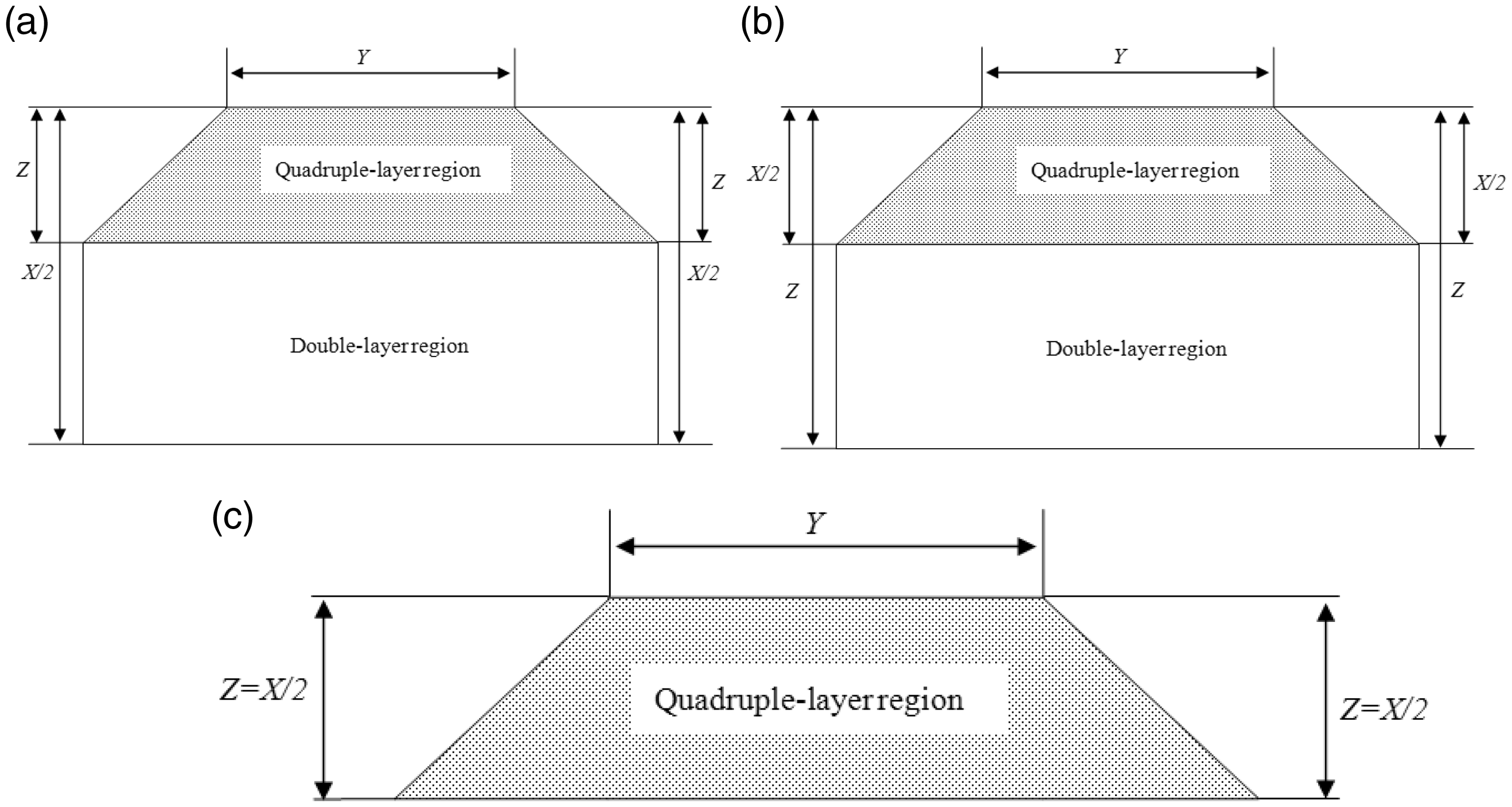
Imagine a box without lid has three sides, which is shown in Figure 1. The height is denoted by Z, and the longer and shorter bottom sides by X and Y, respectively. With X–Y plane folded along the longer bottom side X, three cases need to be considered. When the value of X is more than twice that of Z (X > 2Z), the folded weave could be divided into two regions: quadruple-layer region and double-layer region (Figure 2(a)), and hence the weave could be designed thereof; when X < 2Z, the top section is made of a quadruple layer weave and the bottom section is made of a double layer weave (Figure 2(b)); when X = 2Z, the whole trapezoid area is formed by quadruple-layer fabric (Figure 2(c)). For the case of X ≥ 2Z, the weave design could be further simplified by unfolding the fabrics, in which case the weave is only formed by single-layer and double-layer regions. Details will be presented in next section. If the X–Y plane is folded in along the short bottom side Y, the situations are similar.
Unfolded paper box. Schematic diagrams of box with top plane folded in for the case of (a) X > 2Z, (b) X < 2Z, (c) X = 2Z.
Approach B: Rectangular box-shaped weaves with side planes folded
The second approach involves folding the two side-planes of Z-Y. As can be seen in Figure 3, the weave is formed by quadruple-layer and double-layer regions. The shape of the two regions is determined by the values of X, Y and Z. It is not difficult to imagine that when X = Y, the weave is covered by quadruple-layer fabric only. For the case of X ≥ 2Z, approach A is more convenient to facilitate the weaving process. For the case of X < 2Z, the weaving processes for the two types of folding principles are similar. In addition, if the box is designed with lid, the two aforementioned approaches are identical.
Schematic diagram of box with side planes folded.
Weave design and manufacture
Weave design for rectangular box-shaped fabrics in the case of X ≥ 2Z
Approach A depicted in Figure 2 was employed for the box-shaped weaves design for the case of X ≥ 2Z and the folding process can be further simplified. As it can be seen in Figure 4, the fabric could be divided into bound-layer, double-layer and false double-layer region. In the double-layer region, there are two layers of fabric. The two separate single layers are connected into one to form a bound-layer region. In the false double-layer region, the upper layer is formed by weft yarns only. The bottom layer has the same structure as that in the double-layer region. When taken off the loom, both the bound-layer region and the weft yarn region will be cut off so that box could be opened. For the case of X = 2Z, the false double-layer region would be eliminated, other parts being equal. After fabric formation, the upper layer of the fabric will be cut along the central line. In order to retain the rectangular dimension, the diagonal lines connecting the double-layer and bound-layer region are required to have an angle of 45°.
Schematic diagram of folded box for the cases of (a) X > 2Z and (b) X = 2Z.
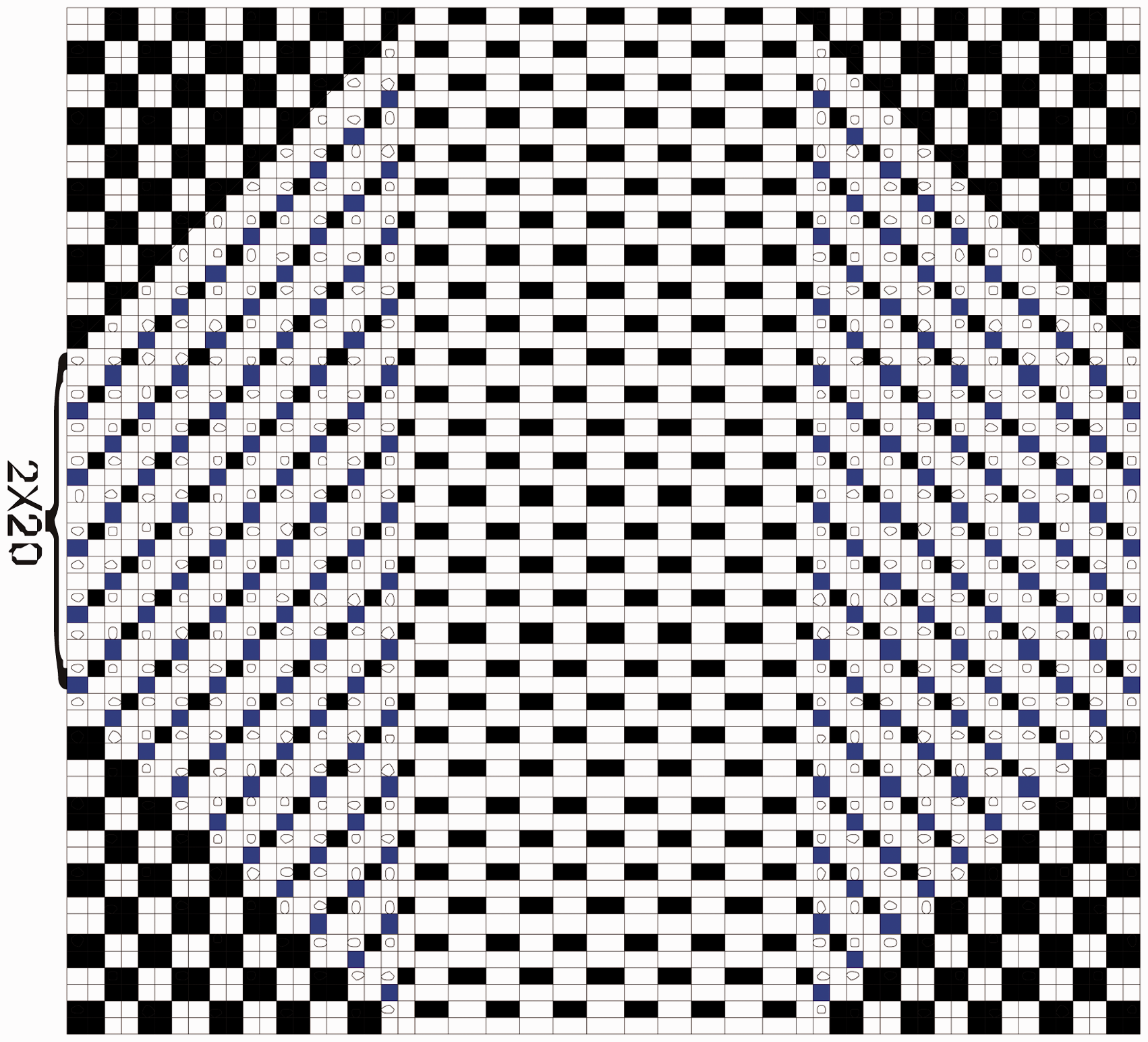
An example of box-weaving is illustrated: a box is 1.5 cm in length, 1 cm in width, and 0.5 cm in height. The warp and weft density (Pj and Pw) of the single layer is 20 threads/cm and the plain weave was in use. To avoid the potential danger of fabric, basket weave (Figure 5) is in use for the bound-fabric region so that the shrinkage of the whole fabric is kept similar. When X ≥ Y and X > 2Z, the weave design is undertaken as follows:
The numbers of the warp and weft yarns are listed in
Table 1
.
Reeding plan:
For the double-layer region, a reed plan of four threads per dent was adopted; For the false double-layer region, a reed plan of two threads per dent was in use. The number of weft and warp yarns in a box for the case of X > 2Z. Weave diagram for the case of X > 2Z. Weave diagram: The weave diagram is shown in Figure 5. The blocks in the middle have different size compared to those on the sides, indicating the lower warp density of false double-layer region.

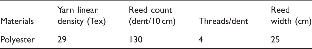
Weave manufacture for rectangular box-shaped fabrics for the case of X ≥ 2Z
Parameters for rectangular box-shaped fabric production.

Rectangular box-shaped woven fabric.
Tensile test on the strength of the diagonal lines
Tensile tests have been undertaken to evaluate the strength of the 45°diagonal line, which connects the bound-layer and double-layer regions. Figure 7 shows the testing scheme. The machine in use was Instron 5582 and the specimen on the machine is extended at a constant rate (250 mm/min) and the measuring mechanism moved a negligible distance with increasing load. The results were compared with those in single-layer region, which are shown in Table 3. It can be seen that both the strength and breaking energy exhibit similar values for the two cases, indicating that the connection line does not weaken the properties of the box when subjected to load.
Schematic diagram of load direction on fabric strips with 45° diagonal line. Tensile properties of the fabric in connection line and single-layer region.

Design and manufacture for rectangular box-shaped fabric on the case of X < 2Z
For box with X < 2Z, approach B was used for explanation. It can be seen in Figure 8 that the fabric also comprises three regions, i.e. bound-layer region, double-layer region and quadruple-layer region. A weaveable structure could be achieved by folding the height inside the box, forming 45° diagonal edges.
Schematic diagram of folded box for the case of (a) X < 2Z using approach B.
An example of box-weaving is illustrated: a box is 1.5 cm in length, 1 cm in width and 1 cm in height. Yarn in use is 29 Tex for both of the weft and warp directions. The thread density of the single layer is 20 threads/cm (Pj and Pw) and a plain structure was employed. Basket weave is employed for the bound-layer region. Fabric pattern could be designed as follows:
The numbers of the warp and weft yarns are listed in
Table 4
.
Reed plan: Reed plans of four threads per dent and eight threads per dent were adopted for double-layer region and quadruple-layer region, respectively. Weave diagram: The weave diagram is shown in Figure 9. The number of weft and warp yarns in a box for the case of X < 2Z. Weave diagram for the case of X < 2Z.


Problems and solutions during the manufacturing process
It has been found during the manufacturing process that, apart from developing weave diagrams, the key to achieve the 45° diagonal edges is the proper control of thread density. This is because the formation of the 45° diagonal lines in the vicinity of the four edges is essential for box shape. If the ratio of warp/weft thread density is 1:1, the line could be achieved by using a weft–warp conversion ratio of 1:1; if the ratio is not 1:1, the conversion process could be adjusted correspondingly. In addition, it is difficult to achieve the aforementioned diagonal lines using cam and dobby shedding mechanism. Although little modification is required on the loom, jacquard shedding mechanism is a must to manufacture 3D rectangular box-shaped fabrics.
Another problem worth mentioning is the uneven tension caused by different thread density in the single-layer and double-layer regions. The existence of different region results in inconsistent shrinkage rate. These two factors combine to cause an irregular surface of the fabric. The solution is to control warp tension by using multiple warp beams.
Rectangular box-shaped fabric with cells
Since paper-folding principles were used to manufacture some basic 3D rectangular box-shaped fabrics, it follows that more complicated types could be developed as well. In this section, the possibility of designing boxes with cells will be explored using the same technique. Figure 10 shows a rectangular box sectioned into two cells, in which X1 = X2 = X/2. As the two cells share the same wall, the top central part of the trapezoid geometry is formed by seven-layers of fabric when the box is folded down using approach A (Figure 11(a)). The number of layers in the other two regions is doubled due to the additional cell. It is not difficult to work out the weave design for box with n separated cells. By using approach B, the paper is divided into four regions, and hence the weaving process becomes more difficult compared to the former situation (Figure 11(b)). In addition, when Y < X1, X2 and the box has to be folded along X, it is not possible to use approach B. This is because if the shared wall is fixed in a double-cell box, the shorter and longer sides in the individual cells are not reversible as that in a single-cell box. On the other hand, this problem does not exist in approach A, where the box is foldable regardless of its dimensional parameters. A more complicated case is that X1≠X2, which means cells have different sizes. In this regard, approach A could still be applied and the width of the bottom rectangular regions are determined by the values of X1 and X2. If Z≤X1/2 and Z≤X2/2, the top trapezoid regions are identical and the bottom rectangular regions are different in width (Figure 12(a)). If any of X1/2 or X2/2 is shorter than Z, both of the trapezoid and the rectangular regions exhibit different shapes. In addition, approach B could also be used under the condition that Y ≥ X1 and Y ≥ X2. The difference is that the heights of the trapezoid regions are not identical (Figure 12(b)). In both cases, it is necessary that the diagonal lines of the trapezoid region for different cells are kept 45°, so that the 3D geometry could be properly formed.
Box with cells of equal size. The geometry of folded box using (a) approach A and (b) approach B. Schematic diagrams of folded double-cell box using (a) approach A and (b) approach B.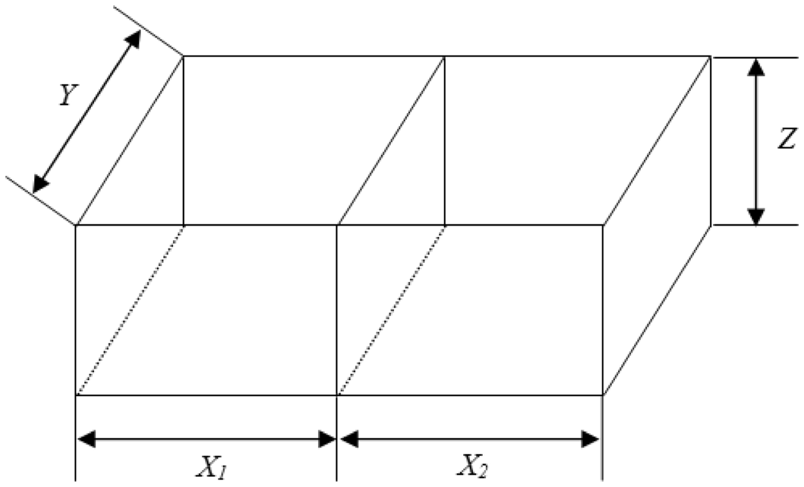


Conclusions
There has been increasing attention paid to the potential of multi-ply fabric in industrial application due to its through-the-thickness properties and 3D geometry.
In this paper, 3D rectangular box-shaped fabrics were created using weaving techniques. For this type of weave, a preliminary folding-down process is required for the fabrication process. Two folding approaches were developed, i.e. box folded on the bottom plane and on the side planes. For the cases of X ≥ 2Z, the application of former approach is determined to better facilitate the design and manufacture process due to the fact that the layers of fabric could be reduced. If the plain weave is in use for single-layer and double-layer regions, then the basket weave is employed for the bound-layer region to avoid fabric recoiling. The resultant weave was produced on a Jaquard loom. The diagonal lines connecting the bond-layer and double-layer region were tested for its strength and the values were found to be similar as those of single-layer region. For the cases of X < 2Z, approach B was in use and the weave diagram was developed accordingly. The formation of 45° diagonal lines could be achieved by using Jaquard shedding system, and the uneven yarn tension due to difference weave density can be solved using multiple warp beams. In addition, the aforementioned approaches could also be applied for multi-cell boxes. Nevertheless, approach A has been found to be able to deal with boxes of various geometrical parameters. One problem worth noting is the soft edges in the resultant fabric. Additional work is under way to solve this problem by using stiff fibres, aiming to provide a desirable 3D preform for composite manufacture.
Footnotes
Declaration of Conflicting Interests
The author(s) declared no potential conflicts of interest with respect to the research, authorship, and/or publication of this article.
Funding
The author(s) disclosed receipt of the following financial support for the research, authorship, and/or publication of this article: This research is funded by the National Natural Science Foundation of China (grant no. 11502179).