
Abstract
This paper presents an experimental investigation into the influence of bond characteristics between textile and matrix on the mechanical behavior of textile-reinforced concrete (TRC). Two types of tests were performed, i.e. pullout test and uniaxial tensile test. Self-compacting fine-grain concrete was adopted. Two kinds of hybrid textile, consisting of both carbon and E-glass yarns, were specially prepared for this study. The experimental results show that sticking sands on the textile after epoxy resin impregnation can improve the interfacial property between textile and matrix. The specimens with textile of 10 mm × 10 mm mesh have stronger bond strength than those with textile of 25 mm × 25 mm mesh, and can reach the maximum tensile strength of yarns when the initial bond length is between 30 mm and 35 mm. Moreover, sticking sands on the textile can improve the multiple cracks form and the ultimate bearing capacity of TRC under uniaxial tensile load. Specimens with textile of 10 mm × 10 mm mesh have higher first-crack loads than those with textile of 25 mm × 25 mm mesh whether or not the textile surface treatment was conducted, and also have better crack distribution. Finally, based on the experimental results from TRC under uniaxial tensile load, a double linear constitutive equation of stress–strain relationship of carbon fiber yarn is provided in this paper.
Keywords
Introduction
Textile-reinforced concrete (TRC) is increasingly popular in structural applications [1–9]. It is a composite material consisting of fine-grain concrete and multi-axial textile reinforcement. By using corrosion-free fibers such as alkali-resistant glass (AR-glass) fiber, carbon fiber, aramid fiber, and basalt fiber, TRC possesses superior durability [1,5–8]. Furthermore, the high strength fiber along the main stress direction of TRC makes this composite have high effectiveness in strengthening of plain concrete members [1,5–8]. To ensure the performance, the mechanical behaviors of TRC have been investigated. Besides the properties of fiber and matrix themselves, the mechanical behavior of TRC members is also significantly associated with the interface bond characteristics between fiber and matrix, which is influenced by fabric geometry, knitting type, mesh size and fiber type, textile surface treatment methods, and matrix properties. Jesse et al. [1] summarized major factors which influence the load-bearing capability of TRC, including reinforcing ratio, fabric filament damage during production, fabric reinforcing direction, and interface bond characteristics between textile and matrix. Peled et al. [2,3,9,10] investigated the effect of fabric geometry on the bonding performance and reinforcing effectiveness of TRC. It was discovered that the type of knitting (or weaving) had important influence on the interfacial bond strength.
To obtain a complete interfacial bond characterization between matrix and fiber, many researchers have performed a lot of experiments. Colombo et al. [11] presented experimental investigation of TRC on tensile tests, considering the influence of reinforcement ratio, fabric geometry, curing conditions, displacement rate, and specimen size. Cevallos and Olivito [12] studied the effects of the fiber type, fabric geometry, physical and mechanical properties of fabrics and the volume fraction of fibers on the tensile stress–strain response and crack propagation of cementitious composites reinforced with natural fabrics. It was found that the fabric geometry and the volume fraction of fiber were the parameters that have the greatest effects on the tensile behavior of these composite systems. Mumenya et al. [13] conducted uniaxial tensile testing on weathered textile concrete samples to analyze the multiple cracking patterns. Peled et al. [14] used closed-loop uniaxial tensile tests to study the tensile behavior of pultruded cement composites with various fabric types. It was found that hybrid composite made of PE and AR glass sustained strains better than 100% AR glass composite, and was stronger than single PE fabric composite. Larrinaga et al. [15] investigated the experimental and numerical modeling of basalt textile reinforced mortar to deepen the knowledge of this composite material in terms of tensile behavior. Santis and Felice [16] presented an experimental study on the tensile behavior of strengthening systems comprising two different textiles and five mortar matrices.
The above results were almost all coming from the TRC with not being polymer-impregnated textile. This research makes a further contribution to the existing knowledge regarding TRC and the influence of textile’s bond characteristics on mechanical behavior of self-compacting concrete reinforced with hybrid textile is investigated. In this test, self-compacting fine-grain concrete was adopted for TRC. Two kinds of hybrid textiles, consisting of carbon and E-glass yarns, were produced specifically for this work. Two tests were adopted to evaluate the influence of textile surface treatment and textile mesh size on the bond characteristics and mechanical behavior of TRC. The interfacial bond between the hybrid fabrics and the self-compacting fine grain concrete was investigated to offer the necessary parameters for engineering.
Materials and methods
Textile reinforcement
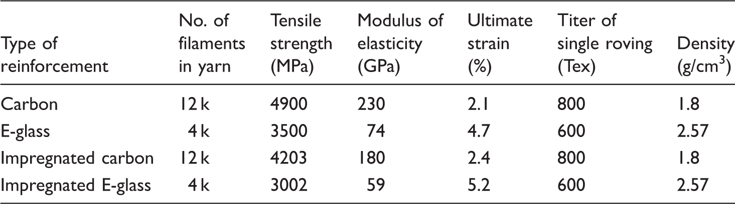
One particular type of hybrid textile made of carbon and E-glass yarns was used as textile reinforcement in all specimens. The weft thread was torayca carbon yarns and the warp thread was E-glass. The two sets of perpendicular yarns were connected tightly together with stitches. E-glass fiber cannot withstand alkaline conditions in concrete for a long time and, therefore, its load-carrying contribution was not considered in this study. It was used only to fix the carbon fiber. In addition, the textile was impregnated with epoxy resin, and the alkali-resistance of the E-glass fiber could be improved. The mesh sizes of textile were 25 mm × 25 mm and 10 mm × 10 mm, as shown in Figure 1. The mesh sizes of 25 × 25 and 10 × 10 have great difference in mesh spacing, which is beneficial in reflecting the influence of mesh sizes on TRC. It highlights the influence of geometry of textile on the mechanical properties of TRC. The knitting equipment was German double axial direction warp-knitted machine P2-2 S. The details of hybrid fabric according to the manufacturer are listed in Table 1. Epoxy resin impregnation of textile was adopted before it was embedded in concrete. Mechanical properties of the impregnated yarns was calculated and presented in Table 1. Due to the influence of epoxy resin impregnating, the measured elastic modulus of yarns was lower than that provided by the manufacturer, but the ultimate elongation was higher.
Geometry of hybrid textile: (a) 25 mm × 25 mm textile; (b) 10 mm × 10 mm textile. Properties parameters of hybrid fabric.
Fine-grain concrete matrix
Mixture and proportion of fine-grain concrete.

Specimens
The wood mold with dimensions of 900 mm × 900 mm × 10 mm was used. The concrete of the thickness of 5 mm was placed into the mold, and then the textile fabric was carefully fixed on it. After that, a layer of concrete, whose thickness was also 5 mm was placed. The carbon roving should be placed paralleling to the edges of specimens without any damage. The plates were demolded and removed into curing room with 20℃ and 95% RH after 1 day. Then the plates were cut by a saw to all specimens for the tests after 56 days curing. In this study, two types of tests, i.e. pullout test and uniaxial tension test were adopted to evaluate the influences of variables, i.e. textile surface treatment and textile mesh size. There is no standard test method so far and, thus, the tests conducted in this paper are according to various studies: the yarn pullout tests are according to the works of Banholzer [4], Xu et al. [8], and Natalie [18] and the tensile tests are according to studies of Hegger et al. [5] Colombo et al. [11] Cevallos and Olivito [12], and Larrinaga et al. [15].
Yarn pullout test
In order to get a better understanding of crack-bridging mechanism, rectangular specimens (160 mm long, 70 mm wide. and 10 mm thick) were cut from the lager plates produced before. Each configuration had five specimens. The initial bond length was determined by specific arrangement of “must” crack-positions visible as saw cut on both sides, as shown in Figure 2. In the notched cross section, only one multifilament-yarn was still intact and connected the two parts of the plates to each other. Four metal plates were pasted on both ends of specimens with structure adhesive and connected to machine through bolt. An electro-hydraulic testing machine with the maximum capacity of 30 t was used. The displacement control loading mode was adopted. The rate of cross-head displacement was at 1.0 mm/min. In this test, the influence of sticking sands on TRC is reflected by the textile with the mesh size of 10 × 10. The textile with the mesh size of 25 × 25 is mainly used to study the influence of the mesh size of textile on the bonding properties of TRC. The details of specimens for yarn pullout test were summarized in Table 3.
Schematic of test set-up for pullout test: (a) specimen dimension and loading set up; (b) demonstration of specimen at half of clamping device. Details for specimens of pullout test.

Uniaxial tensile test
In tension test, rectangular plates (380 mm long, 60 mm wide, and 10 mm thick) were cut out from the lager plates as the same as those for yarn pullout test. Each configuration had three specimens. The total length of specimens is 380 mm and the measured range is 200 mm, as shown in Figure. 3. Four metal plates were pasted on both ends of specimens with structure adhesive and connected to machine through bolt. Two LVDTs were used to measure the elongation displacement. Specimens were loaded using an electro-hydraulic test machine with the maximum capacity of 100 t. Displacement-controlling loading mode was adopted and the loading rate of was 0.1 mm/min.
Schematic test set-up for tension test: (a) loading set up; (b) specimen dimension (mm).
Experimental results and discussion
Yarn pullout test


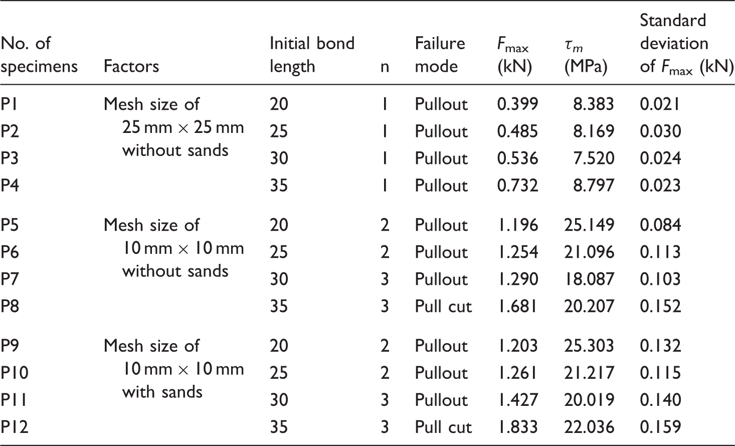
The average value of maximum load and interface bond strength.
Influences of initial bond length on bond
In order to identify the minimum embedded length of textile in matrix, specimens with different initial bond length, as listed in Table 3, were tested. Figure 4 shows the average pullout load–slip curves of specimens obtained from the pullout test. According to the results from Table 4 and Figure 4, it is can be seen that different carbon yarns have different bond property with fine-grain concrete. During the process of carbon fiber yarns’ pullout, the yarn near the loading end debonds first, and then there are only the frictional resistance force and the mechanical interaction force in this interface. As the load increases, debonding will develop to the deep of specimens. When the yarn at free end debonds, the debonding area will expand to the entire interface, and then the fiber yarn is pulled out gradually. These have been also found in Li and Xu [7] and Natalie et al. [18]. In Figure 4(a), it can also be seen that the peak pullout load increase with the increase in initial bond length and this phenomenon also can be found in Figure 4(b) and (c). Yarns of all specimens are pulled out in Figure 4(a); however, in Figure 4(b) and (c) the yarns of specimens’ initial bond length which is 35 mm are pulled cut. The results reveal that the textile with the mesh size of 25 mm × 25 mm has a poor interface bond compared to that of 10 mm × 10 mm (shown in Table 4). This is due to the effect of the warp E-glass yarn, and in the same embedded length of textile, the textile of 10 mm × 10 mm mesh size has more number of warp glass yarns, which is shown in Table 4. As a result, all specimens with the textile having mesh size of 25 mm × 25 mm fail in the pullout of textile, while specimens with the textile of 10 mm × 10 mm mesh size reach the maximum tensile strength of carbon yarn when the initial bond length is between 30 mm and 35 mm. It is believed that rupture failure was related to the embedment length of the fiber as well as the surface treatment of the textile [18].
Curves of pullout load–slip of specimens with different initial bond length: (a) results of specimens with textile of mesh size of 25 mm × 25 mm and without sand; (b) results of specimens with textile of mesh size of 10 mm × 10 mm and without sand; (c) results of specimens with textile of mesh size of 10 mm × 10 mm and with sand.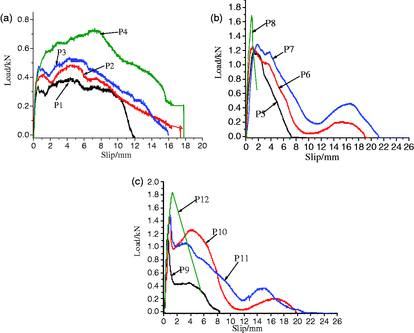
Influence of surface treatment of textile on bond
To study the influence of surface treatment of textile on the pullout behavior of textile in detail, the pullout load–slip curves of specimens with textile having the same embedded length but different surface treatment are shown in Figure 5(a) and (b). In Figure 5(b) it can be seen that the peak pullout load of specimen P11 is higher than specimen P7 and before the peak pullout load, the slope of specimen P11 is bigger than specimen P7; and this phenomenon also exist between specimen P9 and P5. This is because the average interface bonding strength of the textile impregnated by epoxy resin and covered with sands is higher (shown in Table 4). During the process of the pullout test of carbon fiber yarns without sand (see Figures 4 and 5), when the pullout load nears the peak value, there is a slight slip at the free end, but the chemical bond force is not completely lost. Therefore, when the slip increases, there exists a stage where the pullout load will remain unchanged or changes slightly. When it reaches the peak load, the interface force fully is provided by the frictional resistance force and the mechanical interaction force. Then the fiber yarn is pulled out gradually and its surface is smoothed slowly, and the mechanical interaction force reduces to zero and there is only frictional resistance force at this interface. However, during the process of the pullout test of carbon fiber yarns with sand, when the pullout load reaches the peak value, the load reduces quickly. That means the sand on the yarn have spalled partly, and the interface between the yarn and fine-grain concrete has been destroyed mostly. But the interface at the free end is not totally destroyed, so the pullout force will overcome the interface bond force further. Then the pullout load will have an increase or remain unchanged (the initial bond length of the carbon fiber yarn is relatively short) until there is great slip at free end. Since then the development of the process is similar to the fiber yarn without sand. Moreover, when the initial bond length is longer than 20 mm and the pullout force reduces to 0.2–0.3 kN, there is a improved process for the interface bond between the yarn with sand and fine-grain concrete. This might be due to the carbon fiber yarn’s need to overcome the constrain force of E-glass fiber yarn at their joints position.
Curves of pullout load–slip of specimens with different surface treatment textile: (a) results of specimens whose initial bond length was 20 mm; (b) results of specimens whose initial bond length was 30 mm.
Influence of mesh size on bond
Figure 6 shows the curves of pullout load–slip for specimens with the same embedded length but different mesh sizes of textile. The peak pullout load and average interface bonding strength of specimen P5 is higher than those of specimen P1 in Figure 6(a), and the peak pullout load and average interface bonding strength of specimen P7 is higher than those of specimen P3 in Figure 6(b) (shown in Table 4). Therefore, the specimens with textile having the mesh size of 10 mm × 10 mm have better interfacial bond property than those with 25 mm × 25 mm textile. Moreover, the maximum slip of specimen P5 is smaller than that of specimen P1, but the maximum slip of specimen P7 is bigger than that of specimen P3 as seen in Figure 6(b). For specimens with textile having the mesh size of 10 mm × 10 mm, the interfacial force have a strengthened process while descending at some value when the initial bond length is longer than 20 mm, and this phenomenon can also be seen in Figure 4(b) and (c). It is seen that the main reasons are the ribbed surface formed by the binder threads and the change of the roving diameter over its length especially at the crossing points where the perpendicular woof roving is fixed. The binder threads are caused by the warp knitting process and fixed by the epoxy resin.
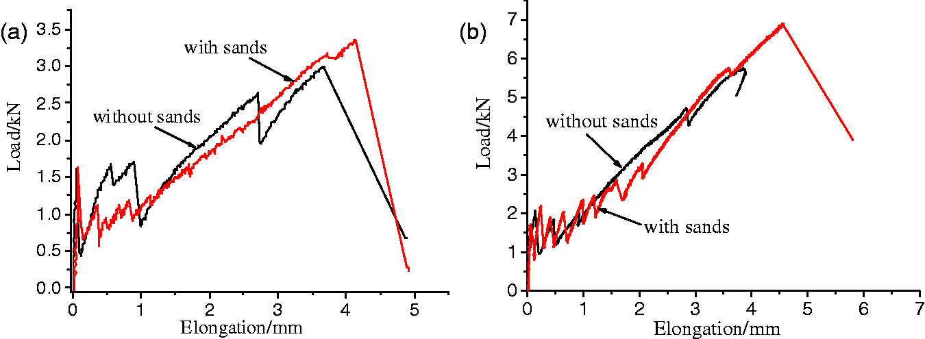
Curves of pullout load–slip of specimens with textile having different mesh sizes: (a) results of specimens whose initial bond length was 20 mm; (b) results of specimens whose initial bond length was 30 mm. Curves of tensile load–elongation of specimens of different surface treatment textile: (a) textile of 25 mm × 25 mm mesh size; (b) textile of 10 mm × 10 mm mesh size.
Tensile test
From Figures 7 and 8, three typical states can be distinguished [1,5,15]: state I is elastic stage, state II is multiple cracks stage, and state III is post-cracking after the ultimate deformation.
Curves of tensile load–elongation of specimens of different mesh size textiles: (a) specimens without sands; (b) specimens with sands.
The average value of first-crack load and ultimate load.

Influence of surface treatment of textile on TRC
In Figure 7, the results of load–elongation of specimens with different surface treatments of textile are illustrated. On the crack-free state I, the stiffness of both matrix and fibers determines the slope of curve [1,19]. When the tensile force exceeds the tensile ultimate strain of the matrix, the first crack appears. The first crack is defined as the first snap-back in the measured curve. It comes to the crack-formation state II. At this stage, tension behavior usually undergoes two processes [1,5], denoted with IIa and IIb, respectively. In stage IIa, because of the suppression of crack opening by the bridge action offered by textile reinforcement, additional multiple cracks were formed with the increased of applied load [1]. The slope of stress–strain curve started to reduce during multi-cracking process. After cracking had been finished, state IIb developed. In this stage, no further cracks took place and the textiles were stressed with an increasing load until their tensile strength was reached. Generally, state IIb is considered to be the final cracking state with the additional deformation [1,5]. Sticking sand has little influence on the value of first crack in both textile mesh sizes (shown in Table 5). However, it can be seen that specimens with textile covered with sand have more snap-back in curves at this state, which means these specimens having more cracks and better crack distribution, and absorb more energy. Sticking sand on textile improves the interface bonding property between textile and fine-grind concrete. When the first crack appeared, interface stress can be transferred effectively, and then the first crack develops slowly, with the increasing load, multiple cracks can be formed at other weak locations. Specimens of textile with sands as seen in Figure 7(a) and (b), have multiple cracks. The final state is the crack-widening state III. The obvious nonlinear deformation after peak load could not be observed in TRC because of the elastic-perfectly plastic behavior of reinforced fiber such as carbon fiber [1]. The existing cracks become wider until TRC fails. Textile and matrix carry load together until the ultimate force of composite is reached and tension ruptures of yarns occur. The ultimate loads of specimens with textile covered with sand are higher due to the improvement of interface bonding.
Influence of mesh size on TRC
The results of specimens with textile of different mesh size are presented in Figure 8. At the crack-free state, the length of this portion of the curve of the specimen with textile of 10 mm × 10 mm mesh size is longer, and the first-crack loads of specimens with textile of 10 mm × 10 mm mesh size are higher in both textile surface treatments (shown in Table 5). At the crack-formation state, the stiffness of TRC thin plate with textile of 10 mm × 10 mm mesh size is stronger and that can be also seen on crack-widening state in Figure 8(a) and (b). That means the interface bond of textile of 10 mm × 10 mm mesh size is stronger and, hence, the anti-crack ability of textile is made better exerted. Therefore, the crack width and crack spacing of the component with textile of 10 mm × 10 mm mesh are decreased, as is shown in Figure 9, resulting in making the concrete and the textile better bearing the load cooperatively. Thus, the ultimate loads of specimens with textile of 10 mm × 10 mm mesh size are higher in both textile surface treatments.
Crack patterns on specimens’ surfaces of different mesh size textiles: (a) textile of 25 mm × 25 mm mesh size; (b) textile of 10 mm × 10 mm mesh size.
Mechanical model of TRC under uniaxial tension
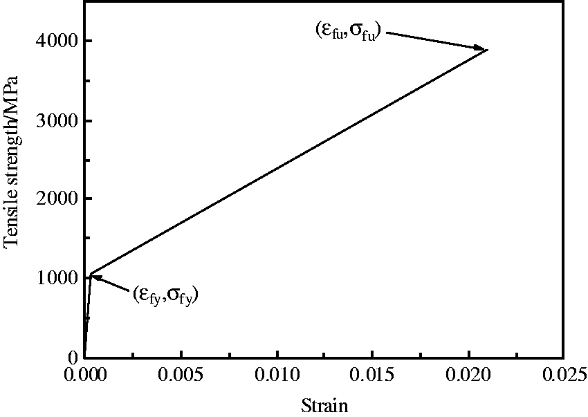
When the fine-grain concrete reaches its tensile strength at weak spot, the microcracks appear on the specimen. Due to the cohesion force of concrete, the tensile stress of concrete reduces to zero will need a process. During this process, due to bridge action offered by textile reinforcement, the development of microcracks is constrained, and more microcracks may appear in other places. When the concrete arrives at its ultimate tensile strain, a macroscopic crack will appear on the specimen and an obvious point of fluctuation will also appear on the load–displacement curve. The load at this macroscopic crack is totally carried by carbon fiber yarn; at this point the tensile strain ( Stress–strain relationship of carbon fiber yarn from uniaxial tensile tests of TRC thin-walled plates.

Types and experimental results for TRC specimens.

Conclusions
The following conclusions were drawn from the findings of the research:
Specimens with the textile of 10 mm × 10 mm mesh size can reach the maximum interface bond strength when the initial bond length is between 30 mm and 35 mm. However, specimens with the textile of 25 mm × 25 mm mesh size need longer bond length. Sticking sand on the textile can improve the interface bond strength between textile and matrix in both textile mesh size. Specimens with the textile having the mesh size of 10 mm × 10 mm have better interfacial bond property than those of the textile with 25 mm × 25 mm mesh. Sticking sand has little effect on the first-crack load of specimens under uniaxial tensile load; however, it is beneficial to the multiple cracks form and improves the ultimate bearing capacity of TRC thin plate. Specimens with textile of 10 mm × 10 mm mesh have higher first-crack loads than those with textile of 25 mm × 25 mm mesh whether or not the textile surface treatment was conducted, and also have better crack distribution. The double linear constitutive equation described the stress–strain relationship of carbon fiber yarn fits well, but still needs to be validated before being applied to engineering.
Footnotes
Acknowledgements
The experimental work described in this paper was conducted at the Jiangsu Key Laboratory of Environmental Impact and Structural Safety in Civil Engineering in the China University of Mining and Technology. Helps during the testing from staffs and students at laboratory are greatly acknowledged.
Declaration of Conflicting Interests
The author(s) declared no potential conflicts of interest with respect to the research, authorship, and/or publication of this article.
Funding
The author(s) disclosed receipt of the following financial support for the research, authorship, and/or publication of this article: This study was funded by the Program of the National Natural Science Foundation of China (Grant No. 51478458), Project (2014QNA79) supported by the Fundamental Research Funds for the Central Universities of China.