
Abstract
Finite element analysis and experimental studies are presented on in-plane tensile and compressive properties under quasi-static loading for two types of hybrid composites made by using unidirectional T620S carbon and E-glass fabrics in a common matrix, epoxy resin. Results are also generated for plain T620S carbon/epoxy and plain E-glass/epoxy composite laminates. Quantitative data for tensile and compressive properties are presented. It is observed that for hybrid composites, placing carbon and glass fiber parts alternately in every layer (intralayer configuration) gives higher tensile and compressive strengths. Tensile failure strain is higher for intralayer compared to interlayer hybrid configuration.
Introduction
Hybrid composites, made by embedding some percentage of low-modulus, high-elongation fibers like E-glass or Kevlar with high-modulus, low-elongation fibers like carbon or boron, offer an effective way of increasing failure strain to make them more damage tolerant, i.e. to have better impact properties while minimizing the cost of an advanced composite material. To enhance the failure strains, a trade-off between in-plane strengths and failure strains will have to be made though. While two or more fibers are combined together, it is possible that both the fibers will share their advantages and modify their less desirable qualities. Hybrid composites in general consist of fibers; one fiber of high-modulus, low-elongation high cost, e.g. carbon, boron, and the other fiber is usually of low-modulus, high-elongation low cost one, e.g. E-glass, Kevlar. The high-modulus, low-elongation fiber (carbon) makes the hybrid stiff and provides a high load bearing characteristic. On the other hand, the low-modulus, high-elongation low cost fiber (E-glass) makes the hybrid more ductile and damage tolerant and keeps the material cost low. The mechanical properties of the hybrids depend on the volume fractions of the two fiber types and the arrangement and dispersion of the two fiber types within the composite systems.
Some of the dominant factors that affect the composite mechanical performance from the reinforcement prospective include: length of fiber (short/medium/long), the state of yarn (continuous/discontinuous), fiber orientation (orthogonal/parallel/at an angle to the principal axis), cross-sectional shape (round/flat/triangle/dog-bone), and fiber type (natural/synthetic) [1,2]. The difference between the mechanical properties of the constituent carbon and glass fibers, and the difference between the interfacial properties of the fibers and resin matrix are huge. Which are the reasons those affect the hybridization effects for the hybrid composites [3–5].
Plenty of studies have been carried out on tensile properties of hybrid composites and these literatures are mainly on unidirectional (UD) composites [6–14]. Only typical studies are summarized here. A comprehensive review on the mechanical properties of hybrid fiber reinforced plastics (especially on glass/carbon hybrid composites) showed that the tensile modulus in the longitudinal direction is generally in good agreement with the rule of mixture. This is due to the strain compatibility through the thickness of a hybrid material [8]. The review also showed that the different fiber and resin types, the overall fiber volume fraction, proportion of the individual constituents, and the orientation of the fiber material in the composite are the primary causes those affect the shape of the load–displacement/stress–strain curves. The tensile behavior of intraply hybrid composites was studied by Fariborz et al. [7]. Fariborz used Monte-Carlo simulation technique for the tensile properties analysis. The existence of hybrid effect on failure strain was shown and the effects of volume fraction and dispersion on failure strain were discussed. A study on two types of hybrid composites, made of carbon and glass fibers with bonded and unbonded alternating layers, was carried out by Bunsell and Harris [6]. Simulation and prediction of tensile strength was carried out using Monte-Carlo simulation technique by Chiang et al. [10]. Chiang reported that there is no synergistic effect of hybridization on the tensile properties which is a direct conflict to the observations made by many researchers on this subject. The general observations are as follows: there is a percentage loss in tensile strength and percentage gain in tensile failure strains for hybrid composites compared with that of high-modulus, low-elongation fiber reinforced composites. According to many authors, the hybrid effect for tensile strength is based on a bilinear rule of mixtures [8,15–17]. However, experimental data form Shan and Liao [18] show that the bilinear rule of mixtures do not yield a satisfactory prediction. A similar positive deviation from the bilinear rule of mixtures was found in Peijs et al. [19]. Zhang et al. [20] in his paper reported that the improved dispersion increased the ultimate tensile strength of UD glass/flax composites by 15%. In a recent study on the tensile and compressive loading on glass/carbon hybrid fabric, it has been reported that higher tensile strength and ultimate tensile strain can be obtained by placing glass fabric layers in the exterior and the carbon fabric layers in the interior [21]. Ren et al. [22] observed a small but negative hybrid effect by combining two different types of carbon fibers in a single composite. The tensile strength for intralayer hybrids was slightly higher than for interlayer hybrids, demonstrating that improved dispersion leads to better mechanical performance in hybrid composites. Hybridization effect has been monitored in some studies on hybrid composites made of UD layers under compressive loading [5,8,23,24].
Researches have been conducted on impact [25–27], flexural [8,28–31], and fatigue [32,33] properties as well. Flexural properties of hybrids mainly depend on the layup as the stress in the fiber direction at the neutral line equals to zero. The stress in the fiber direction increases as it moves from the neutral line. In hybrid composites changing ply angles is not only the option to optimize the mechanical performance but also the material in each ply. This makes the flexural properties of hybrids more difficult to interpret than the tensile properties.
The above review depicts that most of the literature are pretty old and limited especially on hybridization effect for glass/carbon hybrid composites (intralayer) under tensile and compressive loading. In the 1970s and 1980s, several models for hybrid composites were developed whereas in the past two decades, hybrid models ground to a halt. This illustrates that currently the models for hybrid composites are lagging behind while the state-of-the-art models for nonhybrid composites have advanced significantly. Hybrid composites are a class of materials finding increasing applications in different disciplines, furthermore, continuous improvement in materials such as carbon fiber and glass fiber and inadequate literature particularly on intralayer hybridization technique demand further researches.
This study aims to investigate the tensile and compressive performances of an intralayer hybrid configuration made up with a new approach of hybridization. A conventional approach for making interlayer hybrid has also been followed and their performances are compared. This study also predicts computationally the tensile and compressive properties by employing the finite element analysis (FEM) (using Abaqus/Explicit software package) and investigates the behaviors of hybrid composite laminates made of UD T620S carbon and E-glass fabric with epoxy resin under in-plane quasi-static tensile and compressive loading.
Experimental procedure
Constituents and their selected mechanical properties.

Specimen details
Four composite laminates—one plain carbon/epoxy composite laminate (CFRP), two carbon glass/epoxy hybrid composite laminates [CG-INTER] and [CG-INTRA], and one plain glass/epoxy composite laminate (GFRP)—were made using UD T620S plain carbon fabric (aerial density 728.3 g/m2) and plain E-glass fabric (aerial density 944.9 g/m2) and carbon/glass hybrid fabric (aerial density 837.7 g/m2) with epoxy resin. Fabrics were supplied by the Shanghai Jinwei High Performance Fiber Co., Ltd. Structure of the composite laminates is presented in Figure 1.
Composite configurations (dark shaded parts present CF and light shaded parts present GF sections). (a) [CG-INTER], (b) [CG-INTRA], (c) [GFRP], (d) [CFRP].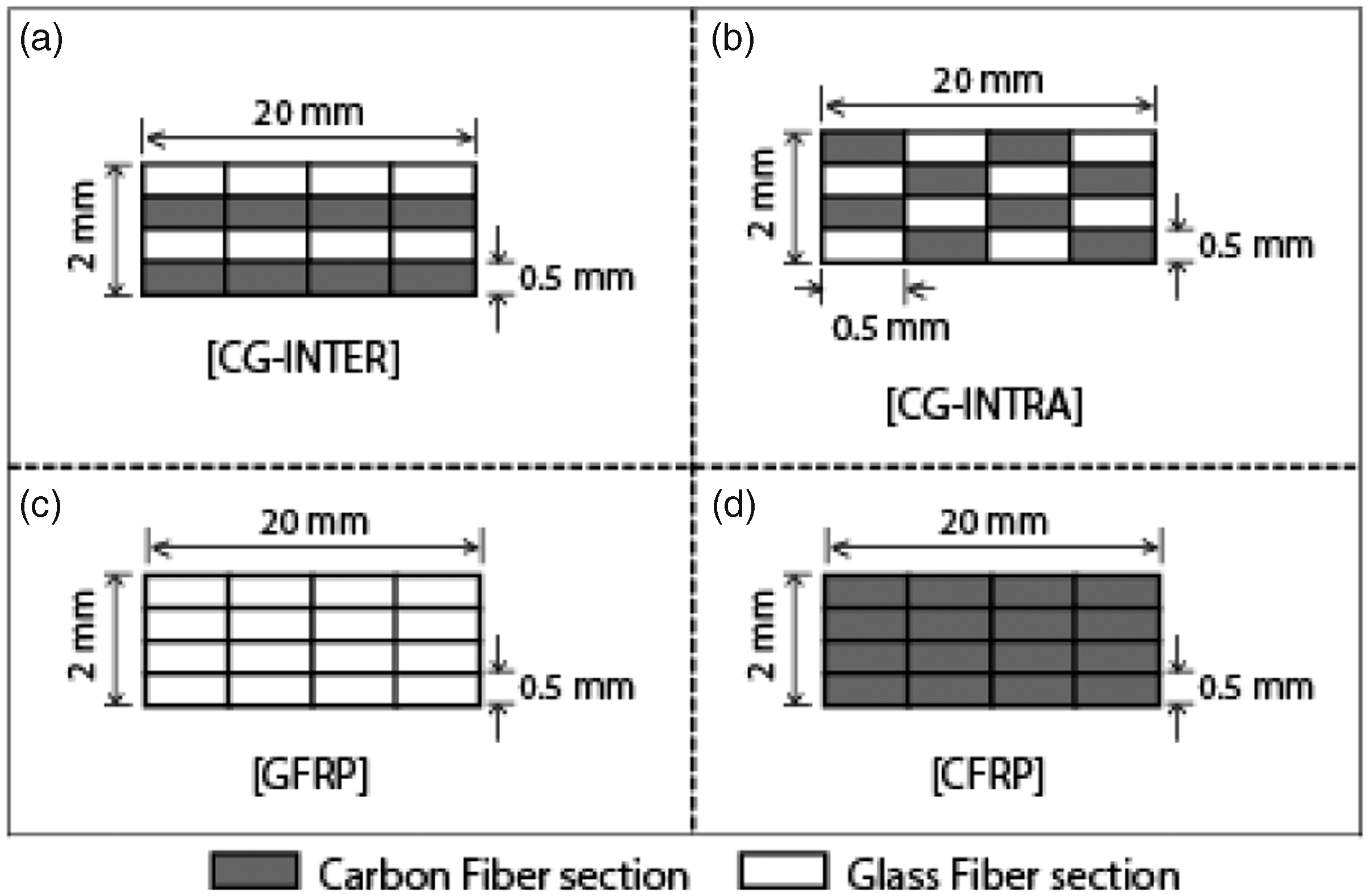
Fiber volume fractions
Overall fiber volume fractions: CFRP 0.56%, [CG-INTER] 0.450%, [CG-INTRA] 0.452%, and GFRP 0.53%. Composite volume fractions: Composite volume fraction is defined as the ratio of volume of one of the constituents of the hybrid composite to the volume of hybrid composite. For hybrids, [CG-INTER] and [CG-INTRA]: T620S carbon composite volume fraction, Vfc = 0.50 and E-glass composite volume fraction, Vfg = 0.50.
Composites manufacturing
Vacuum-assisted resin infusion with the assistance of vacuum bagging method is the manufacturing technique that was applied in the manufacturing of four types of laminated composites. Figure 2(A) schematically shows the vacuum bagging and resin infusion process and Figure 2(B) taken during manufacturing of composites.
(A) Schematic drawing of manufacturing vacuum-assisted resin infusion (VARI) process. (B) Vacuum bagging and resin infusion during composite laminates manufacturing. (a) UD preforms, (b) tool, (c) lay-up, (d) vacuum bagging, (e) oven for curing process.
Plies were arranged according to Figure 1 against the mold side and then the vacuum was applied to pump out the trapped air inside the assembly. Resin properly mixed with hardener was then infused to impregnate the layup. Several items were used in the vacuum bagging process as shown in Figure 2(A). During the curing process, laminates were retained at a constant pressure of 0.1 MPa and at a constant temperature of 60℃ for 6 h.
Tensile test
Tensile properties were determined on a Universal testing machine. Specimen preparation and testing were carried out in accordance with ISO 527:5 technique [34]. Specimen dimension and sample for tensile test is shown in Figure 3(a) and (b). Glass/epoxy tabs were used at each end of the specimen to avoid gripping effects (Figure 3(b)). The sample was held between grippers of the Universal Testing Machine (UTM) and the load was increased until fracture occurred. The loading rate was 2 mm/min (0.034 mm/s) and the experiment was conducted in room temperature. For each sample eight tests were performed. Stress–strain plots were generated. Tensile strengths, tensile modulus, and tensile failure strains were calculated and the results are presented in Table 2. Results were also generated for plain carbon/epoxy composite laminate (CFRP) and plain glass/epoxy composite laminate (GFRP), presented in Table 2. Density of the composites was determined and presented in Table 2. Overall fiber volume fractions were determined as given previously in “Fiber volume fractions” section.
(a) Test specimen dimension and (b) samples for tensile test. Experimental tensile properties of different composites. U: ultimate.

Compression test
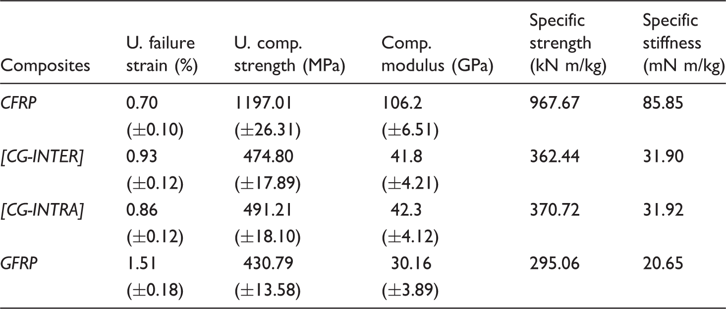
Compressive properties were determined on UTM in accordance with ISO [35] standard test method. Specimen size and sample for compression test is shown in Figure 4(a) and (b). Glass/epoxy tabs were used at each end of the specimen to avoid gripping effects (Figure 4(b)). The specimen was held in a fixture and compressive load was applied to produce compression. The load, 2 mm/min (0.034 mm/s), was applied until the specimen cracked. Eight tests were carried out for each of the samples. Stress–strain plots (from the load–displacement curve) were generated and the average ultimate compressive stress and failure strains were noted (Table 3). Results were also produced for plain carbon/epoxy composite laminate (CFRP) and plain glass/epoxy composite laminate (GFRP), presented in Table 3.
(a) Test specimen dimension and (b) sample for compression test. Experimental compressive properties of different composites.
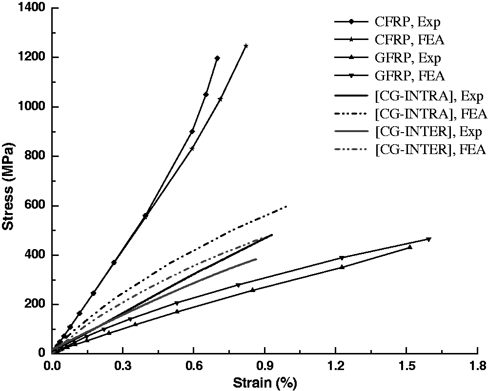
Figures 5 and 6 present the tensile and compressive stress–tensile strain plots for different composite laminates under quasi-static loading from experiments and FEM, respectively. In general, it is seen that the results from the experiments and FEA are in good agreement.
Tensile stress–strain plot. Compressive stress–strain plot.
FEA
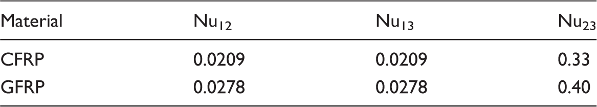
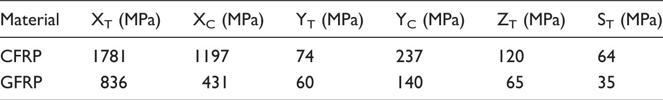
The hybrid composites being investigated in this study are made of two types of fibers, UD T620S carbon and E-glass, into a common matrix, epoxy. The selected mechanical properties of the fibers and the matrix are presented in Table 1. In this study, the tensile and compressive behaviors of hybrid composites are studied using commercial software package ABAQUS/Explicit. Based on the constituent properties, the lamina properties, including the longitudinal modulus E1; the transverse moduli E2 and E3; and the shear moduli G12, G13, and G23 are derived using Hashin’s model [36].
The analysis of the UD composites rectangular material using finite element modeling was carried out on a finite element software package ABAQUS/Standard (Ver. 6.11) on a WINDOWS XP® operation system platform. The part used was of 3D deformable solid and of extrusion type. The materials properties input to the FEM calculation were the density, mechanical properties, and the damage criteria (Tables 4 to 8). The density of the tube composite was calculated from the constituent densities. The rectangular model was loaded in the X-direction as shown in Figure 7(a) and (d). Velocity of the point of load, Figure 7(b) and (e) was set at 0.0334 mm/s to mimic the experimental loading condition of 2 mm/min loading. Encastre boundary condition was applied to one side of the rectangular model as shown in Figure 7(b) and (e). This was to ensure no movement and no rotation in any direction in this end of the model. The meshed hybrid composite rectangular model is shown in Figure 7(c) and (f). Meshing of the model was done with the eight-node reduced integration element (C3D8R). The number of mesh used was 20,000 for tensile test specimen and 1600 for compressive test specimen.
(a) to (f) Loading and boundary conditions, and meshing of hybrid structure [CG-INTER]. Young’s modulus in fiber, transverse, and normal direction of the composite materials. Poisson’s ratio in three directions. Shear modulus in three directions. Tensile and compressive strength in fiber, transverse, and normal direction and transverse shear strength. Density of the composites.


Surface-based cohesive behavior, a simplified way, was used to model cohesive connections with negligibly small interface thicknesses using the traction–separation constitutive model. Figure 8 shows the interfaces at which surface-based cohesive behavior model was used.
Surface-based cohesive FE model for of (a) [CG-INTER] and (b) [CG-INTRA].
Results and discussion
Tensile properties
The tensile stress–strain (determined from the load–displacement curve) curves obtained for analysis of tensile strength (σ = F/A0), strain (ε = ΔL/ L0), modulus (E = F.L0/A0.ΔL), specific strength (σ/ρ), and specific stiffness (E/ρ) of the composite laminates are shown in Figure 5. For each specimen, eight tests have been carried out and the average tensile test data are presented in Table 2. Among all the composite laminates CFRP has the maximum tensile stress, minimum failure strain, and hence the maximum tensile modulus. For pure glass composite, i.e. GFRP it is vice versa. According to brittle property, the curves show low displacement among all the tested structures. In case of CFRP, it is seen that after the crack the structure did not tend to show no plateau region whatsoever and reached directly to a critical point in carrying a high load/stress and led to catastrophic failure. In case of GFRP, the structure showed linearity, ductility (indicating to a high displacement/strain due to the high-elongation property of glass fiber and so the composite structure) but no plateau behavior thereby again failed catastrophically. The hybrid structures to some degree tend to show some ductility because of having a certain amount of brittle carbon fiber and ductile glass fiber within their structures. However, in terms of final failure it is noticed that they also failed catastrophically. Figure 3(b) shows the specimens after tensile test under quasi-static tensile loading and Figure 9(a) to (d) shows the stress contour of the specimens after FE tensile tests.
(a, c) Contour of stress in the fiber direction, (b, d) delamination developed in the specimens (tensile loading).
According to tensile strength and tensile modulus these composite configurations can be presented as: [CFRP] > [CG-INTRA] > [CG-INTER] > [GFRP] and for tensile failure strain it is [CFRP] < [CG-INTER] < [CG-INTRA] < [GFRP]. Tensile strength and modulus values of hybrid composites lie in between those of plain carbon and plain glass fiber reinforced composites. This is due to hybridization where each materials share their properties in between (CF loses strength and GF gains strength) depending on their proportion into the mixing ratio, which means that a greater proportion of carbon fiber would certainly offer greater tensile strength and tensile modulus and so specific strength and specific stiffness (Table 2). In case of ultimate tensile failure strain, it is vice versa (CF gains strain and GF loses strain). In this experiment, a comparative study has been made of hybridization technique to see whether the interlayer hybridization or the intralayer hybridization exhibits better performance and a focus has been given on the mechanisms behind it.
From the summary of the test data it is seen that tensile properties of hybrid composite [CG-INTRA] are to some extent better than those of hybrid composite [CG-INTER]. Although the difference is not very significant yet a bit better performance is attributed by the intralayer hybrid structure. In other words, for hybrid composites, placing carbon and glass fibers in each layer alternatingly (intralayer) gives out comparatively better tensile properties (e.g. strength, see Table 2) than when they are placed layer by layer (interlayer). In case of tensile modulus, a similar conclusion can be drawn and the finding concurs with Ren et al. [22] who in his paper reported a higher modulus for intralayer than interlayer UD carbon/carbon hybrids. For the hybrid composite configuration [CG-INTRA], the carbon fiber parts are distributed within the layers and they are surrounded by glass fiber parts in a better way than hybrid configuration [CG-INTER] (Figure 1). Ren et al. [22] pointed out factors those might influence the small reported deviations are crimp, fiber misorientations, and/or measurement inaccuracies in the fiber volume fraction. In case of specific strength and specific stiffness it is seen that [CG-INTRA] somewhat possesses a bit better results though the deviations between specific stiffness are negligible (Table 2).
Since the tensile failure strains of glass fiber are more than carbon fibers, possible damage evolution in carbon fiber parts is constrained because of surrounding glass fiber parts. As a result of this, carbon fiber parts could take more strain before failure of the layer and hence the tensile failure strain of hybrid configuration [CG-INTRA] is higher. For the hybrid composite configuration [CG-INTER], the carbon and glass fiber layers are arranged layer by layer, only the third layer is sandwiched within the second and fourth layer of glass fibers (Figure 1). The first layer is at the exterior and is not constrained by the high strain glass fiber layer. Hence, the hybrid composite configuration [CG-INTER] has a relatively low tensile failure strain than hybrid configuration [CG-INTRA]. Nevertheless, the tensile failure strain of [CG-INTER] is more than plain carbon/epoxy composite laminate.
It is seen that the CFRP and GFRP fail catastrophically whenever the maximum tensile strength is reached. On the other hand, for hybrid composites [CG-INTRA] and [CG-INTER], carbon fibers fail first followed by glass fiber parts. The properties of the hybrid composites are compared with those of plain carbon composite. The tensile strength of CFRP is 1781.31 MPa, whereas it is 1033.86 and 1088.46 MPa for hybrid configurations [CG-INTER] and [CG-INTRA], respectively (Table 2). In other words, there is a loss tensile strength of 41.96% for [CG-INTER] and 38.89% for [CG-INTRA]. A drop in specific strength and specific stiffness is also noticed (Table 2). Tensile failure strain of CFRP is 1.60%, for [CG-INTER] it is 2.01%, and for [CG-INTRA] it is 2.08%. In other words, there is a gain of failure strain of 25.62 and 30.0% tensile failure strains for hybrid configurations [CG-INTER] and [CG-INTRA], respectively. It is noted that percentage loss in tensile strength is higher than percentage gain in tensile failure strain. In a work on two types of hybrid composites reinforced with carbon T300 (8 H satin weave fabric) and E-glass fabric in epoxy, the authors [21] reported that hybrid composites lose tensile strength and gain tensile strain while compared to plain carbon composite. In particular, a loss of 17.2% of tensile strength and a gain of 90.4% of tensile strain have been reported for hybrid composite H1 [G3C2]s when compared to plain carbon composite [21]. The difference between the results obtained from this work and with those have been mentioned in previous work could arise due to having materials and preforms being used.
This illustrates that to improve the failure strain problem of plain carbon composite, mixing glass fiber with it hence turning it to a hybrid configuration could be an effective way. However, there should be a negotiation between other properties, e.g. tensile strength.
Compressive properties
The compressive stress–strain (determined from the load–displacement curve) curves obtained for analysis of compressive strength (σ = F/A0), strain (ε = ΔL/ L0), modulus (E = F.L0/A0.ΔL), specific strength (σ/ρ), and specific stiffness (E/ρ) of the composite laminates are shown in Figure 6. For each specimen, eight tests have been carried out and the average compressive test data are presented in Table 3.
Among all the composite laminates CFRP has the maximum compressive stress, minimum failure strain, and hence the maximum compressive modulus. For pure glass composite i.e., GFRP it is vice versa. According to brittle property, the curves show low displacement among all the tested structures. In case of CFRP, it is seen that after the crack the structure did not tend to show no plateau region whatsoever and reached directly to a critical point in carrying a high load/stress and led to catastrophic failure. In case of GFRP, the structure showed linearity, ductility (indicating to a high displacement/strain due to the high-elongation property of glass fiber and so the composite structure) but no plateau behavior thereby again failed catastrophically. The hybrid structures to some degree tend to show some ductility because of having a mixture of certain amount of brittle carbon fiber and ductile glass fiber within their structures. However, in terms of final failure it is noticed that they also failed catastrophically. Figure 4(b) shows the specimen [CG-INTRA] after quasi-static compression test and Figure 10(a) to (d) shows the stress contour of the specimens after FE compression test.
(a, c) Contour of stress in the fiber direction, (b, d) delamination developed in the specimens (compressive loading).
According to compressive strength and compressive modulus these composite configurations can be presented as: [CFRP] > [CG-INTRA] > [CG-INTER] > [GFRP] and for compressive failure strain it is [CFRP] < [CG-INTRA] < [CG-INTER] < [GFRP]. Compressive strength, modulus, specific strength, and specific stiffness values of hybrid composites lie in between those of plain carbon and plain glass fiber reinforced composites (Table 3). This is due to hybridization where each materials share properties among themselves (CF loses strength and GF gains strength) depending on their relative proportion into the mixing ratio, which means that a greater proportion of carbon fiber would certainly offer greater compressive strength and compressive modulus and so specific strength and specific stiffness (Table 3). In case of ultimate compressive failure strain, it is vice versa (CF gains strain and GF loses strain). The possible mechanism and science behind such behavior could be explained as it has been done in earlier “Tensile properties” section.
Compressive properties of hybrids are compared to those of plain carbon composite. Reductions in compressive strength for hybrid composites were noted accounting 60.33% for hybrid [CG-INTER] and 58.96% for hybrid configuration [CG-INTRA]. The compressive failure strain of hybrids is marginally more than the compressive failure strain of CFRP accounting 32.85 and 22.85% higher for hybrid configurations [CG-INTER] and [CG-INTRA], respectively. Reduction in compressive strength was found not to be very significant in a work on two types of hybrid composites reinforced with carbon T300 (8 H satin weave fabric) and E-glass fabric in epoxy [21]. Though in terms gain of compressive strain seems to be very high and as reported both hybrids (H1 [G3C2]s and H2[C2G3]s) exhibit nearly same ultimate compressive strains [21]. Due to different types of materials and preforms being used in this work and in previous work, the differences between the results are certain. Nonetheless, loss in compressive strength and gain in compressive strain have been found in both works.
Here again, it is seen that to improve the failure strain of carbon fiber hybridization could be an effective way and a trade-off between strength and strain has to be made.
Hybridization effect
Tensile strength and modulus
Basing on the mechanics of materials approach to strength [37] under quasi-static tensile loading, tensile strengths of hybrid composite laminates are presented in Figure 11(a). Rule-of-mixtures (RoMs) approach, equation (2), for calculating the strength of hybrid composites is presented in Appendix 1.
(a) Tensile and (b) compressive strengths obtained from experiment and using RoM.
Experimentally obtained tensile strength values for hybrid composites [CG-INTER] and [CG-INTRA] are presented against rule of mixtures in Figure 11(a). The experimentally obtained tensile strength values of hybrid composites are lower than those obtained using RoMs, meaning the experimental results do not agree with RoMs. This is because of hybridization effect and negative hybrid effect exists, calculated using equation (3), given in Appendix 1. Precisely, the tensile strength obtained using RoMs is 1399.6 MPa, whereas those for hybrid composites [CG-INTER] and [CG-INTRA] are 1033.5 and 1088.46 MPa, respectively. In other words, there a negative hybrid effect of -26.15% on tensile strength for hybrid composite [CG-INTER] exists and -22.23% for hybrid composite [CG-INTRA] compared to tensile strength obtained using RoMs. The existence of hybridization effect on tensile strengths was reposted by many researchers [7,8,21,38–43]. Negative hybrid effects for tensile modulus are noticed with -27.09% for [CG-INTER] and -25.30% for [CG-INTRA].
According to many authors, the hybrid effect for tensile strength [8,15–17] is based on a bilinear RoMs and the longitudinal tensile modulus [8,20,44] of hybrid composites obey a linear RoMs. In most cases, the values deviating from these behaviors are due to variation in volume fraction or fiber orientations. However, Phillips [45] reported that some deviations are due to an incorrect use of RoMs. The relative volume fractions of both constituent fibers should be taken into account while calculating the property using RoMs approach. But these are often difficult to measure separately in hybrid composites and in most cases they are estimated based on ply fraction or tow fraction. These estimations do not necessarily depend linearly on the fiber volume fraction which means that the RoMs would not be linear either. Hybrid effect might not exist in the longitudinal direction but can still occur in the transverse direction, where the RoMs is not linear and often less accurate. Taketa [46] reported positive hybrid effect for transverse tensile modulus of UD carbon fiber reinforced polypropylene (PP) hybridized with woven self-reinforced PP. This is due to high Poisson’s ratio of the self-reinforced PP, meaning that it has a high tendency to shrink in the transverse direction [46].
Compressive strength and modulus
Basing on mechanics of materials approach to strength [37] under quasi-static compressive loading, compressive strengths of hybrid composite laminates are presented in Figure 11(b). The experimentally obtained compressive strength values of hybrid composites are lower than those obtained using RoMs approach; therefore, negative hybrid effect exists. Precisely, the compressive strength obtained using RoMs is 599.4 MPa, whereas those for hybrid composites [CG-INTER] and [CG-INTRA] are 474.8 and 491.21 MPa, respectively. In other words, there a negative hybrid effect of -20.78% on compressive strength for hybrid composite [CG-INTER] exists and -18.04% for hybrid composite [CG-INTRA] compared to compressive strength obtained using RoMs. Negative hybrid effects occur for compressive modulus with -38.69% for [CG-INTER] and -37.95% for [CG-INTRA]. Hybridization effect on compressive properties has been reported in many literatures [5,8,23,24].
Tensile failure strain
In the same way, the existence of positive hybrid effect on tensile failure strain is found in this work (Figure 12(a)). Precisely, the tensile failure strain obtained using RoMs is 1.92%, whereas those for hybrid composites [CG-INTER] and [CG-INTRA] are 2.01 and 2.08%, respectively. In other words, there a positive hybrid effect of +4.68% on tensile failure strain for hybrid composite [CG-INTER] exists and +8.33% for hybrid composite [CG-INTRA] compared to tensile failure strain obtained using RoMs. The existence of hybrid effect for failure strain has been reported in many literatures [14,15,21,44,47–50].
(a) Tensile and (b) compressive failure strains obtained from experiment and using RoM.
A typical range of hybrid effect for failure strain is 10–50% although some extreme deviations from the mean have been reported. Kretsis [8] calculated negative hybrid effect down to –66% using Chamis et al. [51] data and the results were discarded as unrealistic values. Aveston and Sillwood [52] reported a hybrid effect of +116% in carbon/glass interlayer hybrids, but this is mainly due to an unreasonably low failure strain for the carbon fiber reinforced composite. Based on these early reports it can be said that the hybrid effect in hybrid composites found in this work using current generation carbon fibers (e.g. T600) is smaller. Pandya et al. [21] on a work on carbon/glass hybrid composite reported a hybrid effect of +36 and +90%. The degree of dispersion was low because of having the relative carbon fiber content to 0.47 and the results seem unusually higher than the trends predicted by Kretsis [8]. Zhang et al. [50] hybridized woven glass and carbon fiber and found improvements in failure strain, ranging between 10 and 31%.
If both fibers are linearly elastic, then the tensile modulus follows a linear RoMs in the fiber direction. However, if it is experimentally observed that the failure strain is enhanced, then the tensile strength should also be enhanced. This is not as straightforward as it seems though. The reason for the failure strain enhancement is often a more gradual failure which means that the last part of the tensile stress–strain diagram is not linear anymore. In some cases, the tensile diagram has a plateau near the end [48,53] and the composite behaves like a pseudo-ductile material.
Compressive failure strain
In case of compressive failure strain, the existence of negative hybrid effect is noticed (Figure 12(b)). Precisely, the failure strains of [CG-INTER] and [CG-INTRA] are 0.93 and 0.86%, respectively. Failure strain calculated using RoM approach is 1.105%. It is seen that the experimental values are smaller than that of obtained using RoM, therefore, negative hybrid effect occurs. Negative hybrid effect of –15.83% occurs for [CG-INTER] and –22.17% for [CG-INTRA]. Nevertheless, the compressive failure strains of both hybrid composite laminates are higher than that of reference plain CFRP. To measure the hybrid effect accurately, tensile and compressive tests have got to be carried out very precisely both on the hybrid composites and the reference carbon fiber reinforce composites. Since this work comprises UD hybrids therefore, measuring hybrid effect is more difficult than multidirectional composites. It has been reported that stress concentrations at the grips may be less detrimental in hybrid composites than in nonhybrid composites [53] and this could lead to an overestimation of the hybrid effect.
Considering the discussion made above it can be concluded that hybridization is a trade-off between increase in failure strains thereby making the composites more damage tolerant, e.g. resistant to impact and decrease in in-plane strengths, e.g. tensile and compressive of hybrid composites compared with high-modulus, low-elongation fiber composites.
Damage analysis
The morphological analysis of the tested samples was performed using scanning electron microscope (SEM). The samples from tensile and compression tests were studied using SEM (Hitachi TM3000 microscope). Each sample was dried and sputtered with a layer of gold of thickness of 15–20 nm using an ion-sputter device.
Figure 13(a) and (b) presents the SEM images after tensile and compression test, respectively. The UD arrangement of the fibers is clearly seen in both images. This type of fiber arrangement yields better mechanical properties in the longitudinal direction. In both SEM images, the bonding between the fiber and the resin is seen, which indicates the composite is more likely to fail due to breakage of fibers than by debonding of fibers. In comparison, the fiber damage of the carbon fiber part was more severe than glass fiber section (Figure 13(b)), due to having a significantly low failure strain. Matrix cracking in glass fiber part was more prominent (Figure 13(a)).
(a) and (b) SEM micrographs of the specimens after tensile and compression tests.
Nonvisible damage to composite structures is a significant concern in many composite industries. To understand the nonvisible damage, i.e. delamination occurred at the composites a cohesive zone modeling was used in FE modeling (Figure 8). Cohesive behavior is useful in modeling adhesives and bonded interfaces. Figure 9(b) and (d) shows the delamination occurred at the specimens after being subjected to tensile loading in FE analysis. Since having significant differences in properties and the glass and carbon fiber parts without interlacing leaded to delamination. The specimen developed delamination in the interfaces between carbon and carbon is to some extent less than the delamination in the interface between carbon and glass. Figure 10(b) and (d) shows the delamination developed in the specimen after subjected to compressive loading.
From the SEM image, Figure 13(a) it is noticed that under tensile loading the low-elongation carbon fiber breaks first followed by high-elongation glass fiber. A similar explanation made by Kretsis [8] who reported that the weakest low-elongation fibers that break first form cracks that are “bridged” by the surrounding high-elongation composite, thus allowing the stronger low-elongation fibers to reach their ultimate strength. Manders and Bader [15] pointed out that, “the hybrid effect arises from a failure to realize the full potential strength of the fibres in all-carbon fibre composites, rather than from an enhancement of their strength in the hybrids.”
Conclusion
FEM models are attempted to simulate the tensile and compressive properties of interlayer and intralayer carbon glass/epoxy hybrid composite laminates. The tensile and mechanical properties are evaluated to validate the FEA models. The experimental results and the FEA results are in good agreement. The properties of hybrid composites [CG-INTER] and [CG-INTRA] are compared with those of UD T620S carbon/epoxy composite laminate and UD E-glass/epoxy composite laminate. For hybrid composites, placing carbon and glass fiber parts alternatingly in every layer (intra-layer) gives out higher tensile strength and tensile failure strain than placing carbon and glass fibers layer by layer (interlayer). An increase of 5.28% in tensile strength is noticed for intralayer hybrid (1088.46 (±38.60) MPa) as compared to interlayer hybrid (1033.86 (±38.60) MPa) configuration. An increase of 3.48% in tensile failure strain is noticed for intralayer (2.08((±0.05)%) hybrid as compared to interlayer hybrid (2.01((±0.05)%) configuration. An increase of 3.45% in compressive strength is noticed for intralayer (491.21(±11.60) MPa) hybrid composite as compared to interlayer hybrid (474.8(±11.60) MPa) configuration. On the other hand, an increase of 8.13% in compressive failure strain is noticed for interlayer hybrid (0.93(±0.05)%) as compared to intralayer hybrid (0.86(±0.05)%) configuration. Although the difference between the properties of intralayer and interlayer is not very significant yet a bit better performance is attributed by the intralayer hybrid structure. Percentage loss in tensile strength and percentage gain in tensile failure strain are noticed for both hybrid types when compared to those properties of CFRP and the percentage loss in tensile strength for hybrid composite is higher than percentage gain in tensile failure strain. Negative hybrid effect of up to -26.15% for tensile strength occurs for hybrid composite [CG-INTER] and -22.23% for hybrid composite [CG-INTRA]. There is a loss of compressive strength of 60.33% and 58.96% for hybrid composites [CG-INTER] and [CG-INTRA], respectively, when compared to that of CFRP. Negative hybrid effect of up to -20.78% on compressive strength occurs for hybrid composite [CG-INTER] and -18.04% for hybrid composite [CG-INTRA]. Positive hybrid effect of up to +4.68% on tensile failure strain occurs for hybrid composite [CG-INTER] and +8.33% for hybrid composite [CG-INTRA]. Compressive strength of [CG-INTER] is of the order of 46% of tensile strength while modulus is of the order of 73.2% tensile modulus. Hybrid composite [CG-INTRA] also bears same kind of results. According to this research, hybrid composites enhance the failure strain which makes the composites more damage tolerant, i.e. to have better impact properties while minimizing the cost of an advanced composite material. Also intralayer hybrid yields better mechanical properties while compared to interlayer hybrid configuration.
Footnotes
Declaration of Conflicting Interests
The author(s) declared no potential conflicts of interest with respect to the research, authorship, and/or publication of this article.
Funding
The author(s) disclosed receipt of the following financial support for the research, authorship, and/or publication of this article: This work was supported by the “Science and Technology Commission of Shanghai Municipality (Funding No: 15XD1524700)” and “Shanghai Municipal Commission of Economy and Informatization (Funding No: CXY-2013-11)”.