
Abstract
Warp-knitted spacer fabrics for cushion products are in contact with different parts of human body. Surface shapes of most contacting parts can be simplified as spherical caps, while there are few reports on relationship between sphere diameter and compression property of spacer fabric. Therefore, the main content dealt with in the paper was to conduct spherical compression and simulation analysis of warp-knitted spacer fabrics. Five spherical indenters were selected and three compression indices were featured. Comparisons of compression indices results of spacer fabrics amongst five spherical indenters exhibited good relations. Moreover, spherical compression behavior was simulated by finite element method to better understand the mechanism of spherical compression deformation of warp-knitted spacer fabrics. The results that relative errors of the compression indices were all small showed a good accordance between theoretical and experimental results; then, stress distribution and displacement evolutions were analyzed to discover deformation mechanism of spacer filaments compressed. It is effective to simulate the spherical compression performance between different parts of human body and spacer fabric.
Introduction
Warp-knitted spacer fabrics (WKSF) are produced into ergonomic cushion materials and apparel products by designing special structure for a wide range of applications, such as functional bra support [1], buffer clothing [2], knee braces [3], insole and bed mattress [4,5] and car seats [6]. Moreover, WKSF could be used as the reinforcement of many industrial materials. Researchers successfully made a completely new type of 3D fabric to make advanced cement based matrix reinforcement, which significantly provided excellent structure textiles for textile-reinforced concrete application [7,8]. Theoretical models and characterization of physical properties of spacer fabric were investigated, such as stab-resistant property [9], compression behavior [10,11], impact behavior [12–14], theoretical modeling [15–17], sound absorption [18,19], pressure reduction [20] and comfort properties [21,22]. For ergonomic products, there exist action and reaction between WKSF and human body. Surface shapes of some parts of the human body contacting with WKSF could be simplified as spherical caps [23], while surface shapes of other parts could be simplified as flat shapes. For preparing ergonomic and comfortable WKSF, the key is to study theoretical and experimental compression behavior of WKSF by spherical compression and plane plate compression. The compression indices of plane plate compression of WKSF were featured to characterize compression property, which was also a good way to study the effect of thermal and moisture conductivity property [24,25] of WKSF compressed. For exploring the interaction between WKSF and spherical indenter, researchers established theoretical modeling to discuss the influence of structural parameters of WKSF on compression behavior and set up a good correlation between plane plate compression and spherical compression of WKSF [26]. Wherein, spherical indenter was generally used to simulate different parts of the human body. It is effective to feature characteristic index to analyze compression interaction between human body and WKSF.
Surface shapes of different contacting parts of human body can be simplified as spherical caps with different radius of curvature. In order to reveal spherical compression of spacer fabric resulting from different contacting part of human body, the paper aimed to conduct spherical compression and simulation analysis of WKSF compressed by spherical indenter with variable diameters. It also discussed the accordance of spherical compression property of WKSF compressed by five spherical indenters, which was useful for establishing a standard method to test spherical compression of WKSF by an indenter with specified diameter. Then, spherical compression behavior is simulated by finite element method (FEM) to discover the stress and displacement evolutions of spacer filaments so as to better understand the mechanism of spherical compression deformation of WKSF. It is helpful to simulate spherical compression performance between different parts of the body and WKSF in application.
Experimental
Samples preparation
Specifications of 10 warp-knitted spacer fabrics.

Compression instrument
Compression tester JA12002 was selected to conduct spherical compression test (Figure 1). Spherical indenter connected with a force sensor was driven by a motor fixed on a main frame to compress spacer fabric pasted on surface of the plane plate. The compression speed was 12 mm/min. The plane plate was a circular with diameter 24 cm. Five spherical indenters were chosen with diameters 5 cm, 8 cm, 12 cm, 16 cm and 18 cm, respectively. Double-side adhesive tapes were used to stick spacer fabric on the surface of the plane plate to avoid slippage phenomenon. In order to have a good comparison, all spherical compression tests of spacer fabrics were set as the same maximal compression strain 0.70.
Schematic diagram of plane plate compression testing method.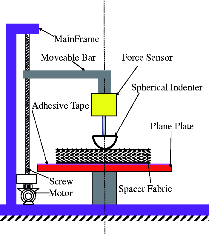
Results and discussion
Typical compression force and strain curves
Typical compression force and strain curves of spacer fabrics compressed by a spherical indenter with diameter 5 cm are shown in Figure 2, wherein compression strain is the ratio of compression distance of spherical indenter to thickness of spacer fabric.
Typical compression force and strain curves of spacer fabrics.
Compression indexes of spacer fabrics under five spherical indenters.
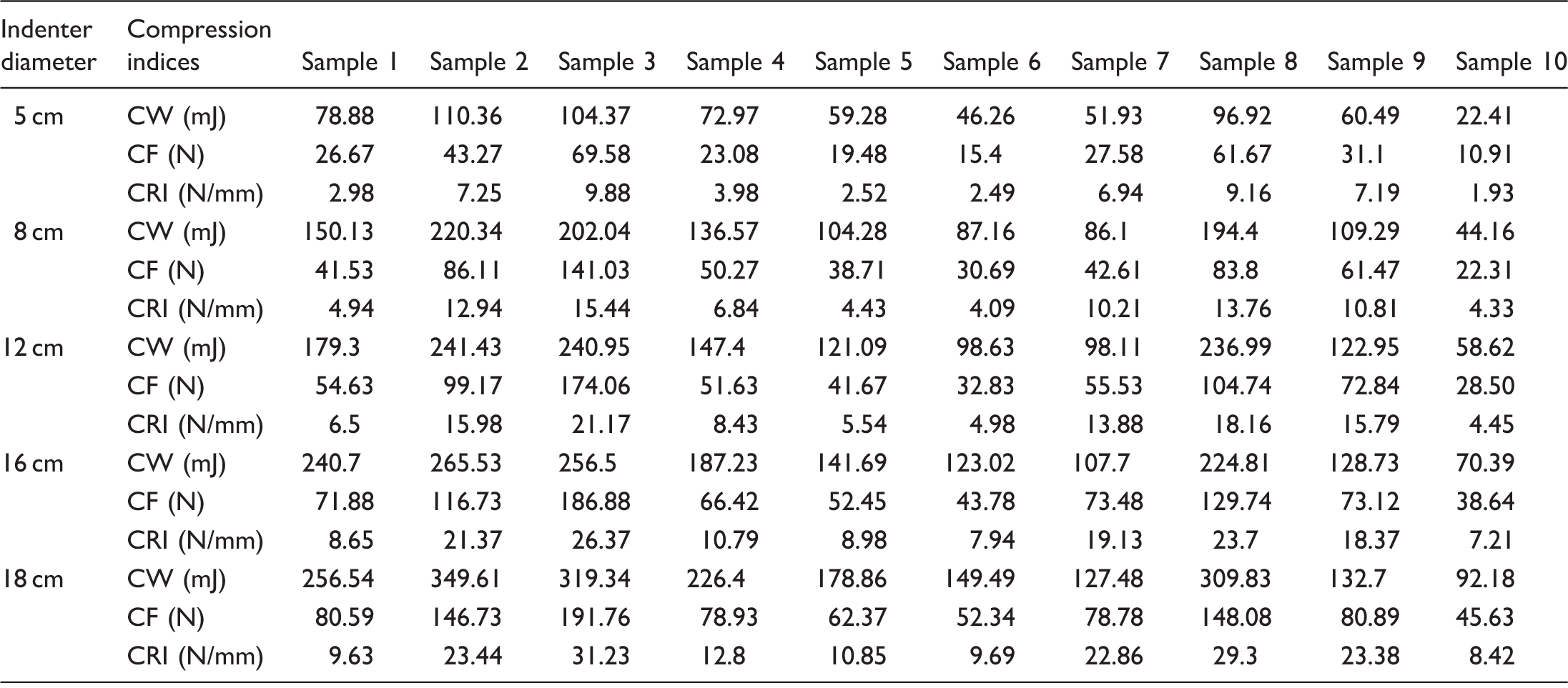
CW: compression work; CF: maximum compression force; CRI: compression resistance index.
It can be concluded from Table 2 that CW, CF and CRI all increase with the increase of indenter diameter. It may be explained that the contacting area between spacer fabric and spherical indenter significantly ascends with the increase of diameter of spherical indenter. So, CW and CRI also increase with the rising of compression force. Moreover, 10 spacer fabrics are selected with comparable structures. Effects of structure of spacer fabrics are analyzed as follows. Spacer fabrics (1, 2 and 3) were knitted with varying thickness being 13.81 mm, 9.28 mm and 7.45 mm, respectively. Their CF, CRI and CW all showed ascending trend when spacer thickness reduced from 13.81 mm to 7.45 mm. Spacer fabrics (4, 5 and 6) were designed with different spacer filament angles being 55.60°, 39.86° and 28.54°, respectively. Spacer filament angle is the angle of filament direction to the surface of spacer fabric. When spacer filament angle decreased from 55.60° to 28.54°, CW, CF and CRI showed similar descending trend. It is due to the fact that spacer filament gradually changes to be vertical with the increase of spacer filament angle, and more compression force and work are required to compress the spacer filaments.
Spacer fabrics (3, 8 and 10) were knitted by different spacer filament diameters being 185.54 µm, 170.61 µm and 137.64 µm, respectively. Effect of spacer filament diameter on the compression indices was obvious from Table 2. It demonstrates that the greater the diameter, the larger the CW, CF and CRI. It may be attributed to the obvious reason that the larger force is required to compress a single spacer filament with greater diameter. So, CW and CRI present the similar ascending trend as CF when diameter of spacer filament increases.
The arrangement shape of side view of spacer filaments shows V shape for spacer fabric 7 and X shape for spacer fabric 9, which affects the compression property of spacer fabric. On the whole, CW, CF and CRI of spacer fabric 9 were all larger than those of spacer fabric 7. X-shape arrangement of spacer filaments between the two surfaces forms a double zigzag, so CF of spacer fabrics enhances when compressing spacer filaments. CW and CRI exhibit the similar increasing trend as CF. It should be noted that when the arrangement of spacer filaments is X shape, the structure of spacer fabric is relatively stable.
Relationships of spherical compression indices between indenters
Correlation of compression indices among five spherical indenters.
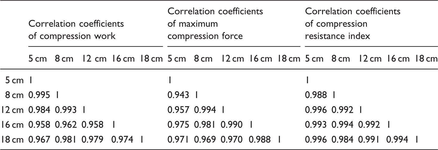
It is obvious from Table 3 that characteristic indices of spherical compression manifest significant correlations among five spherical indenters with diameters 5 cm, 8 cm, 12 cm, 16 cm and 18 cm, respectively. The minimum correlation coefficients of CW, CF and CRI were 0.958, 0.943 and 0.984, respectively. Moreover, results of the three compression indices in Table 2 showed similar positive correlation with the increase of compression strain. CW, CF and CRI all ascended when the diameter of spherical indenter became larger. It is due to the fact that both the contacting area between spacer fabric and spherical indenter and the number of spacer filaments supporting the compression force are improved under the same compression strain. Then, compression force reacting on the spherical indenter correspondingly enhances.
So, it could be concluded from Tables 2 and 3 that compression behavior of spacer fabrics compressed by five spherical indenters possess significant and direct correlations. It manifests that the spherical compression property of spacer fabric can be effectively characterized by spherical indenters with diameter from 5 cm to 18 cm.
Comparison of compression property between theoretical and test results
In order to understand spherical compression deformation, FEM is adopted to simulate spherical compression deformation of spacer fabrics in Figure 3.
Assembly diagram of spherical compression by finite element method.
For finite element modeling, the following assumptions are made according to geometry of spacer fabric. First, when spacer fabric is compressed, the compression force is mainly supported by spacer filaments because of the upper and bottom layers of spacer fabrics being hexagonal mesh structure. So, the surface structure has a minimal effect on compression performance and the surface structure can be regarded as a homogeneous isotropic thin plate. Second, spacer filaments are all polyester filaments with circular cross-sectional shape and friction coefficient is set as 0.243 under interaction. Third, the compression deformation is limited within elastic deformation. Plastic deformation is negligible, and spacer filaments are simplified as elastic rod and do not change original length under compression. Finally, it is assumed that there is no lateral displacement between spacer filaments and surface layers. It is the reason that the loop structure of surface layer is very tight, and there is a strong attachment constraint at both ends of spacer filaments.
Finite element model was established and the compressive strain was limited within 0.6. In order to explore the regulation of compression performance under five spherical indenters, compression performance of sample 9 was analyzed. In the FEM, Young’s modulus, Poisson’s ratio and volume density of upper and lower plates were 86.7 MPa, 0.3 and 1.38 × 10³ kg/m3 respectively, and Young’s modulus, Poisson’s ratio and volume density of spacer filaments were 6773.3 MPa, 0.3 and 1.38 × 10³ kg/m3, respectively, and Young’s modulus, Poisson’s ratio and volume density of indenters were 210 GPa, 0.3 and 7.9 × 10³ kg/m3, respectively. Then, theoretical and experimental compression force and strain curves acquired by FEM and experiments are shown in Figure 4, and corresponding relative errors are listed in Table 4.
Compression force and strain curves of theoretical and experimental results of sample 9. Relative errors of theoretical and experimental results of compression indices.

It could be seen from Figure 4 that compression force increases with the increase of indenter diameter, which indicates the similar changing trends between the simulated and experimental values of spherical compression under different indenters. The relative errors of CW in Table 4 changed from 0.12 to 0.19 when spherical indenters diameters varying from 5 cm to 18 cm, relative errors of CRI varying from 0.07 to 0.21 and relative errors of CF changing from 0.04 to 0.23, respectively. The trends of simulated and experimental results are very close when relative errors of the three compression characteristic indices ranged within 4–23%. There exists good accordance according to the relative errors of CW, CRI and CF between theoretical and measured results in Table 4. Therefore, it is effective to simulate the spherical compression performance of spacer fabrics by designing different structural parameters and is efficient to build structure models of spacer fabric based on FEM to theoretically analyze compression property of spacer fabric in application.
Analysis of displacement of upper layer of spacer fabrics
In order to analyze displacement change of upper layer of spacer fabric compressed by spherical indenter, the edge path of the upper layer is selected (as shown in Figure 5) and the corresponding displacement curves along the vertical direction are acquired when compression distance is 4 mm (as shown in Figure 6).
Displacement change of upper layer of spacer fabric under spherical compression. Displacement curves of upper layer under five indenters.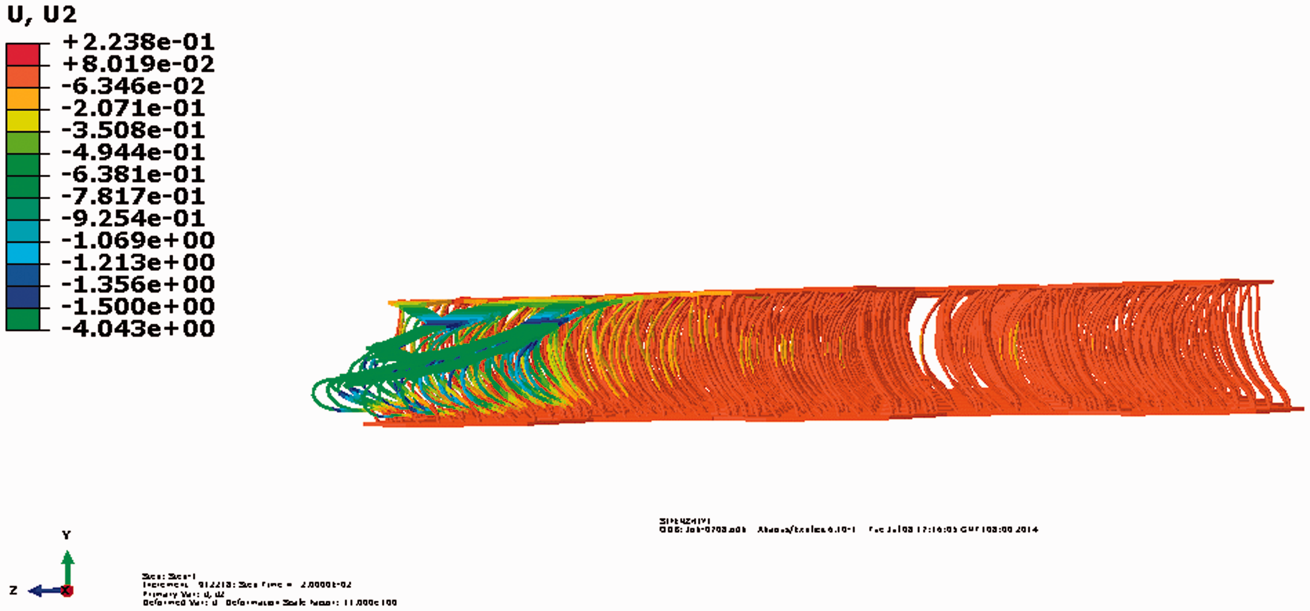

When spherical indenter compresses the spacer fabric, there exists a contacting part and a non-contacting part between spherical indenter and spacer fabric. It demonstrates that the spacer filaments support some compression force and reflects the force diffusion performance of spacer fabrics under compression. The larger the diffusion range of displacement, the better the pressure reduction property. So, it is effective to analyze the effect of displacement curve shape and diffusion form on spherical compression of spacer fabrics.
Displacement curves in Figure 6 demonstrates that displacement of element of the upper surface decreases with the increase of distance from the center position, and different indenter significantly affects displacement value of compression gradient. The greater the diameter of spherical indenter, the farther the distance of element with vertical displacement from center point. It also verifies much more spacer filaments undergoing compression deformation, which is useful for spacer fabric compressed to distribute compression force into a larger area for reducing stress concentration.
In addition, in order to obtain the deflection of the different parts and different moment intervals of fabric, seven points in the horizontal direction are selected and their displacement curves under compression are shown in each moment interval, as shown in Figure 7.
Displacement curves at different time. (a) t = 0 s, (b) t = 0.004 s, (c) t = 0.008 s, (d) t = 0.012 s, (e) t = 0.016 s and (f) t = 0.02 s.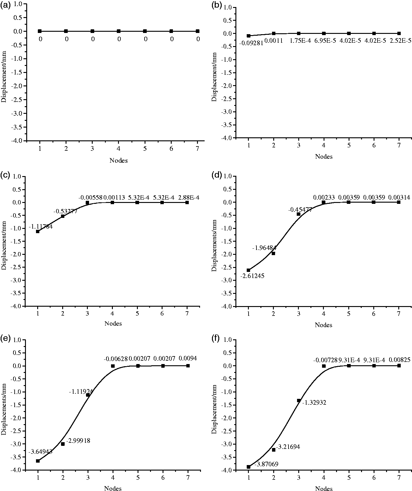
Displacement of the node in Figure 7 changes when spacer fabrics are compressed from time 0 s to 0.02 s. Displacement was zero at time 0 s. Afterwards, the first two nodes closer to center of spherical indenter moved down about 0.092 mm and 0.001 mm, respectively, while the displacements of other nodes were very small at time 0.004 s. The third node started to move down about 0.006 mm at time 0.008 s, and the fourth and the fifth nodes commenced to move down at time 0.012 s and 0.016 s, respectively. When time was 0.02 s, the maximum displacements of the first node, the second node and the third node were 3.871 mm, 3.217 mm and 1.329 mm, respectively, while the sixth and seventh nodes just began to move down. Figure 7 demonstrated that displacement of nodes increased with the increase of compression strain of spacer fabric, i.e., compression time from 0 s to 0.02 s. In addition, the number of nodes supporting the compression force also enhanced. It stresses that the displacement diffuses outwardly along transverse direction, while the displacement decreases rapidly with the increase of the horizontal distance from center of spherical indenter. Displacement curves reflect the deformation shapes of spacer fabrics at different time, which is helpful to analyze the deformation of spacer filaments at different time.
Analysis of stress distribution
Stress changes of spacer fabrics in compression process by spherical indenter diameter 5 cm featured by finite element simulation are shown in Figure 8, where stress nephograms are corresponding to compression times 0 s, 0.004 s, 0.008 s, 0.012 s, 0.016 s and 0.02 s, respectively.
Stress nephograms of spacer fabrics at different time. (a) t = 0 s, (b) t = 0.004 s, (c) t = 0.008 s, (d) t = 0.012 s, (e) t = 0.016 s and (f) t = 0.02 s.
Stress nephograms indicated that stress diffused outwardly when spacer fabric compressed from time 0 s to 0.02 s, and the area enlarged with the deformation of spacer filaments becoming larger. The external compression force firstly contacted and acted on the upper layer, then extended into the bottom layer of spacer fabrics through spacer filaments. Figure 8 obviously showed that the compression forces were mainly supported by spacer filaments; moreover, the area supporting compression force was larger than the contacting area between spacer fabric and spherical indenter. It is helpful to diffuse the compression force into the spacer fabrics. Based on stress distribution nephograms, when the compression force diffuses outwardly through spacer fabrics, there also exists stress distribution in one spacer filament. The bottom end of spacer filament connecting with the bottom layer supported the CF, which could be explained that there existed lateral migration of the upper end of spacer filament connecting the upper layer, and the bottom layer played a supporting role without displacement of any form in compression process. The bending and torsion deformation only happened to the bottom end of spacer filaments, so the deformation of the bottom end of spacer filaments was the greatest.
To acquire the stress distribution of spacer fabric in compression process, elements were selected along horizontal edge of spacer fabric. The smaller the element number, the smaller the horizontal distance of the element from the center of spherical indenter. Stress changes of elements in compression process are shown in Figure 9, where stress curves are corresponding to compression time 0 s, 0.004 s, 0.008 s, 0.012 s, 0.016 s and 0.02 s, respectively.
Stress curves at different time. (a) t = 0 s, (b) t = 0.004 s, (c) t = 0.008 s, (d) t = 0.012 s, (e) t = 0.016 s and (f) t = 0.02 s.
It could be seen from Figures 8 and 9 that stresses of elements increased with the increase of compression strain of spacer fabric. It is obvious from Figure 8 that stresses showed a tendency of declination with the increase of horizontal distance of elements from the center point of spherical indenter. The number of elements supporting the compression force enhanced with the increase of compression strain. It manifests that the stress diffuses outwardly along transverse direction, while the stress decreases rapidly with the increase of the horizontal distance from center point of spherical indenter. For compression time from 0 s to 0.02 s, the maximum stresses in Figure 8 increased from 0 kPa, 25.24 kPa,, 183.2 kPa,, 329.4 kPa, 414.5 kPa, to 436.5 kPa corresponding to spacer fabrics compressed from time 0 s to 0.02 s. Correspondingly, stresses of elements in Figure 9 were zero at time 0 s. Afterwards, stresses of the first three elements closer to center of spherical indenter were 0.3568 kPa, 0.13329 kPa and 0.12824 kPa, respectively, while stresses of other elements were very small at time 0.004 s. Then, stresses of the three elements ascended quickly to 72.0955 kPa, 40.5172 kPa and 14.9338 kPa, and 182.662 kPa, 147.307 kPa and 116.783 kPa at times 0.008 s and 0.016 s. Stresses of elements continued to improve and more and more elements supported compression forces. When time was 0.02 s, stresses of the first element, the second element and the third element reached 328.023 kPa, 194.371 kPa and 210.93 kPa; in addition, stresses of the fourth element and the fifth element were 109.635 kPa and 65.1278 kPa. Figure 9 also stated that stresses of elements increased with the increase of compression strain of spacer fabric. The number of elements supporting the compression force also enhanced. It further manifests that the stress diffuses outwardly along transverse direction.
Conclusions
The paper focused on spherical compression and simulation analysis of WKSF by FEM. Spherical compression test was conducted by five spherical indenters with diameters 5 cm, 8 cm, 12 cm, 16 cm and 18 cm, respectively. CW, CF and CRI were featured from the compression force and strain curves. The compression indices of spacer fabrics compressed by five spherical indenters exhibit significant positive relations, and the minimum correlation coefficients of CW, CF and CRI are 0.958, 0.943 and 0.984, respectively. It manifests that the spherical compression property of spacer fabric can be effectively characterized by spherical indenter with diameter from 5 cm to 18 cm. Moreover, simulation results of spherical compression of spacer fabrics by FEM show that there exist good accordance between theoretical and experimental results because relative errors of CW, CRI and CF are all smaller than 0.23. Consequently, the displacements and stresses distribution of spacer filaments under compression are analyzed to understand the mechanism of spherical compression deformation of spacer fabrics and to show the stress evolution effect of spacer filaments. Therefore, it is effective to simulate the spherical compression performance to achieve an optimizing design of spacer fabric with good compressive pressure comfort by relieving pressure concentration effect.
Footnotes
Declaration of Conflicting Interests
The author(s) declared no potential conflicts of interest with respect to the research, authorship, and/or publication of this article.
Funding
The author(s) disclosed receipt of the following financial support for the research, authorship, and/or publication of this article: This work is supported by the National Natural Science Foundation of China (Grant 51203022, 11272086), the Fundamental Research Funds for the Central Universities (2232014A3-02), and “DHU Distinguished Young Professor Program” (B201307).