
Abstract
Natural flax fibres have been extensively recognized by automotive industries to reduce the weight of vehicles and obtain recyclable composite parts. Most of composite parts are produced by using resin transfer moulding or thermoforming processes. As the first step of these two composite manufacturing processes, the preforming is quite important. Braided and woven fabrics are widely used as textile reinforcements to manufacture the advanced composite parts. But few research works concern the preforming of the reinforcements based on natural fibres and also there is no analysis of dry braided fabrics forming. In the present work, the studies of formability behaviour of braided and woven fabrics made of the same flax/polyamide 12 commingled yarns are performed. Furthermore, an experimental comparison between the preforming behaviour of braided and woven flax/polyamide fabrics is investigated under identical preforming conditions. The different formability behaviour and the defects developed during preforming stage are analysed. First results obtained on hemispherical shape show a higher deformability for the braided reinforcements, which can generate some forming defects, in particular buckles.
Introduction
Recently, a lot of publications are focused on natural fibres composites (NFC). Since 2012, more than 20 reviews about NFC have been published [1–20]. In these reviews, a comparison between natural fibres and most popular synthetic fibres has been performed. Compared to synthetic fibres, natural fibres present many advantages at the fibres scale, such as lighter weight, low cost, easier to handle and good specific mechanical properties. On the other hand, NFC present some drawbacks compared to the synthetic fibres reinforced composites such as moisture absorption, lower fire resistance, lower mechanical properties, lower durability, variation in quality and difficulty to establish manufacturing practice [5]. Therefore, NFC are often employed for the applications where moderate mechanical performance is needed (e.g. automobile interiors, storage devices, thermal and acoustic insulation material [21,22]). The mechanical behaviours of the yarns, the roving and the dry reinforcements made of natural fibres are less addressed in literature due to the difficulties to align discontinuous fibres to elaborate yarns and the costs associated to this process [12].
In aeronautic and automobile industries, most of composite parts are produced by using resin transfer moulding (RTM) or thermoforming processes [23,24]. As the first step of these two principle advanced composite manufacturing processes, the preforming stage is quite important as the final shape of the products will be set up during this stage. In order to produce more eco-friendly composite material for automotive application, it is interesting to use thermoplastic matrix in the flax fibres reinforced composite parts. Compared to the RTM process, the forming/thermoforming of commingled yarns /prepregs is frequently used for the flax fibres and thermoplastic resin based materials.
Woven and braided textile structures are widely used as the composite reinforcements. In a woven structure, the warp and weft directions are interlaced at 90° to each other. Compared to woven fabric the braid angle is the main characteristic of a braiding structure. Biaxial braiding structure has two principal sets of tows called bias tows. The braid angle is defined as the angle between axial direction and bias tow. The interlacement angle range is from 10° to 170° (i.e. braid angle from 5° to 85°). In addition, a third set of tows can be introduced in braiding axis in order to create triaxial braids [25]. The mechanical behaviour of composites materials elaborated from braided reinforcement has been well described in various studies [26–31], but the behaviour of the dry braided preform, especially during the preforming stage, is not well-known.
Forming of the continuous fibre reinforcements and thermoplastic resin commingled yarns can be performed at room temperature. The ‘cool’ forming stage is well-controlled and more economical compared to thermoforming. The temperature augmentation and resin consolidation phases after the forming stage can be carried out under the isothermal condition thanks to a closed system. It can avoid the manufacturing defects easily experienced in the non-isothermal thermoforming [32]. The forming step is fast (in the range of one minute). But for double-curved shape forming, the control of the process parameters may be difficult and it can lead to defects, such as wrinkling, buckling, misalignment, fibre fracture [33–35]. These defects developed in preforming cannot be removed in the following steps (consolidation and cooling steps). It will lead to a negative influence on the performance of final composite part. In order to optimize the forming conditions and improve the control of the forming defects, it is necessary to manage the formability behaviour of the reinforcements.
Many studies have been done not only on the carbon and glass fibres reinforced textile composite preforming on hemispherical shape [36–38] for woven fabric, non-crimp fabrics [39], 3D interlock [40] or weft-knitted fabric [36], but also on double-dome shape [41–43], eccentric cone [44], tetrahedral shape [45–47] and square box [48,49]. On the contrary, few research work has dealt with the natural fibre reinforced textile forming [33,35] and none concerns the braided fabrics forming. In this study, the flax/polyamide 12 (PA12) commingled yarns are used to produce braided and woven fabrics and then their formability behaviour is analysed. Furthermore, a comparison between the preforming behaviour of these two types of fabric is investigated under identical preforming conditions. The different formability behaviour and the defects developed during preforming stage are completely analysed.
Materials and methods
The main properties of the flax/ PA12 commingled yarn.

The microscopic observation of the components of flax/ PA12 commingled yarn is shown in Figure 1. As flax fibres are parallel to each other, a very light bond between the fibres can be observed (Figure 1(a)). The polyamide is a multifilament that has been twisted (Figure 1(b)). The measurement under the microscopic observation gives that the diameter of each flax filament is about 25 µm.
The components of the flax/polyamide 12 commingled yarn: (a) flax filament and (b) polyamide filament.
Braiding structure
Braiding and filament winding are two processes to position continuous tows on tubular structures. However, there are important differences between the two structures. A braided structure consists of helically wound tows with +β tows interlacing with −β tows (Figure 2). There is no interlacement between layers in filament-wounded structures. In addition to ±β tows, 0° or axial tows can be placed simultaneously in a braid (Figure 2) [25]. The braid is mainly characterized by the braid angle, with respect to the axis, which is the most important control parameter in the braiding process. In mandrel overbraiding, braid angle is a function of the mandrel diameter, take-up speed of the mandrel, and the rotational speed of the bobbins. A lot of analytical relations link these parameters [25–27,50,51]. As woven fabrics, braids have different types of braiding patterns (diamonds, regulars, hercules).
Structure diagram of bi-axial (a) and tri-axial braids (b).
The maypole braiding machine (Figure 3(a)) used for this study is a Herzog Braiding machine with 96 carriers (48 yarns in +β°, 48 yarns in −β°). In the present study, the bobbins are filled with the flax/PA12 comingled yarns. Half the bobbins travel in the clockwise direction and the remaining in the anticlockwise direction around the braiding with the tows collected at the point of braid formation (fell). At the point of crossover, a bobbin passes over or under a bobbin traveling in the opposite direction and this gives the characteristic interlacement pattern in a braid. The fell position is moved continuously during the braiding process in order to create a continuous length of material [51].
The braiding machine: (a) braiding without mandrel and front view of machine; (b) braiding with a mandrel and back view of machine.
Overbraiding is the covering of a mandrel using the braiding process. During overbraiding the braid is placed directly onto a mandrel core, which has the inner geometry of the desired preform. This is the significant advantage of braiding in comparison to other textile processes for creating near-net shapes [25,29,50–52]. For this application, a mandrel (the diameter 50 mm) (Figure 3(b)) is introduced at the beginning of the process and then the braiding machine braids over it. A single layer is considered in the present study. After the braiding, the braid is cut and opened to obtain the braided fabric sample (Figure 4). The surface dimensions of the braided fabric samples are 155 × 155 mm2 and its main properties are noted in Table 2.
(a) Braids after opening and (b) the zoom view. Properties of the braided fabric.

As the braiding structure is different to the one of woven fabrics, the braided textiles present different in-plane shear behaviour that is of particular interest for the forming ability of a fabric. Before the preforming of a braided fabric, the cutting and opening steps require more attention to master the braid angle between the axial and the yarn directions (see Figure 2). After the cutting and opening steps, the modification of braid angle is weak [29]. The braid angle of the studied braided fabric is 35°.
Woven structure
Properties of the flax woven fabric.

It's important to note that a degradation of the yarn can occur during the weaving of textile structure due to the breakage of filament. This breakage can be the consequence of the friction of the filaments between themselves or with guiding parts [53,54].
Experimental set-up
The specific preforming device shown in Figure 5 [40] permits to analyze the formability during the double-curved shape manufacturing with a given textile reinforcement in different conditions (punch shape, position and pressure of blank-holder). The tested fabric is placed between the blank-holder and die. Four pneumatic jacks, connected to the blank-holder, apply an adjustable pressure on the four corners of the fabric. In order to monitor the important forming parameters by optical measurement such as the material draw-in and the in-plane shear angle, an ‘open-die’ forming system is used. Another electric jack linked to the punch imposes a movement and a load sensor acquires the punch force during the forming. The main parameters of the hemispherical preforming tests are noted in Table 4.
The preforming device. The main parameters of the hemispherical preforming.

In order to understand the preforming behaviour of braided reinforcement during the manufacturing, a hemispherical shape has been chosen to perform the first analysis. To compare the preforming results of the braids, a more ‘usual’ woven structure (Twill 2-2) has been chosen. The preforming results for such a structure are well described in the literature. For the woven architecture, it's classical to study the influence of the initial yarn orientations (0/90° and ± 45°) on preforming characteristics, such as material draw-in and in-plane shear. For braids this influence was not considered due to the difficulties to produce braiding structures with larger dimension.
The surface dimensions of the specimens used in the following experimental analyses are 155 × 155 mm2. In order to monitor the important forming parameters, the woven and braided fabric specimens should be prepared. Through the two directions and every other four yarns, one yarn is chosen and coloured (Figure 6, red for woven fabric and green for braided fabric). Thanks to these coloured yarns, called ‘tracers’, the yarn directions and the intraply deformation of fabric during preforming can be determined. On the crossing of certain ‘tracers’, some markers have been noted on the specimens. It allows measuring the yarn deformation and the material draw-in.
The specimens prepared for experimental preforming: (a) woven fabric; (b) braided fabric.
Results and discussions
Preforming behaviour of braids
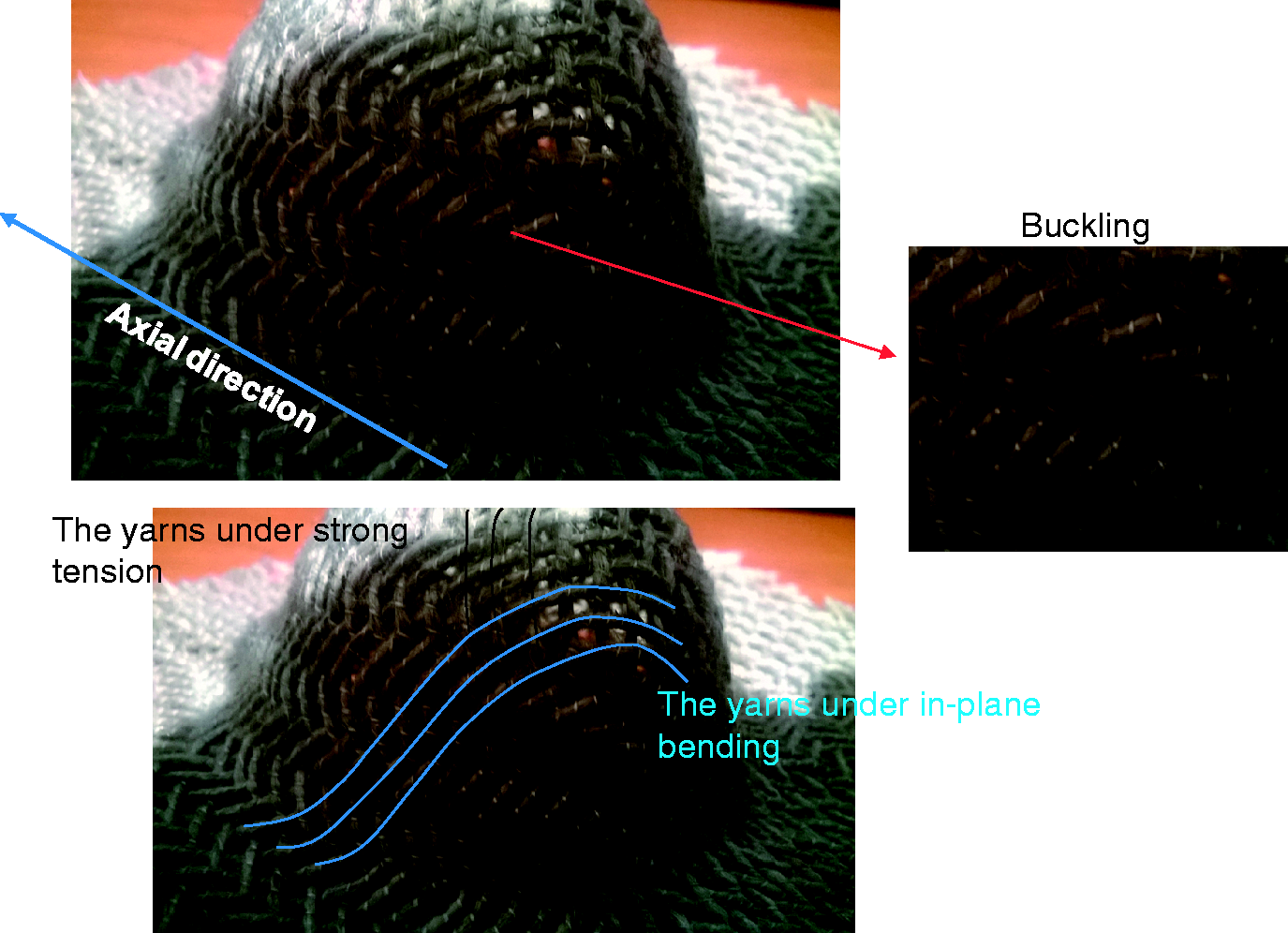
The preforming of the braided flax fabric corresponding to a 0.05 MPa blank-holder pressure is shown in Figure 7. The deformed shape is in symmetry to both axial and transversal directions. Two zones with big intraply shearing can be noted in the axial direction. This shear effect has an influence on the orientation of yarns after the preforming as represented in Figure 7. Consequently, the local fibre volume fraction in these areas is strongly modified and much higher than in the other areas in the useful zone (the hemispherical zone). Some undulated yarns can be observed due to the strong material draw-in through axial direction and no deformation in transversal direction. In the useful zone, the buckling phenomenon can be noted (Figure 8). As shown in the case of woven fabrics forming presented in Ouagne et al. [33], yarns in the transversal direction are submitted to a strong tension. The yarns in axial direction are subjected to in-plane bending which conduces to develop buckles. In order to minimize this defect, the blank-holder pressure is reduced to 0.01 MPa but the buckles are still observed in the hemispherical zone.
The deformed braided flax fabric after preforming. Buckling phenomenon noted in useful zone.
Material draw-in
As there is no deformation in transversal direction, the material draw-in through axial direction under different blank-holder pressure is shown in Figure 9. It is measured via pictures taken from a central point of view and perpendicular to the surface of the preform, sufficiently distant from it in order to reduce errors due to the shooting. The material draw-in is determined by 15 measurement points and the measurement precision is ±0.5 mm. The preforming test was repeated three times. A good reproducibility was obtained. Each curve in Figure 9 shows the mean value of the measurement data. The material draw-in curves have quasi symmetrical profile to the central measurement point (at 75 mm). When a weaker blank-holder pressure is applied on the fabric, a significant material draw-in can be observed. The maximum draw-in is not noted on the central measurement point (at 75 mm), but on the both sides of the central measurement point (at 55 mm and at 95 mm).
Material draw-in in axial direction of braided flax fabric under different blank-holder pressures.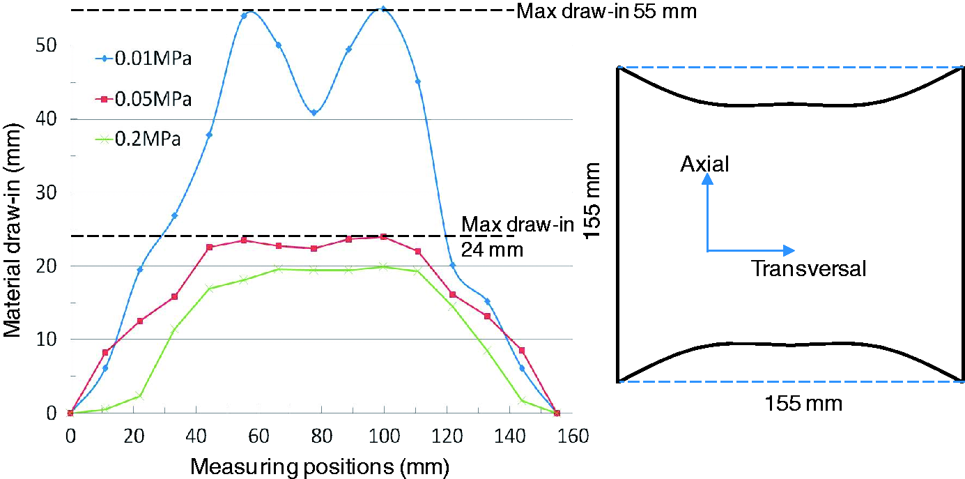
In-plane shear
In order to quantify the in-plane shear deformation, the angle between the yarns and the axial direction after forming (
β is braid angle, 35° in the present work.
Figure 10 presents a mean value of in-plane shear angle of the deformed braided fabrics under the blank-holder pressure of 0.05 MPa and 0.2 MPa (the measurement precision is ±0.5°). The measurement data presents the quasi-symmetric results to the point 0 (at the top of the hemisphere). The maximum shear zone can be noted in the diagonal direction (the blue region in Figure 10). In the useful zone, the more significant in-plane shear deformation can be observed when a higher pressure is applied on the blank-holder.
In-plane shear angle after forming of braided fabric under different blank-holder pressures: (a) 0.05 MPa and (b) 0.2 MPa.
Preforming of the woven fabrics
Preforming tests of the woven flax/polyamide fabrics under different forming conditions (different blank-holder pressures and different yarn orientations) are carried out. The deformed fabrics after forming with a 0.2 MPa blank-holder pressure are demonstrated in Figure 11. The deformed profiles are quasi-symmetry. No defects can be observed in the useful zone in both 0/90° and ± 45° deformed fabrics. The material draw-in and the in-plane shear will be analysed under each forming condition and then compared with deformed braided fabrics.
Experimental preforming of woven fabrics, the deformed 0/90° (a) and ± 45° (b) woven fabrics.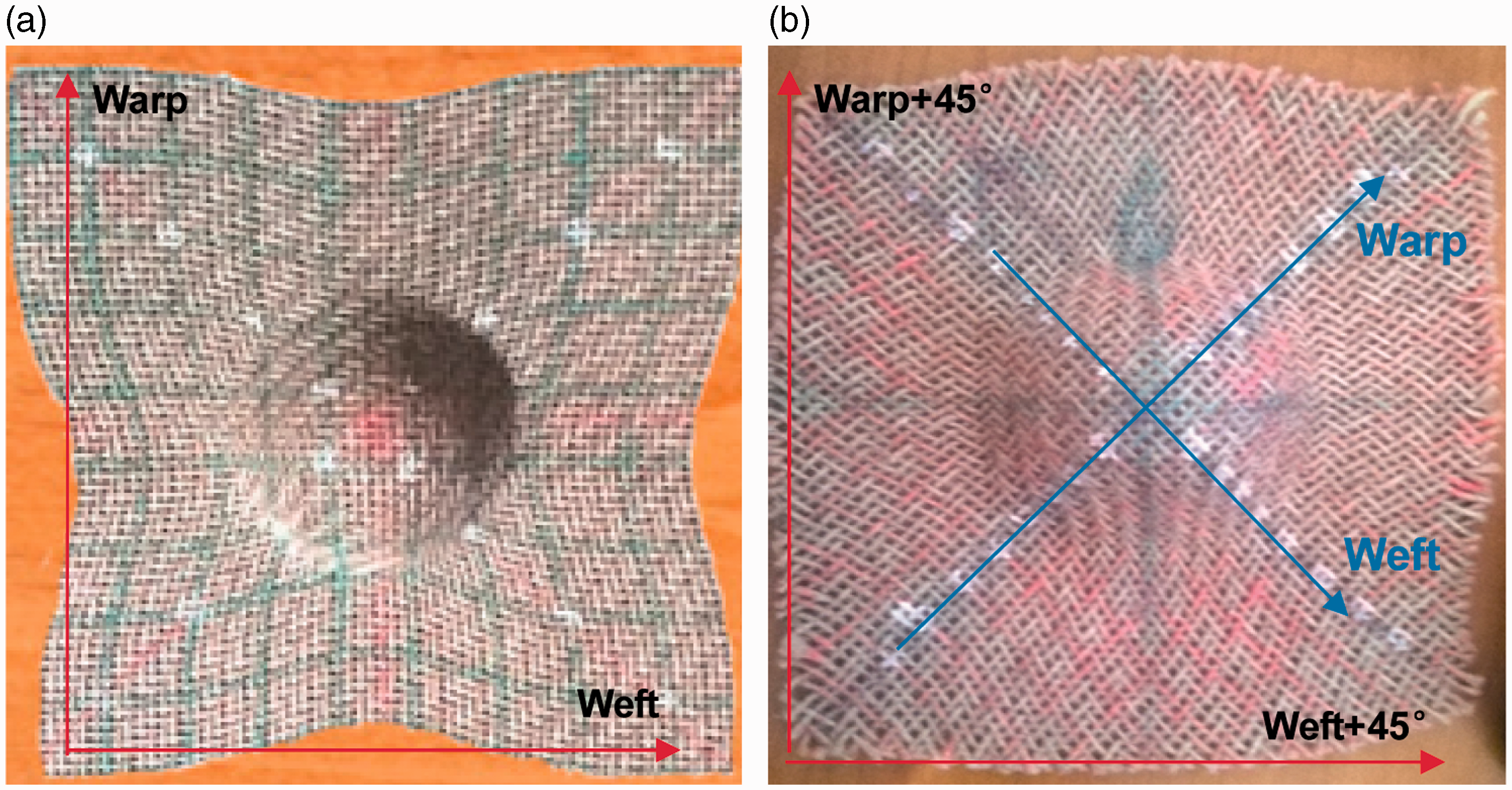
Material draw-in
Material draw-in in warp and weft directions of 0/90° woven flax/polyamide fabric under 0.05 and 0.2 MPa blank-holder pressures are shown in Figure 12. The measurement method is the same as the one used in the previous analyses. Each type of test was repeated three times and the mean measurement data was figured out. Every material draw-in curve is quasi-symmetric to the central measuring point (at 75 mm). The maximum draw-in is slightly higher in weft direction than in warp direction, but it stays in the range value of the standard deviation of measures. During the weaving the warp yarns were submitted to a more important tension and are more degraded than weft yarns. It probably leads to a difference of draw-in in the warp and weft directions. In the same yarns' direction, the more important draw-in can be remarked when a lower blank-holder pressure is applied. Furthermore, no draw-in can be observed on some measuring points in the case of a high blank-holder pressure (0.2 MPa). The link between the reinforcement's draw-in and the tensile behaviour in each direction is commonly studied. It can be noted that the tensile behaviour of the flax yarn presents a non-linear evolution and an important deformation at break [55] due to the constitution of flax yarns.
Material draw-in in (a) warp and (b) weft directions for the deformed 0/90° woven fabrics.
Figure 13 shows the material draw-in in warp+45° and weft + 45° directions for the deformed ±45° woven fabrics (see Figure 11) under different blank-holder pressures. The measurement data is globally symmetric. The maximum draw-in is slightly higher in weft+45° direction but stays in the range value of the standard deviation of measures. As presented previously, it is probably due to the degradation of warp yarns during weaving process. No material draw-in can be noted at the central measuring point. As for the forming of the 0/90° woven fabric, a higher draw-in can be obtained when a lower blank-holder pressure is used.
Material draw-in in (a) warp and (b) weft directions + 45° for the deformed ±45° woven fabrics.
In-plane shear
The in-plane shear angle fields of the deformed 0/90° and ±45° woven fabrics after forming are shown in Figures 14 and 15. These fields are generally symmetric to the point 0 (at the top of the hemisphere). The maximum shear zone can be observed on the edge of the useful region, in the diagonal direction for the deformed 0/90° fabric and in the longitudinal and transversal directions for the deformed ±45° fabric (the red regions in Figures 14 and 15). In both 0/90° and ±45° fabrics forming, the higher blank-holder pressure leads to a more important in-plane shear angle field. The maximum in-plane shear angle increases 3°–4° when the blank-holder pressure augments from 0.05 MPa to 0.2 MPa.
In-plane shear angle after forming of 0/90° woven fabric under different blank-holder pressures: (a) 0.05MPa and (b) 0.2 MPa. In-plane shear angle after forming of ±45° woven fabric under different blank-holder pressures: (a) 0.05 MPa and (b) 0.2 MPa.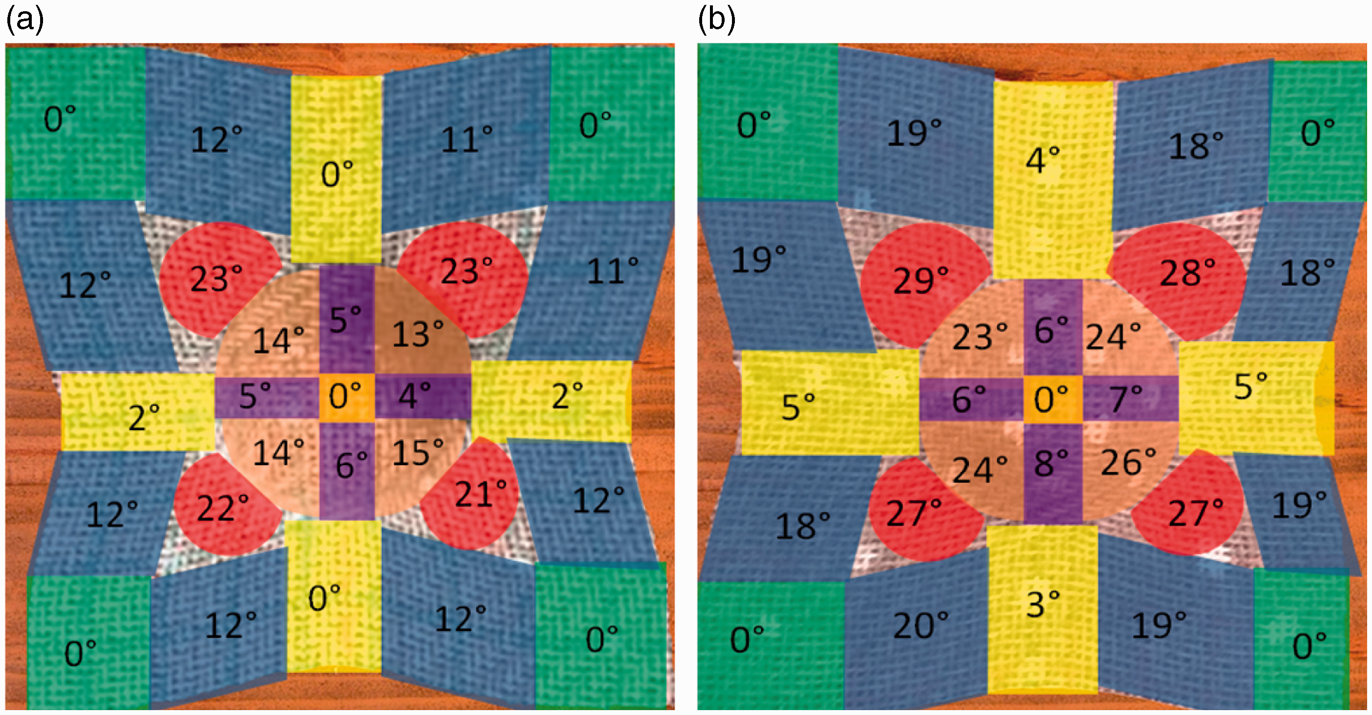

Comparison between the formability of braided and woven structures
The hemispherical preforming tests for the braided and woven fabrics are shown in the previous section (section ‘Results and discussions’). The braided and woven fabrics have been made of the same flax/PA12 commingled yarns and have almost the same area density, but the difference between braiding and weaving processes leads to two different textile structures, especially the angle between the yarns. Consequently, the different formability behaviours can be remarked during the preforming.
Compared to woven structure, the angle between the yarns of braids is different to 90°, it leads that the formability behaviour is very different between transversal and axial directions (no draw-in in transversal direction). The deformed fabric is characterized by a significant draw-in in axial direction and a strong tension is generated relatively in transversal direction. Hence, the buckles are developed in the useful zone. On the other hand, the tested woven fabrics (Twill 2-2) have a balanced structure. The deformed specimens present a symmetric profile and any defects cannot be observed during the forming step.
Regarding to the in-plane shear angle field, it is symmetry to the point at the top of the hemisphere in both braided and woven fabrics forming. As the extreme imbalance material draw-in is progressed during the braided fabric forming, the more important variation of the angle between the yarns can be noted in the useful zone. (e.g. under 0.2 MPa blank-holder pressure, the maximum variation of 64% for braided fabric and of 31% for woven fabric). Moreover, the angle distribution is different between the deformed braided and woven fabrics, especially in the zone at the top of the hemisphere (not equal to zero for the deformed braided fabric).
With the same nature of yarns and equivalent area density, the influence of the textile architecture, tested in this study during the preforming, is illustrated with the evolution of the punch force, which is monitored by a 500 N (±0.3%) load sensor (Figure 16). The force-time curves have a similar evolution. The punch force increases rapidly during the deformability of the fabrics and reaches a peak at the maximum punch displacement. After releasing certain efforts due to the effects of inertia displacement, a constant value of load to maintain the final shape of the deformed preform can be observed. It is obvious that the important punch force is obtained in higher blank-holder pressure. The initial orientation of yarns (0/90° compared to ± 45°) has an influence on the maximum punch force under a same blank-holder pressure. Furthermore, punch forces obtained in the forming of braids are always weaker than the ones obtained in the woven fabrics forming at the same blank-holder pressure. It confirms that the braided fabric is deformed more easily than the woven fabric (both 0/90° and ±45° fabrics). After the maximum punch force, a significant decrease of the force-time curves of braids can be observed. This phenomenon is probably associated to friction effects, where the peak is due to static friction of the fabric on the tool and the blank holder followed by sliding.
Punch force vs. preforming time for braided and woven fabrics.
Conclusion
In the present work, the preforming behaviour of dry braided reinforcements has been studied. In order to perform a comparison with the deformabilty of woven fabrics, the preforming tests of woven fabric samples, elaborated with the same comingled yarns and with equivalent area density to braided fabric, are carried out. To a classical hemispherical preforming the preliminary results demonstrate that the high deformability of braids leads to an important non-homogeneity in the in-plane shear angle distribution. Consequently, it seems more difficult to master the orientations of yarns in braided fabric forming. The variation of in-plane shear angle associated to the initial orientation of the yarns described by the braid angle leads to a different behaviour in the axial and transverse directions. It can be estimated by the analysis of material draw-in. In woven structures, buckles are developed during a complex shape forming, where yarns are submitted to high deformation in tension. The modification of blank-holder pressure can minimize this defect. In braided structures, the buckling defect even occurred during a simple hemispherical shape. Moreover, the increase of the blank-holder pressure leads to an increase of the in-plane shear and at the same time buckles are still present. In the forming of woven fabric, more pressure is applied on the blank-holder more tension is created in yarns. But in the forming of braided fabric, the effect of the augmentation of blank-holder pressure seems to involve an increase of the in-plane shear due to the high deformability of braids.
In future work, this experimental investigation will be continued firstly on simple geometry (hemispherical punch), but the braid angle will be changed. The effect of the orientation of yarns and the evolution of the in-plane shear angle will be compared between the braided fabric samples with different braid angles. The evolution of material draw-in along the axial and transversal directions will be analysed. As the double-curved shape forming is difficult to control and can lead to defects when the composite parts have high curvatures and large deformations, the deformability of braided fabrics during the forming by using more complex punch, such as the tetrahedral, the square box and the gusset structures will be studied, in particular the in-plane shear behaviour. In order to predict the feasible forming conditions, the aspect of numerical modelling and simulation of woven and braided reinforcements based on natural flax fibres forming need to be developed.
Footnotes
Acknowledgements
The supports from Schappe Techniques are gratefully acknowledged.
Declaration of Conflicting Interests
The author(s) declared no potential conflicts of interest with respect to the research, authorship, and/or publication of this article.
Funding
The author(s) received no financial support for the research, authorship, and/or publication of this article.