
Abstract
Thermal property of clothing has significant impact on thermal comfort of the wearers. In an extreme working condition body releases a lot of heat and sweat, in order to keep the body dry and at normal temperature these heat and sweat should be released in the environment. The thermal comfort of the fabrics mainly depends on how well it transmits heat and moisture to the environment. In this work finite element models have been developed to predict the thermal conductivity of plain weft knitted fabrics. Fabrics with different stitch density and yarn count were used in this work. A unit cell model of the fabrics was developed by using the actual geometrical parameters. Material orientation of the yarn was used for assigning the thermal conductivity of each element in the yarn. Boundary conditions were applied on unit cell of the fabrics for the determination of thermal conductivity. The geometrical models of the fabrics were generated by a plug-in which was developed in Abaqus/computer aided engineering using Python script. It has been found that thermal conductivity between the predicted results obtained from finite element analysis and experimental results from an in-house developed device is highly correlated. Furthermore, the application of geometrical model in different areas has been discussed, and technique is developed for the prediction of effective thermal conductivity of plain weft knitted composite fabric.
Introduction
The purpose of clothing is to maintain uniform body temperature under different level of activities and different environmental conditions [1]. Knitted fabrics have a good stretch property which offer better conformability and avoid excessive pressure between the garment and body [2]. Thermal comfort property of the textile fabric mainly depends on the heat and moisture transmission through the fabric [3]. Heat can be transferred by conduction from the solid fibres and entrapped air between the fibres, convection and radiation [4]. The thermal property of textile fabrics has been studied by different researchers. Baxter [5] measured the thermal conductivity of wool felt against different level of bulk density and moisture regain; he found that the thermal conductivity increases with the increase of bulk density and moisture regain. Matusiak [6] developed a model of thermal resistance of woven fabric as function of their structures. Ismail et al. [7] developed a theoretical model to predict the thermal conductivity of woven fabric.
Prakash and Ramakrishnan [8] studied the effect of blend ratio, loop length and yarn linear density on thermal comfort properties of single jersey knitted fabrics. It was found that the thermal conductivity of fabric decreases when the bamboo component in the yarn increases and also decreases as the yarn linear density increases because more air is entrapped in the yarn. The thermal conductivity increased with the increase of loop length. Fayala et al. [9] and Majumdar [10] developed an artificial neural network-based model to predict the thermal conductivity of knitted fabrics. Stankovic et al. [11] analysed the thermal properties of plain knitted fabrics made of natural and regenerated cellulose fibres. They concluded that the heat transfer phenomenon across the fabric depends on the air volume distribution within the fabric, capillary structure of component fibres and yarns, as well as yarn surface geometry. Oglakcioglu and Marmarali [12] analysed and compared the thermal properties of cotton and polyester-based single jersey, 1x1 rib and interlock knitted fabrics. They found that the thermal insulation properties of different structure depend on the amount of fibre per unit area. With the amount of fibre increases the amount of entrapped air decreases, therefore the thermal conductivity would be higher for thicker fabric.
Dias and Delkumburewatte [13] developed a theoretical model to predict the thermal conductivity of knitted fabric in terms of porosity, thickness and moisture content. They found that the thermal conductivity of knitted fabric increases with the increase of thermal conductivity of fibre and moisture content, and thermal conductivity also increases while the porosity of fabric decreases. Li et al. [14] reported that heat and moisture transport in porous textile material were significantly influenced by fabric thickness and porosity.
Ucar and Yılmaz [15] determined the natural and forced convection of rib knit fabric and also analysed the effect of fabric parameters on the thermal behaviour of fabric. Cimilli et al. [16] analysed the heat transfer of plain knitted fabric by finite element method, and their objective is to investigate the applicability of a finite element method (FEM) to textile problems. For that purpose they developed the model of weft knitted fabric and analysed it and compared with results from experiment.
In this work a geometrical model of weft knitted fabric was generated by using the plug-in developed in Abaqus/computer aided engineering (CAE) which is the first time to be done. The actual parameters of the fabric were taken into consideration. The thermal conductivity of the knitted fabrics was predicted by the finite element analysis and compared with the experimental results obtained from an in-house developed device.
Geometrical model
Many researchers such as Pierce [17], Hurd and Doyle [18], Shinn [19], Leaf and Glaskin [20], Leaf [21], Munden [22], Postle [23] and Kurbak [24] analysed the geometrical model of knitted fabrics. Demiroz and Dias [25] developed a mathematical model to generate three-dimensional (3D) images of plain weft knitted fabric. They developed a stitch model by using cubic spline as the central axis. Choi and Lo [26] developed a model of plain weft knitted fabric to describe the mechanical properties and dimensional change in a fabric. Kyosev et al. [27] developed two models of plain weft knitted fabrics. Their first model is pure geometrical model based on the geometrical model of Choi and Lo [26] by considering the yarn cross-section as elliptical. Their second model was based on the discretization of yarn into small element and also considered mechanical interaction between the yarns.
Specifications of plain weft knitted fabrics.

MF: monofilament; MFF: multifilament; SF: staple fibre.
Thermo-physical properties of fibre [28].

Plug-in of plain weft knitted fabric
There are software available such as TexGen [30], TexEng [31], WiseTex [32], etc. which have been used to generate 3D geometric models of plain weft knitted fabrics. However, they can only generate weft knitted structures in their own environment, and the generated geometric models have to be imported into other finite element analysis software as part or model. In this work Abaqus/CAE which is a powerful software for solving linear and non-linear engineering problems using finite element method was employed as a platform. It has been used for impact, heat transfer, computational fluid dynamics and mechanical (static and dynamic) analysis of complex textile structures. A plug-in was developed and can be used to generate weft knitted fabric geometry in Abaqus environment. The weft knitted fabric geometry generated can be directly used for finite element analysis (FEA) in Abaqus, which is very user friendly. A geometrical model of plain weft knitted fabric created by the plug-in developed in Abaqus/CAE is shown in Figure 1.
Main interface of plug-in for plain weft knitted fabric and highlighted three options for model generation.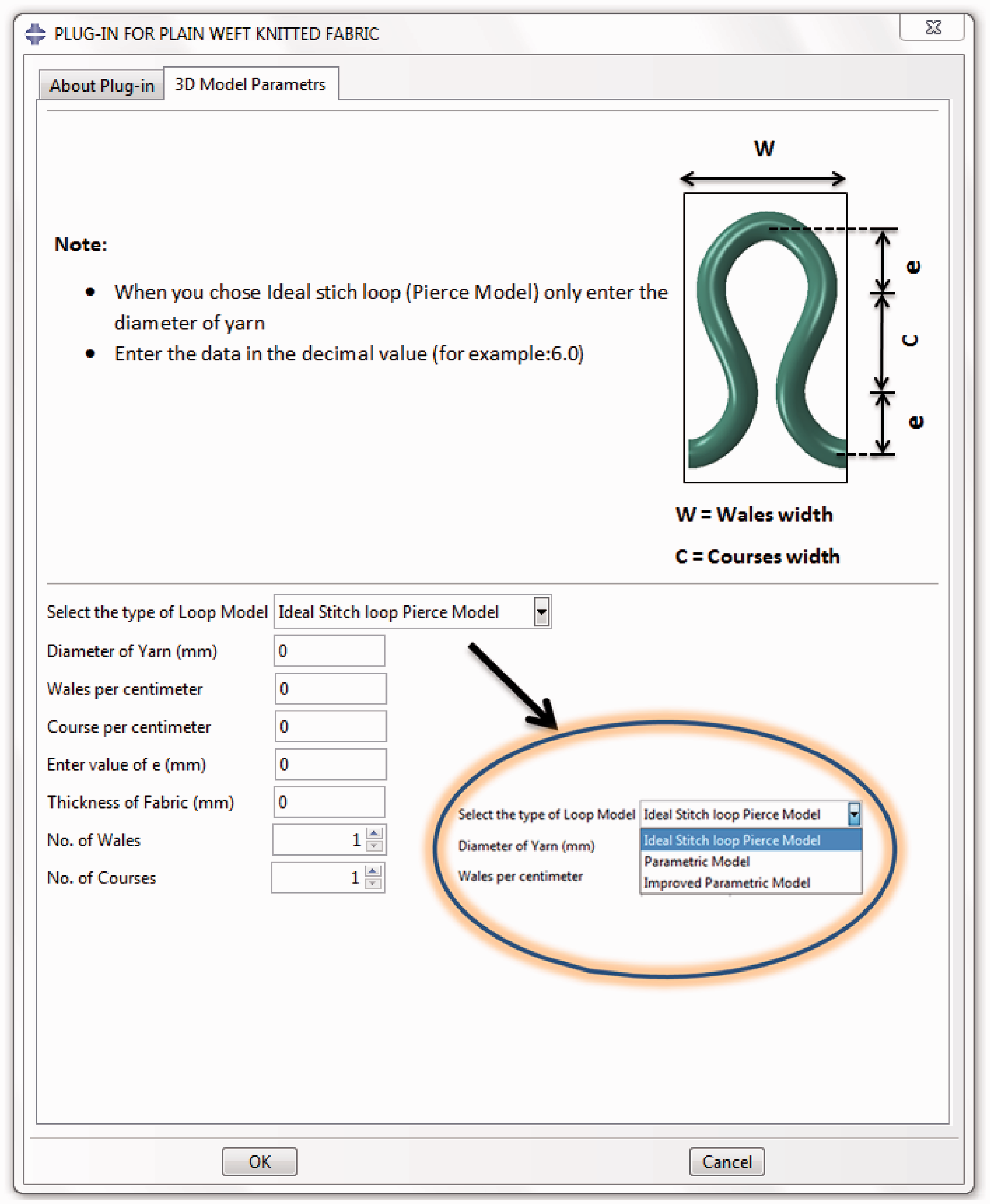
The main objective of the developed plug-in is to provide a graphical user interface to enable automatically generating 3D models of plain weft knitted fabrics with only few necessary input parameters. These models can be used to predict the porosity, shrinkage, compression and elongation behaviour of plain weft knitted fabric and composites. There are three options in geometric model creation in plug-in, shown in Figure 1.
An ideal stitch loop Pierce model [17] is created by considering the relations of stitch length, course and wales spacing which are derived from Figure 3(a). If ‘d’ is the diameter of yarn, course spacing can be calculated by
(a) geometry of plain weft knitted structure and path of yarn central axis by pierce, (b) yarn central axis defined in plug-in, and (c) thickness of fabric. Geometrical model of fabric F3.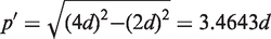


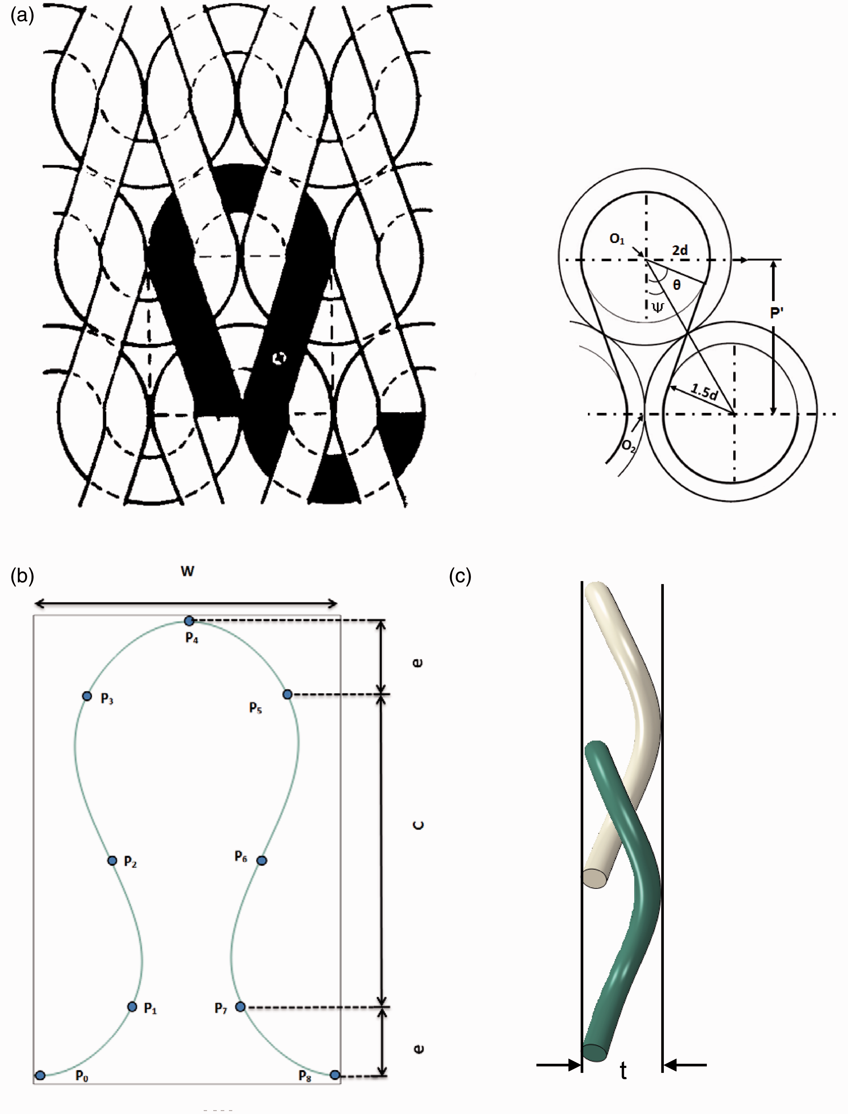

The points illustrated in Figure 2(b) were calculated by the above equations which define the central axis of yarn using cubic spline curve in Abaqus/CAE. The 3D models of plain weft knitted fabrics can be generated by sweeping the circular cross-section of the yarn along the central axis of the yarn. Yarns were assumed to be incompressible in nature.
If an ideal stitch loop Pierce model is selected then only diameter of yarn (d) is required to generate the geometric model of plain weft knitted fabric; it can be calculated by the following equation

In parametric model of plain weft knitted fabric, the central axis of yarn is defined by the same path shown in Figure 2(b) but the actual parameters of the fabric such as courses and wales per centimetre were used. Parameter ‘e’ can be determined by the average loop height (H) through image analysis using the following equation

In modified parametric model, a factor γ [33] was introduced to reduce the yarn intersection, shown by the following relation

A polyester plain weft knitted fabric (F3) model generated by the plug-in is shown in Figure 3.
Effect of parameter ‘e’ on loop structure of fabric F3. (a) At e = 0.2, (b) at e = 0.3, (c) at e = 0.4245, and (d) at e = 0.5.
Effect of ‘e’ value on loop structure
In Figure 4 the effect of ‘e’ value on loop structure of fabric F3 was analysed by increasing and decreasing the ‘e’ value from the actual value of 0.4245. It can be observed clearly that when the value decreases loops become more compact and loop length decreases or vice versa.
Material orientation.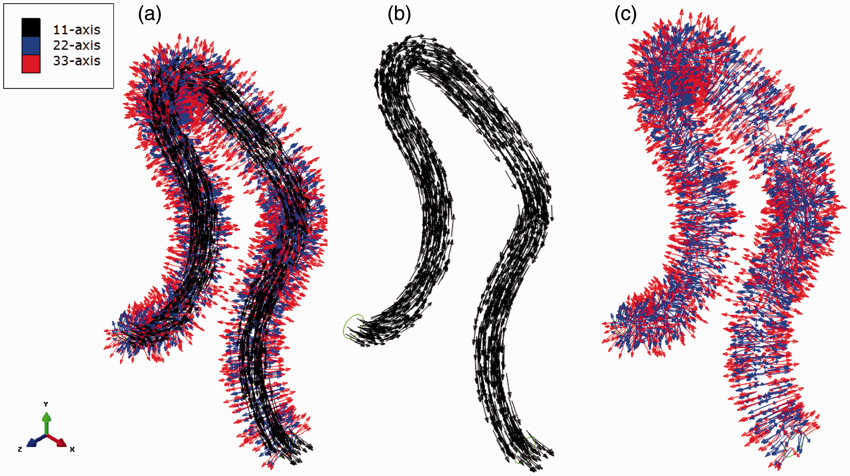
Material orientation
Material of yarn is considered as solid orthotropic with the consideration of transversely isotropic. Transversely isotropic materials are those which have the equivalent physical properties at every point in the material about an axis that are normal to the plane of isotropy.
Figure 5(a) shows the material orientation achieved in Abaqus/CAE, 11-axis refers to the axis which is parallel to fibre axis, 22 and 33-axis are transverse (perpendicular) to the fibre direction. Figure 5(b) and (c) shows the fibre direction only along the fibre axis and transverse to the fibre direction, respectively. Material orientation in Abaqus/CAE is defined by discrete orientation method. A discrete orientation defines a spatially varying orientation at the centroid of each native or orphan mesh element. The orientation is based on the topology of the part, allowing defining a continually varying orientation. Once the normal axis and a primary axis are defined, Abaqus/CAE uses these axes to construct a right-handed Cartesian coordinate system [34]. For that purpose the surface of the yarn is divided into small faces by partition and the edges and surfaces are selected for primary and normal axis, respectively.
Thermal conductivity of a yarn can be defined by

Yarn packing/volume faction (Vfy) for fabric F4 and F5 can be calculated by equation (5) which are 0.213 and 0.274, respectively.
Thermal conductivity of the yarn along the fibre axis (kya = K11) for fabric F4 and F5 can be calculated by the rule of mixture as shown in equation (9)

Thermal conductivity of yarn along the transverse direction (Kyt = K
22
= K33) for fabric F4 and F5 can be calculated by series, Clayton [35] and Pilling [36] model as shown in equations (10) to (12)


Thermal conductivity of yarn of F4 and F5.

Calculated by series model.
Unit cell
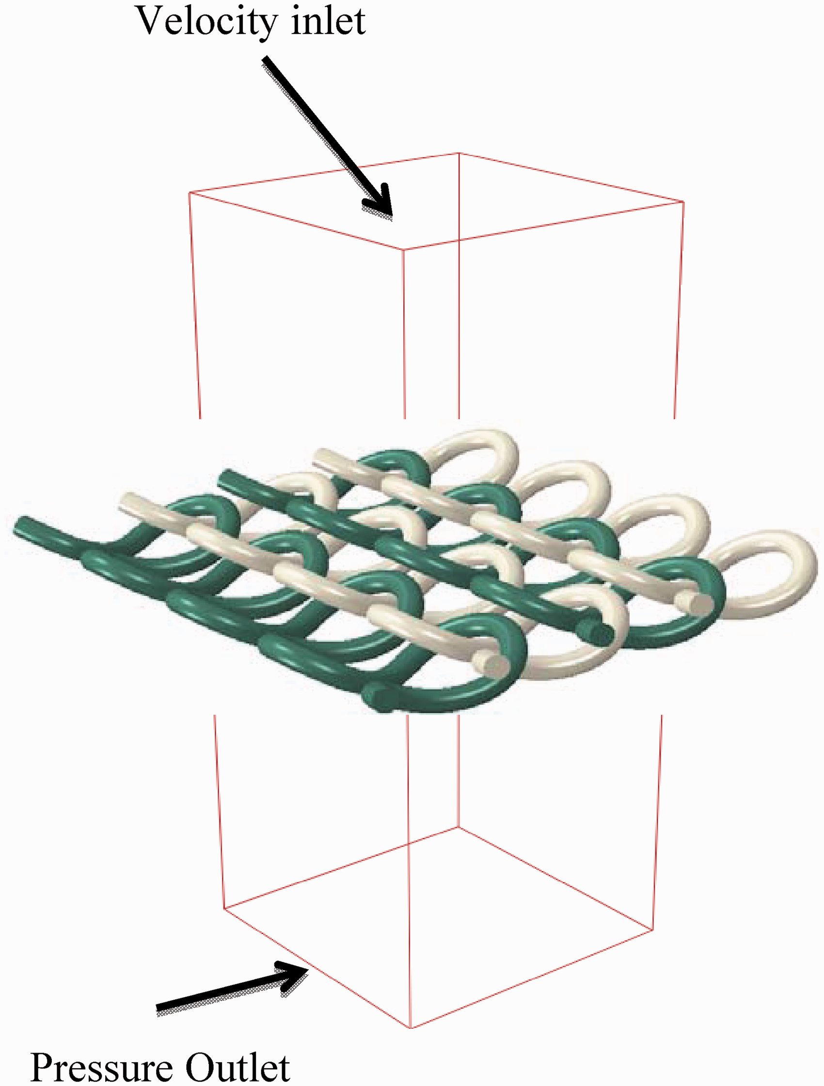
Figure 6 shows the unit cell model used to analyse the thermal conductivity of plain weft knitted fabric. Three types of model were developed for analysing the thermal conductivity of fabric. In model 1 material orientation of yarn was considered as described in ‘Material orientation’ section. In model 2 global material orientation was considered and in model 3 fibres were considered as isotropic in nature.
Unit cell model of fabric F3.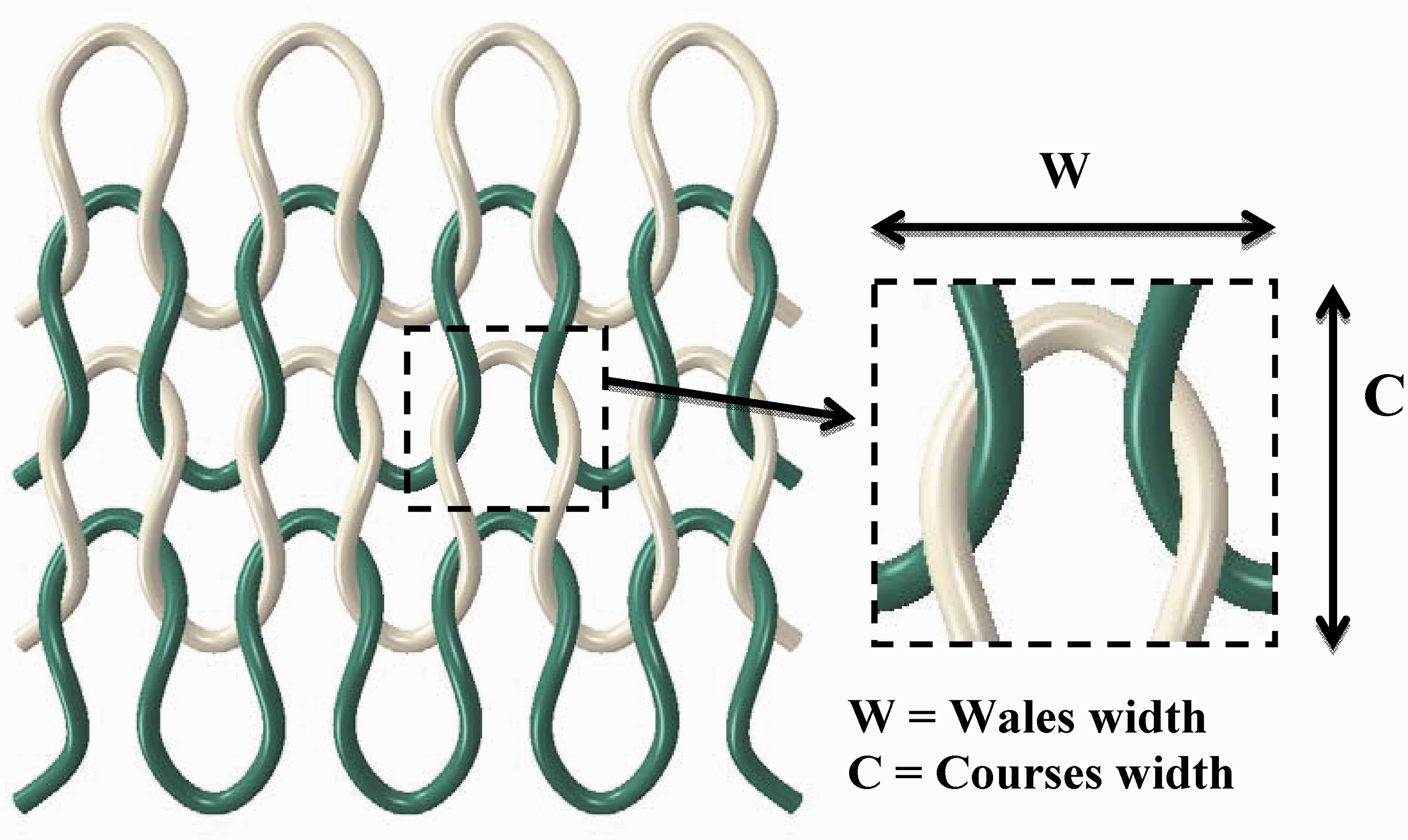
Analysis
Figure 7 shows the unit cell model consisting of a hot and cold plate, an unit cell of weft knitted structure and entrapped air. The following assumptions were made to the model:
Consider air as fluid matrix; Neglect the effect of radiation and convection; There is no compression of fabric between the plates. Unit cell model for analysis.

Effective thermal conductivity of unit cell model can be calculated by

Table 4 and Figure 8 show the effective thermal conductivity obtained from the simulation of plain weft knitted polyester fabric. Model 1 shows the higher values of effective thermal conductivity as compared to model 2 and 3. In model 3 there is no consideration of anisotropy characteristics of the fibre. It means that heat flow takes place in transverse direction only and there is heat flow in axial direction. Therefore the effective thermal conductivity is the lowest for model 3.
(a), (b), and (c): Heat flux contour of model 1 unit cell fabric F3; (d), (e), and (f): Temperature contour model 1 unit cell fabric F3. Effective thermal conductivity from FEA.

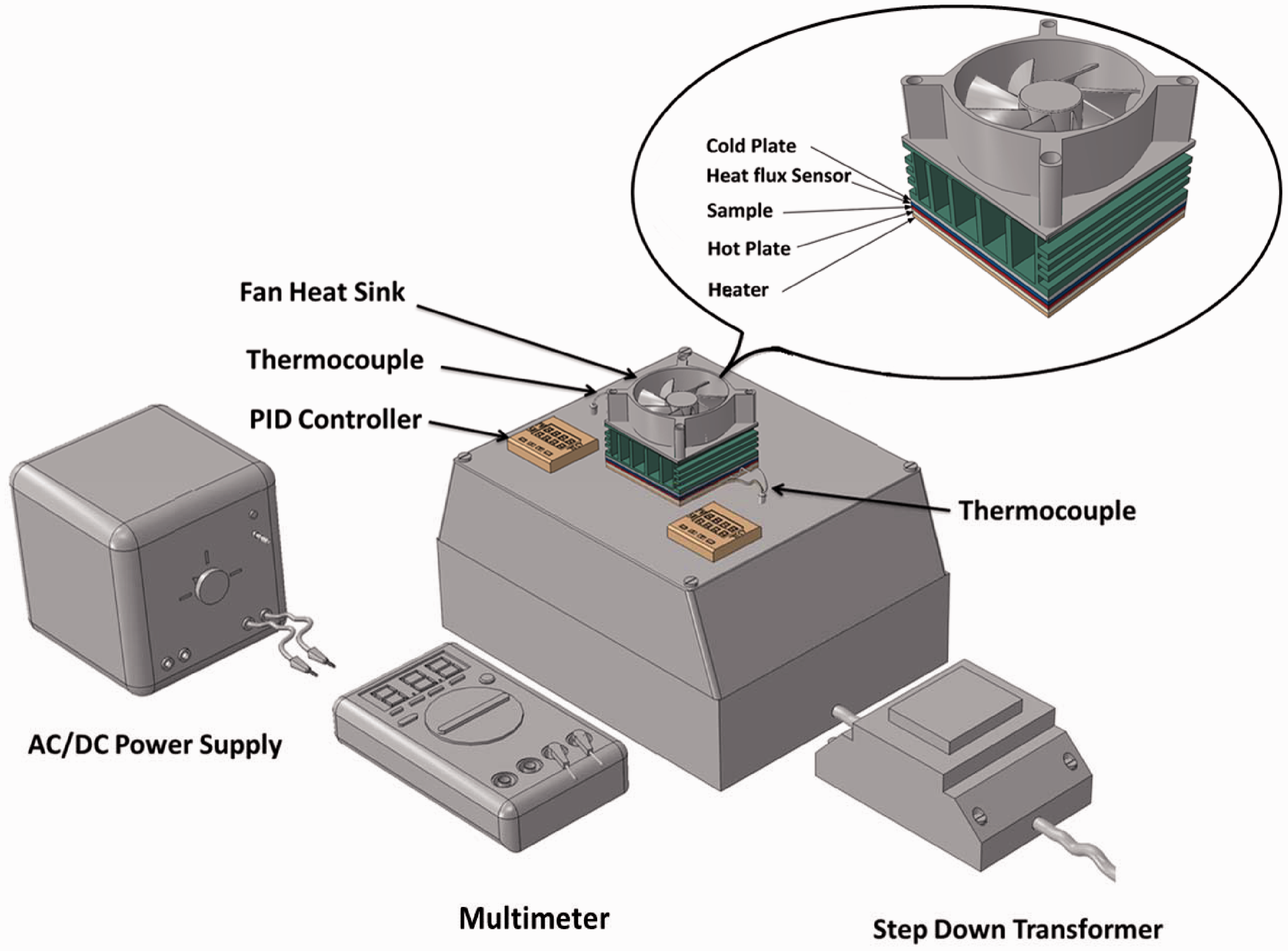
Experimental setup
In order to validate the results obtained from the model, test was conducted on an in-house developed device for thermal conductivity test as shown in Figures 9 and 10. It works on the principle of two plates (hot and cold) providing an initial environment with temperature difference between the two surfaces of a fabric to be tested. Fabric sample is placed between the hot and cold plate. The hot plate is heated by a proportional-integral-derivative controller with predetermined temperature. The temperature of the cold plate is controlled by a fan heat sink. A heat flux sensor with sensitivity of 16.8 µV/(W/m2) is used with cold plate to measure the amount of heat flow through the sample because of temperature difference. Temperature sensors are connected with hot and cold plates to measure the temperature difference across the sample. Thermal conductivity of the sample is calculated by the following equation
Experimental setup. 3D model of experimental setup.

Experimental results of effective thermal conductivity.

Application of geometric model
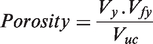
Geometrical model can be used to determine the porosity of plain weft knitted fabric as shown in equation (15)
The porosity of plain weft knitted values can be calculated by Dias and Delkumburewatte [13] theoretical model as shown in equation (16)

Porosity of plain weft knitted can also be calculated by equations for porosity of solid material in terms of percentage as shown in equation (17) [38]

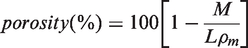
Table 6 presents the volume of yarn and unit cell. Table 7 and Figure 11 show the comparison between the porosity obtained from the models created from plug-in and other method. It is obvious that the results obtained are very close to each other; this means that the models made by plug-in are reliable and can be used for FE analysis.
Comparison of porosity between plug-in and other methods. Yarn and unit cell volume. Comparison of porosity between plug-in and other method. Thermal conductivity of epoxy resin and E-glass fibre.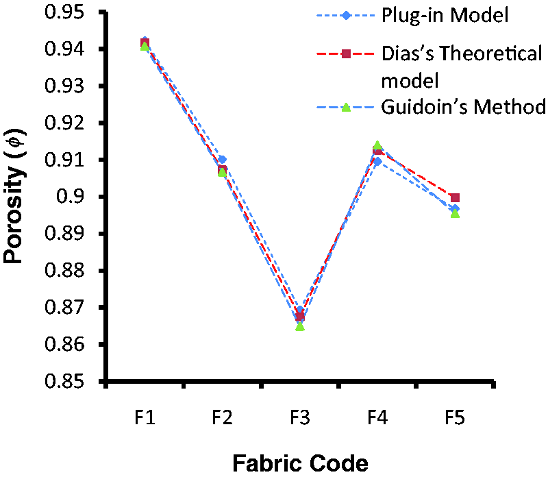


It can also be used for prediction of permeability of plain weft knitted fabric made of untwisted and twisted multifilament yarn as shown in Figure 12(a) and (b) by the method which was described by Wang et al. [39], shown in Figure 13. Geometrical model can also be utilized for the determination of mechanical properties of plain weft knitted composite fabrics discussed by Ramakrishna [40] using finite element method as shown in Figure 14.
Knitted loop with (a) untwisted multifilaments and (b) twisted multifilaments. Simulation setup for permeability of plain weft knitted fabric. Finite element model of plain weft knitted composite fabric.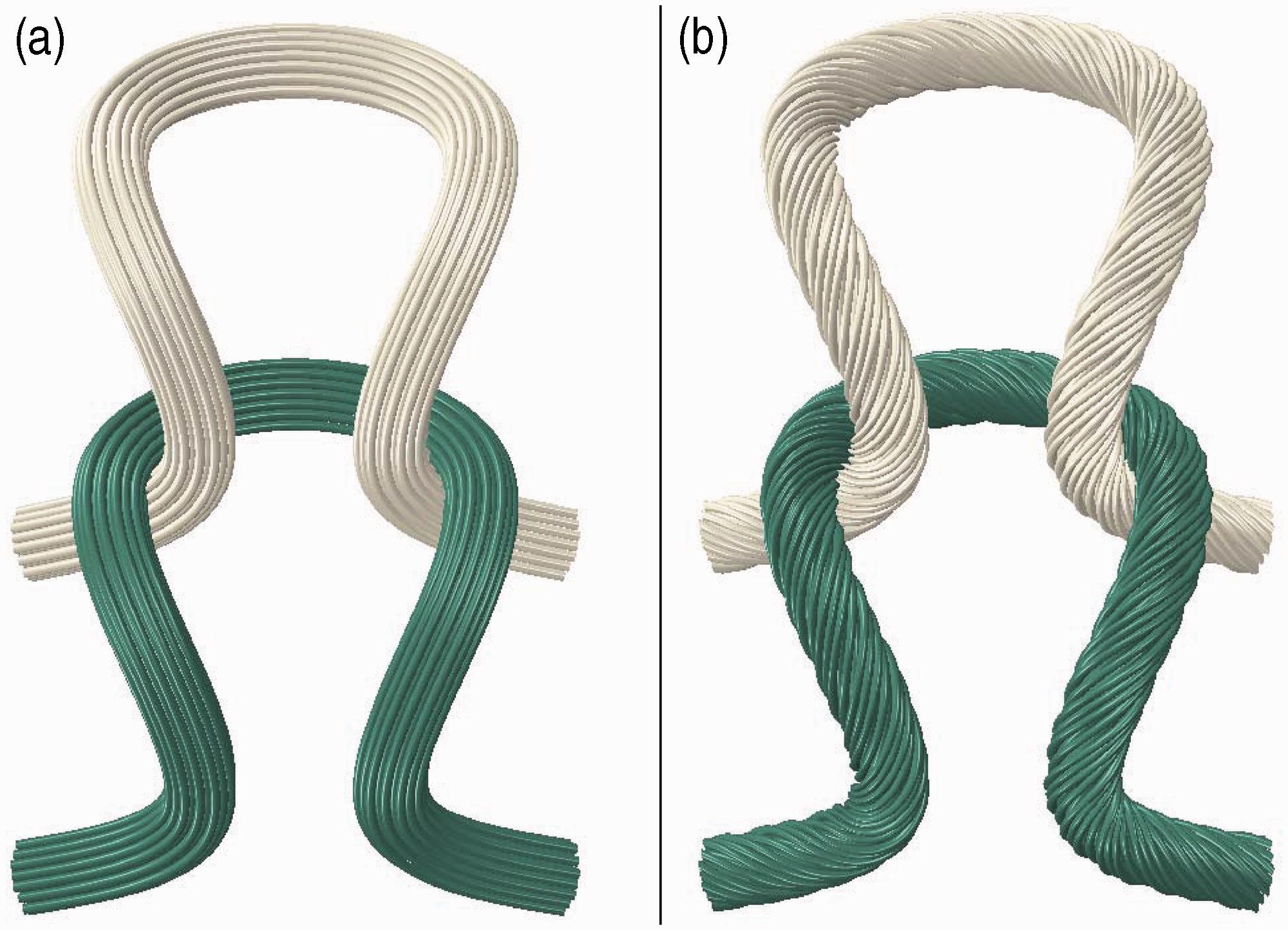

A method is developed to determine the effective thermal conductivity of plain weft knitted composite fabric, by considering the same fabric construction specification of F3 with the amendment of fibre and matrix material. E-Glass fibres with FR-4 epoxy resin material were assumed for the analysis. Yarn is considered as porous material and the fibre volume/packing fraction of yarn (Vfy) can be calculated by
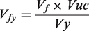
Table 8 presents the thermal conductivities of epoxy resin and E-glass fibre.
Thermal conductivity of the impregnated yarn along the fibre axis (kya) can be calculated by the rule of mixture as shown in equation (9).
Thermal conductivity of impregnated yarn along the transverse direction (Kyt) can be calculated by series model, Clayton [35] and Pilling [36] model as shown in equations (10) to (12).
Effective thermal conductivity at different fibre volume fractions.
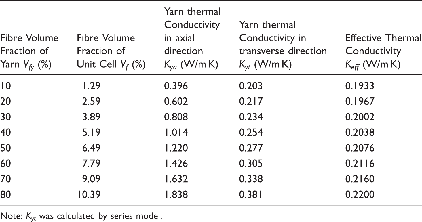
Note: Kyt was calculated by series model.
Figure 15 shows the effective thermal conductivity of plain E-glass/epoxy weft knitted composites. The thermal conductivity increases with the increase of fibre volume fraction.
Effective thermal conductivity at different Vf.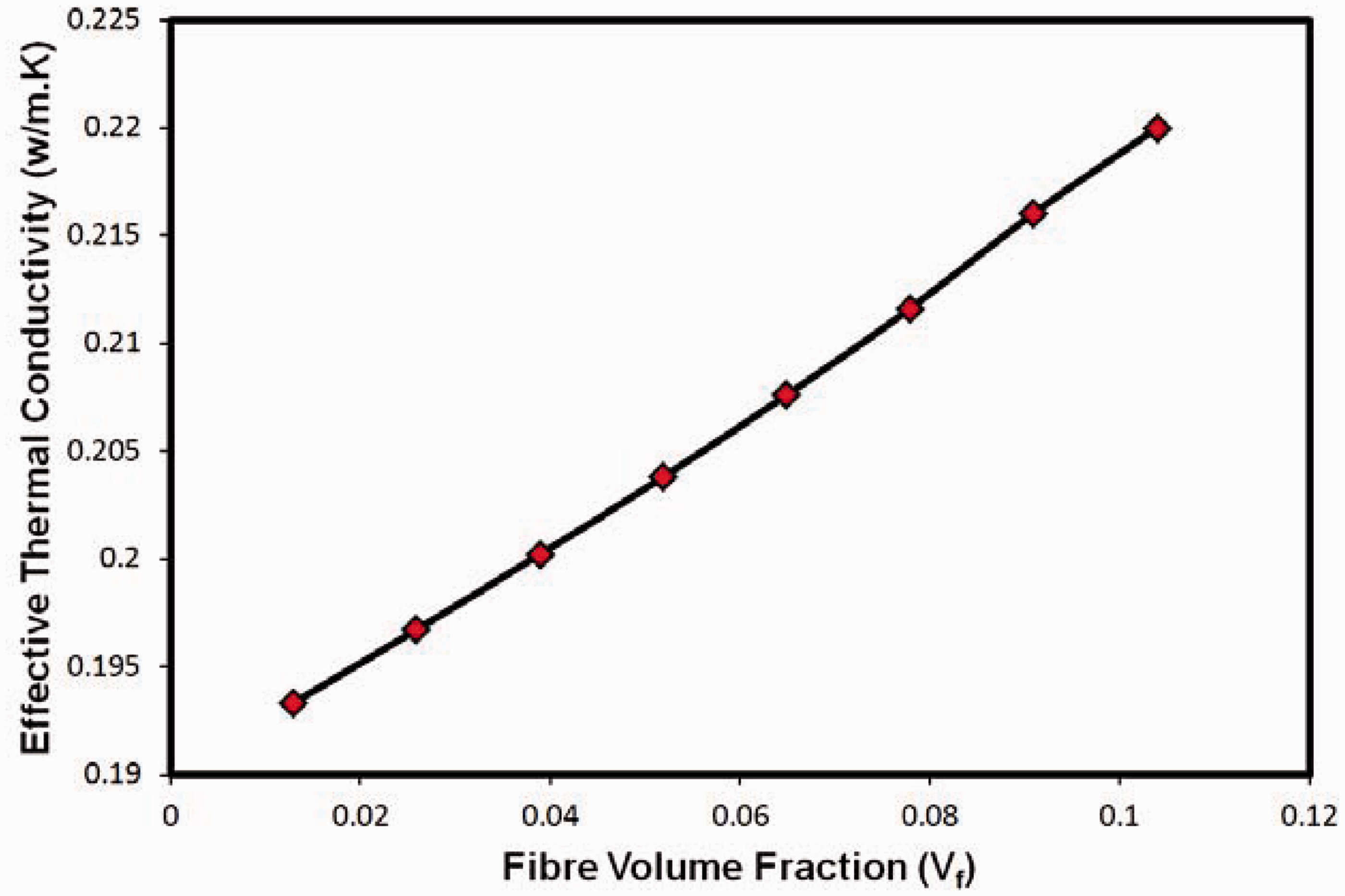
Results and discussion
Comparison of mean absolute error (%) of the effective thermal conductivity between results from models and experiment.

Model 1 shows less error as compared to the other two models. Model 1 considered the nature of fibre material as anisotropy as well as actual fibre orientation. There was no consideration of actual fibre orientation in other two models, especially in model 3 fibres are considered isotropic in nature. The correlation coefficient between experimental and predicted values was found to be 0.840.
Conclusion
A user friendly plug-in was successfully developed using Abaqus/CAE as a platform. It can be used to generate geometric models of plain weft knitted fabrics. The generated geometric models by plug-in can be directly used in Abaqus for FE analysis.
Three FE models with different consideration of fibre orientation and anisotropy of fibre have been studied based on the geometric models created by plug-in. The main findings of the research work are as follows:
Material orientation has significant effect on the effective thermal conductivity of plain weft knitted fabrics due to the effective thermal conductivity obtained from model 1 which was able to produce the closest results to the experiment. Anisotropy value of thermal conductivity of fibre affected the effective thermal conductivity of fabric. Plug-in is able to generate reliable geometrical models of knitted fabrics because it predicts the porosity values which are very close to previously established method for the determination of porosity of plain weft knitted fabrics.
A strong correlation coefficient and less absolute mean error percentage show that the models created from the developed pug-in are capable of predicting the effective thermal conductivity of plain weft knitted fabrics for finite element analysis.
Footnotes
Declaration of Conflicting Interests
The author(s) declared no potential conflicts of interest with respect to the research, authorship, and/or publication of this article.
Funding
The author(s) disclosed receipt of the following financial support for the research, authorship, and/or publication of this article: This research is financially supported by NED University of Engineering and Technology, Karachi, Pakistan.