
Abstract
In literature, there exist many investigations about the application of knitted textiles as a reinforcement material in composites. Although majority of them are mainly centered on flat plates, tubular knitted fabric is used in current study to develop composite pipes. Produced composite pipes are subjected to axial compression before and after 5J impact test. Force–time and force–displacement curves are obtained, and compression stress is calculated according to wall thicknesses of the pipes. It is observed that the interlacing of yarns in knitted tubular fabric through the thickness direction increases the splitting toughness of composite pipes. Although the compression failure takes place as buckling in both nonimpacted and impacted composite pipes, damage propogation in the transverse direction is not observed. The results of the study are presented in detail.
Introduction
Composite pipes are widely used in many engineering applications including aerospace, automotive, infrastructure, pressure tank, mainly in oil and natural gas industry due to their improved properties, ranging from weight reduction to increased strength and durability features [1]. Composite pipes reinforced with organic or inorganic fibers in polymeric matrix are becoming more popular due to their high stiffness and lower weight and are manufactured by molding, casting, and pultrusion techniques [2]. On the other hand, filament winding has emerged as the primary process for thermoset composite pipes and cylindrical structures fabrication at low cost [3,4]. In this process, composite reinforcements (filament, wire, yarn, tape, or other) are usually made up of glass, and Kevlar or carbon are wound on a rotating mandrel [3]. Composite pipes and cylindrical structures have attracted attention of many authors. Mertiny et al. [4] produced tubular composite structures by multiangle filament winding and compared them with a baseline configuration in terms of stress at failure and stress–strain curves. They concluded that multiangle-winded composite structures provided considerable advantages over pure angle ply layup ones. Onder et al. [5] designed optimal angle ply orientations for filament wound composite pressure vessels and examined the maximum burst pressure. Gning et al. [6] investigated quasi-static and impact indentation behaviors of filament wound glass epoxy tubes. They found that 4 J impact energies involve delaminations with debonding of all the interfaces, and at higher energies, these delaminations propagate and are accompanied by the multiplication of intralaminar cracks. Saito et al. [7] studied energy absorption properties and fracture mechanisms of pultruded fibre reinforced square tubes. The authors characterized the crushing morphology of these tubes as brittle buckling that propagated cracks longitudinally.
The adaption of 2D or 3D textiles has also potential in reinforcement of composite pipes or cylindrical structures. The 2D or 3D textile reinforcements can be manufactured by weaving, braiding, knitting, and stitching. In the current study, a comprehensive literature survey was made, and it was observed that braiding seems to be the most focused structure for composite pipe reinforcement. Calme et al. [8] focused on evaluating energy absorption and mechanical behavior of 3D braided composite rings and used resin transfer molding to produce 3D textile-reinforced carbon/epoxy cylinders. Microscopic observations of damage evaluation showed the absence of delamination owing to 3D reinforcement architecture. Hufenbachb et al. [9] used braided textiles in order to produce composite tubular samples by winding method and conducted experimental tests by applying uniaxial loads. Nasu et al. [10] fabricated four kinds of braided rectangular pipes with different braiding angle and performed three-point bending test. They found that the bending moduli and the bending strengths for each specimen decreased with an increase in the braiding angle. Zsigmond et al. [11] described the main steps of a new method for the electron beam production of closed profiles made of carbon fiber-reinforced composite by braiding. The authors showed that not only the high modulus of elasticity but also the better behavior is characterizing the new braided carbon fiber composite.
Knitted textiles may also have a potential for the reinforcements of composite pipes. Actually, studies about knitted fabric composites began in the 1961 by Marvin, and since then, these materials have attracted increasing attention because of their probable uses and advantages [12]. Although most of the existing literature about knitted textile-reinforced composites mentioned near net shape manufacturing capability, in other words, orientation to complex shapes of knitted preforms [13–17], majority focused on composite plates. Composites developed by using shaping capability of knitted fabric reinforcements include fairings for aerospace applications, medical prostheses, exhaust guide vane, and a cycling helmet for competitive sports [18]. Composite pipes may be a good application area for these structures, but there are very limited studies which used knitted structures in the reinforcement of these composites. Ramakrishna and Hull [19] discussed the effects of fiber architecture and fiber content on the energy absorption capability of epoxy composite tubes reinforced with knitted carbon fabric. Statler and Breay [20] developed a composite tube for fluid delivery system which comprised a tubular arrangement of knitted fiber, and resin material was applied by vacuum bagging process.
With respect to the literature review given above, the importance and diversity of the current study can be summarized as follows. Despite the shaping capability of knitted fabrics, published works were generally focused on the reinforcement of composite plates. This study focuses on the production of composite pipes from tubular knitted fabrics by benefiting their near net shape manufacturing capability. There exist very limited investigations about the composite pipes reinforced with tubular knitted preforms. However, in this study, tubular knitted fabrics were produced from Kevlar and carbon yarns. These tubular textiles used in the reinforcement of thermoset composite pipes. Moreover, to the best of author’s knowledge, this is the first study where conventional filament winding method and its instruments are employed in the production of knitted fabric reinforced composite pipes.
Materials and methods
Production of tubular knitted preforms
Physical and mechanical properties of preforms and codes of composite pipes.
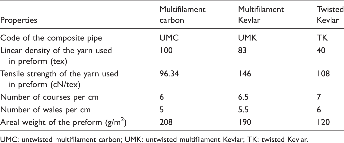
UMC: untwisted multifilament carbon; UMK: untwisted multifilament Kevlar; TK: twisted Kevlar.
Tubular fabrics (single jersey knitted) were manufactured using these yarns, by 3.5″ diameter, 7 E circular knitting machine. In order to get equivalent stitch lengths, all knitted preforms under study were produced from each yarn type with the constant knitting parameters. During knitting, no visible fiber damages were seen in Kevlar fibers while some fiber breakages were observed in carbon. Totally, three types of knitted fabric preforms were produced. Areal weights of the ultimate preforms were evaluated according to ASTM-D 3776 [23], and the results are given in Table 1.
Production of composite pipes
Dissociative was applied on the metal mandrel having a 73 mm diameter. Then, the first layer of tubular knitted fabric preform was not winded but passed on the mandrel and painted with the resin bath containing EPON™ 825 resin and EPON™ 875 hardener. This process was also repeated for other two layers of preform. After all, shrink tape was wrapped all over the last layer. In the next step, components were cured on the mandrel in an oven at 120°C for 4 h. While curing in the oven, the pipes were rotated to maintain even distribution of the resin, and after 4 h, they were allowed to cool down to room temperature. Finally, specimens were extracted from the mandrel and cut into 150 mm length by means of diamond wheel saw. Attention was paid during the specimen cutting, to ensure flat and smooth surfaces, free of burrs. Due to fibers’ different linear densities, the specimens’ wall thicknesses were 1.70 mm, 1.55 mm, and 1.19 mm for untwisted multifilament carbon (UMC), untwisted multifilament Kevlar (UMK), and twisted Kevlar (TK) pipes, respectively. All of the specimens had same inner diameter, 73 mm (Figure 1(a) and (b)). Average fiber weight fractions were 25%, 19%, and 17%, for UMC, UMK, and TK composite pipes, respectively.
(a) Carbon composite pipe, (b) Kevlar composite pipe, and (c) impact specimen with the apparatus.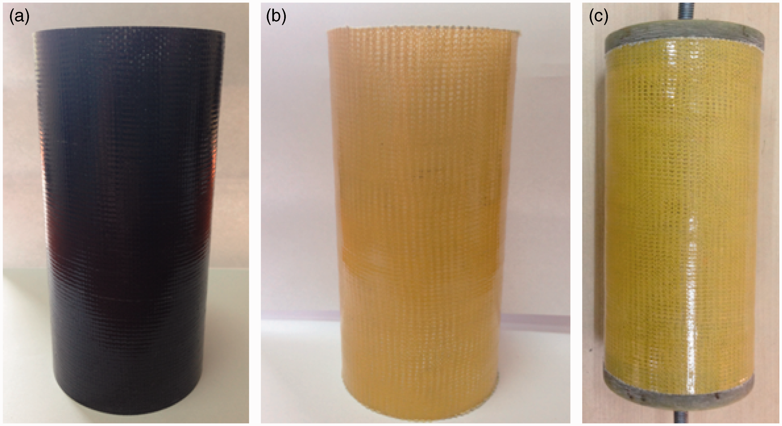
Experimental procedure
From each pipe, five specimens were subjected to the low velocity impact by using Fractovis Plus test machine. The impact velocity was held approximately 1.42 m/s, and total mass of the impactor was fixed at 4.92 kg resulting in a kinetic energy of 5 J. The energy value used in this study was determined by preliminary tests. The impactor had a hemispherical nose of 12.7 mm diameter. For each impact event, force time and force deflection graphs were plotted by the software, and parameters such as peak force, maximum deflection, and velocity were calculated.
Specimens were subjected to low velocity impact test by closing their open ends by a special apparatus which was developed by Deniz et al. [24] (Figure 1(c)). This method was used in order to simulate real impact behavior of a long pipe [24]. Specimens were fixed to V groove apparatus by two U bolts during impact to give the highest rigidity (Figure 2).
Placement of specimen in impact test machine.
Shimadzu testing machine was used to apply axial compression to the nonimpacted and impacted pipes. All tests were performed with a constant crosshead speed equal to 2 mm/min. Force–displacement curves were recorded and maximum loads were calculated through a data acquisition system. In order to avoid the failure in the contact point of pipe ends and head of the compression test machine, the pipes were closed with two end caps (Figure 3). Totally, five specimens were tested from each impacted and nonimpacted pipe.
Placement of impacted specimen in compression testing machine.
Results and discussion
Using the data obtained from the impact and compression tests, the one-way analysis of variance test is performed. Since p values are found to be less than 0.01, it can be said that the pipe type significantly affects impact and compressive strength at the 99% confidence level.
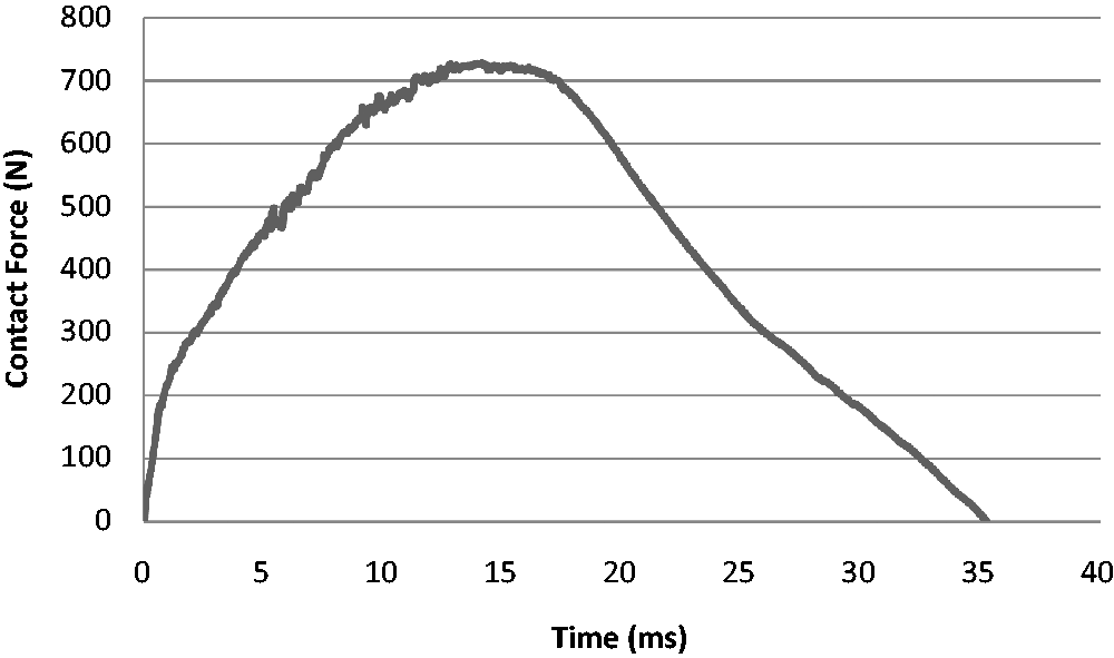
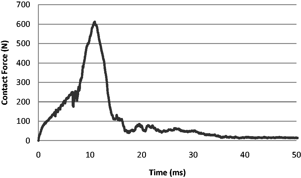
The force–deflection curves obtained by impact tests are displayed in Figures 4 to 6. The trend lines are very different from each other for the three types of knitted fabric-reinforced pipes. As it is shown, UMK pipe exhibits maximum damage resistance, whereas minimum strength is observed in TK pipe. Note that same knitted fabric construction was used as reinforcement for the three pipe types. Linear density and fiber weight fraction are highest in UMC pipes and lowest in TK pipes. From this point of view, it is obvious that UMC knitted fabric-reinforced pipes produced in this study are more sensitive to impact than UMK knitted ones. Although fiber types are the same, UMK shows better performance than TK. The reason of this situation can be explained with the higher linear density and fiber weight fraction of UMK.
Impact force versus time curve of UMC pipe. Impact force versus time curve of UMK pipe. Impact force versus time curve of TK pipe.
When the filaments are twisted the tensile strength of the yarn increases, this is a well-known fact. However, this fact may change when this yarn is used in composite reinforcement, since it is more difficult for resin to penetrate into yarn because of twist [25]. Also untwisted filament takes up more space in the fabric than twisted yarn, and thus, there is less space for impactor to penetrate from gaps located between loops.
The 5 J impact caused damage on all samples. Figure 7 shows photographs of impacted areas. The damaged regions of UMK pipes are smaller than those of the other two pipes. A small local indentation is noticed at the contact point in UMK pipes, whereas perforation occurred in TK pipes and a small irregular crack is observed in UMC pipes. The interlacing of yarns in knitted tubular fabric through the thickness direction increased the splitting toughness and eliminated the delami-nation problem as mentioned by Harte and Fleck [26]. The damage localized at the impact point for three pipes indicates that there is no damage progression. During the impact tests, any circumferential cracks on the lateral sides of the pipes were not observed. Average values of the total damage length were 2 mm, 4 mm, 20 mm transverse and 10 mm, 1 mm, 20 mm longitudinal of UMC, UMK, and TK pipes, respectively.
Damaged zones after low velocity impact test: (a) UMC pipe, (b) UMK pipe, and (c) TK pipe.
Force–displacement responses obtained from axial compression tests are presented in Figures 8 to 10 for both undamaged and damaged pipes. The loading path is quite linear until a first peak is reached corresponding to damage initiation.
Force–displacement curves of the tested UMC pipes. UMC: untwisted multifilament carbon. Force–displacement curves of the tested UMK pipes. UMK: untwisted multifilament Kevlar. Force–displacement curves of the tested TK pipes. TK: twisted Kevlar.


The compressive strengths (

As it can be seen from equation (1), the value of the compressive strength does not depend on the thickness of the composite pipe. The specimens can therefore be compared by considering their fiber weight fractions.
Since the impact strength of UMK pipe is higher than UMC and TK, it was thought that impacted UMK pipe would have higher compression strength. But as can be seen from Figure 11, both nonimpacted and impacted UMC pipes have the highest compression strength.
Compressive strengths of nonimpacted and impacted UMC, UMK, TK pipes. UMC: untwisted multifilament carbon; UMK: untwisted multifilament Kevlar; TK: twisted Kevlar.
Representative photographs at various stages of the axial compression were taken during the testing of the pipes (Figure 12(a) and (b)). These photographs are displayed to give the reader a better understanding of damage caused in knitted fabric-reinforced composite pipes.
(a) UMC pipe before axial loading and (b) UMC pipe after axial loading.
The most dominant failure mechanisms of composite pipes and sections under compressive loading are microbuckling and microcracking [6,27]. Also, in the current study, the failure tooks place as buckling in both nonimpacted and impacted UMC, UMK, and TK pipes. The reason can be explained as during the impact, the nose of the impactor tends to penetrate through the knitted fabric layers creating through thickness material discontinue. Upon compression after impact loading, the portion of the broken loops carrying the compression load acts as unsupported fiber columns and is more prone to buckling [13]. Although Khondker et al. [13] add that this buckling causes a damage initiation for composite plates at the impacted region which propagates in a transverse direction, in composite pipes tested in the current study, such a case was not observed. Even holes occured in the impaction of TK pipes, there was no damage propogation during the compression test.
Conclusion
In the current study, an attempt has been made to develop composite pipes from tubular knitted fabrics by benefiting their near net shape manufacturing capability. Three types of composite pipes (UMC, UMK, and TK) were produced and were subjected to axial compression before and after 5 J impact test. The results of one-way analysis of variance, conducted on the impact test data, showed that impact and compression responses of knitted fabric-reinforced composite pipes depend on fiber type and fineness if the constructions of knitted fabric used for all pipes are the same.
The future research of the author will be to develop composite pipes with different tubular structures, architecture, and layer quantity without changing the fiber type.
Footnotes
Acknowledgements
The author thanks Prof. Dr. Ramazan Karakuzu and Assoc. Prof. Dr. Bulent Murat Icten for their valuable guidance and for allowing to use laboratory facilities for this study. The author also thanks Akar Dogan and Volkan Arikan for their contribution during the experimental activity. Special thanks are also due to Izoreel Company for the support in the specimens manufacturing.
Declaration of Conflicting Interests
The author(s) declared no potential conflicts of interest with respect to the research, authorship, and/or publication of this article.
Funding
The author(s) disclosed receipt of the following financial support for the research, authorship, and/or publication of this article: This work was supported by Ege University under contract number 2013-EAMYO-003.