
Abstract
This paper describes the measurement of packing density and radial packing density of newly developed three-layered, wool structure yarn for pile carpets. Three different varieties of Indian wool, in terms of fibre diameter, medullation and bending rigidity, were strategically positioned in the (ring spun) yarn cross-section. The measurements of all the researched yarns have shown that radial packing density is neither uniform across the yarn cross-section nor maximum at yarn core. The maximum packing density of these yarns occurs at some different distances from the yarn axis and it sharply decreases from that point towards yarn surface. In general, all the yarns are seen to have slight hollowness near their axis. The possible mechanism of the fibre density distribution in the yarn cross-section is also discussed.
Keywords
Introduction
Structural variation of yarn made from different processes and technologies can to a large extent influence the mechanical and physical properties of yarn. In the case of staple yarn, longitudinal behaviour plays more important role in this respect. But the distribution of fibres in the yarn cross-section can also be equally important in deciding the yarn properties [1–10]. The fibre orientation in yarn cross-section also depends on mixing stages of fibres during spinning process. Conventionally, it is required to estimate the average fibre characteristics to decide the blend proportion. The fibres with lesser variation in characteristics are homogeneously mixed and accordingly the mixed fibres influence the process and yarn properties. But in homogeneous blend, the exploitation of the specific fibre characteristics for special purpose is not possible. However, to fully exploit the individual fibre characteristics, the strategically positioning of fibres in yarn cross-section may achieve specific performance of yarn for a required product. Accordingly, different approaches are proposed to produce the multi-component ring spun yarn structures to achieve the objective [11].
However, very less information is available about multi-layered yarn formation technique. Researchers have tried to produce two layered yarn using modified SIRO spinning method with long staple polyester in core covered by short staple cotton sheath [12–15]. In the present work, an attempt has been made to engineer three-layered yarn for carpet pile. Three different varieties of Indian wool varying in terms of fibre diameter, medullation and bending rigidity are strategically positioned in the yarn cross-section. Thus, it opens the area of interest to understand the fibre orientation in newly developed yarns [11].
The present paper describes the measurement of packing density and radial packing density of newly developed yarns. The possible mechanism of the fibre density distribution in the yarn cross-section is also discussed.
Materials and methods
Fibre characteristics of different wools.

Preparation of yarns
The three Indian breed sheep wool viz. Malpura, Magra and Chokla are used to prepare the control and engineered yarns of 4 Nm linear density and 2.2–2.6 twist/cm. Accordingly, three types of control yarns i.e. WLSR on woollen system and WOSR and WODR yarns on worsted system feeding single and two rovings, respectively, were prepared. The proportion of Malpura, Magra and Chokla wools was kept as 1 : 4 : 5 by weight to maintain the commercially accepted proportion of medullated fibres around 40% for control and engineered yarns. But in engineered yarns the Malpura, Magra and Chokla wools were placed in inner, middle and outer layers, respectively, using modified SIRO spinning system. In step 1, firstly two-layered roving structure was prepared at speed frame by sandwiching the roving of Malpura wool between the two slivers of Magra wool. Secondly two-layered Z-twisted yarn was prepared on ring frame.
Three different approaches described in Part-A [11] are used in step 2 as given below:
Two rovings of Chokla wool were placed on both sides of the two-layered roving of step 1, to produce three-layered Z-twisted DR(LRM) yarn. Two rovings of Chokla wool were placed on both sides of the two-layered Z-twisted yarn of step 1. The two-layered yarn was directly fed to front roller nip of the drafting rollers to produce three-layered Z-twisted DR(LYM)Z yarn. Two rovings of Chokla wool were placed on both sides of the two-layered Z-twisted yarn of step 1. The two-layered yarn was fed to front roller nip of the drafting rollers to produce three-layered S-twisted DR(LYM)S yarn.
Preparation of yarn cross-section cutting
To prevent deformation of fibres while cutting yarn cross-section, the mould formation was carried out at two stages. The first-stage yarn was threaded in micropipette with proper ceiling of thin orifice. Care is taken to avoid any twist loss in the yarn during threading. The resin mix for mould was prepared by mixing Araldite resin component of medium grade CY212 and Araldite resin hardener component CY 212 in proportion of 52% and 48%, respectively. To accelerate the hardening of resin mix during baking, few drops of accelerator are also added. The prepared resin mix was poured into micropipette ensuring the straightening of yarn inside micropipette. All the micropipettes are then placed in vacuum oven at a temperature of 40℃ for 72 hours. The hardened resin mould yarn samples were removed from micropipette by removing the plastic shell of micropipette with the help of the sharp blade.
Whereas, in the second stage the resin moulded yarn sample were further moulded with paraffin-wax in order to give better support to the mould while cutting the cross-section. The yarn cross-sections were cut to thickness of 30 µm using rotary microtome. Total 30 cross-sections were considered for each yarn. The images of the yarn cross-sections are captured in camera fitted with microscope at magnification of ×100 and are shown in Figure 1.
Cross-section of different control and engineered yarn.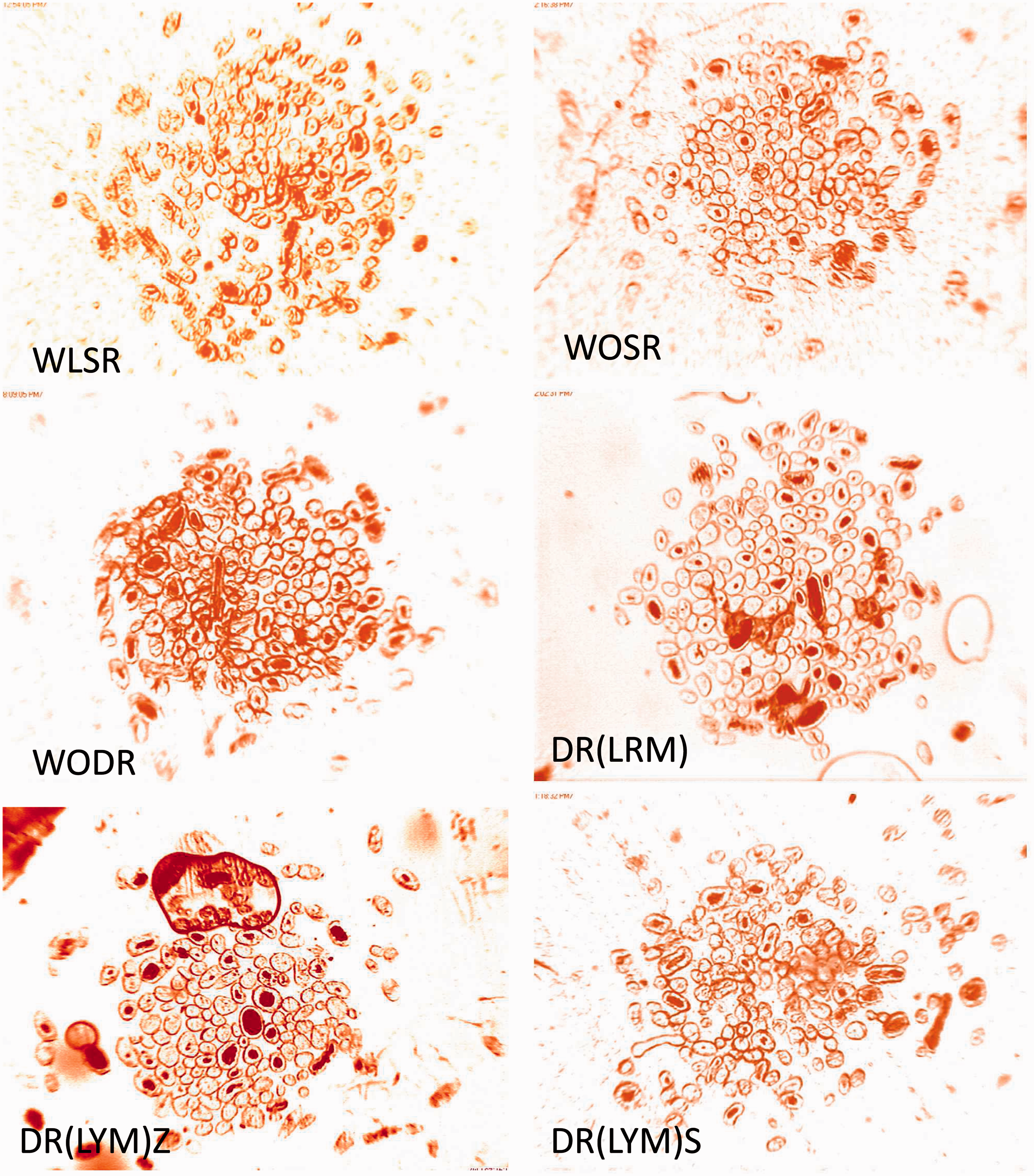
Analysis of yarn cross-section
The study of yarn cross-section is performed by using method of equidistance concentric zones proposed by Necker [16]. In this method, the centre of gravity of yarn cross-section is identified with the help of x-y coordinates of fibres and then yarn cross-section was divided into 20 annular rings of equal width. The area of fibre in the respective concentric circle was measured by using proposed model [16].Whereas, in the present work, the identification of centre of gravity of yarn cross section is analysed using MS office messenger software. The captured yarn image is firstly cropped to the outermost boundary of yarn cross-section, excluding the wild fibres. The centre of cropped image is identified by further cropping the modified image to quarter image in terms of pixel values of image. The centre of the image is then marked as centre of gravity of each cross-section for further analysis. A softcopy of template with 20 equidistance annular rings were developed in MS power point software and grouped. The developed template is superimposed to yarn cross-sections. The template and yarn cross-section was then grouped and picture was saved. The grouped image was analysed by using J-image analysis software. The software converts the saved picture into perfect B&W image and analyse the black component of image in terms of pixel. In yarn cross-section, fibres are observed as black component of the processed image for further analysis.
To find out the area of fibres in pixel of respective concentric zone, the grouped image of yarn cross section was processed to MS power point. The zones are filed with white paint one after the other starting from innermost zone to 20th zone, respectively. Each of the white paint filed image was preserved separately as saved image and analysed for total fibre area in the respective image. The area of fibre in the respective concentric zone is calculated as difference of total area of the concentric zone to the next subsequent zone. The total area of the respective concentric zone was analysed by filling the annular ring with black paint and subtracting the pixel of next annular ring.
Result and discussion
Cross-sections of control and engineered yarns
The photographs of yarn cross-sections of control and engineered yarns are shown in Figure 1. The cross-section of WLSR, WOSR and WODR yarns show that the population of three different wool fibres is well mixed. But Malpura and Magra wool fibres are acquiring in general the outer periphery of the yarn cross-section. This is due to preferential migrational behaviour of stiffer fibres towards outer surface of the yarn. But engineered DR(LRM) yarn has more clustered distribution of fibres, though few stiffer Malpura fibres occupies outer layer of the yarn. Whereas, DR(LYM)Z yarn produces better layer type of yarn structure due to further compacting of core component. The cross-section of DR(LYM)S yarn appeared somewhat similar to that of DR(LRM) yarn, but stiffer fibres are concentrated in few sections of yarn cross-section.
Packing density of yarns
Yarn diameter and packing density of different yarns.

Statistical significance test results.
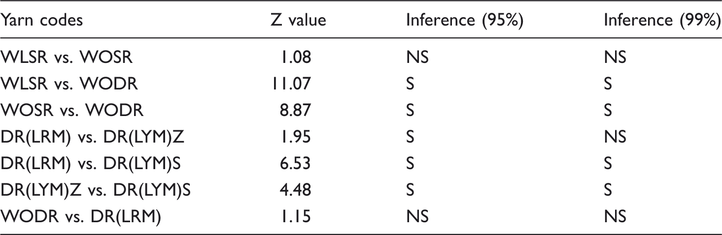
Three-layered engineered yarns are prepared using modified SIRO method and details are given in Part-A of this paper [11]. The changes in packing density of engineered yarns are contributed by two additional factors. Firstly, three different varieties of wool of different fibre characteristics are strategically positioned in the yarn cross-section. Secondly, different approaches are being used to position the fibres in three layers of the yarn. DR(LYM)S yarn shows significantly lowest yarn packing density at 1% level of significance followed by DR(LYM)Z and DR(LRM) yarns. The DR(LYM)Z yarn is produced by placing two rovings of Chokla wool on both sides of two-layered Z-twisted yarn. The two-layered yarn was fed to front roller nip of the drafting rollers to produce three-layered Z-twisted resultant yarn. This makes two-layered core of the yarn further twisted in Z-direction and, therefore, increases packing density of yarn. But DR(LYM)S yarn is produced by feeding two rovings of Chokla wool on both sides of two-layered Z-twisted yarn. The two-layered yarn was fed to front roller nip of the drafting rollers to produce three-layered S-twisted resulted yarn. This will untwist the core part of yarn which increases yarn diameter and results in reduction of yarn packing density. Further, it is evident from our results that DR(LRM) yarn shows highest packing density amongst the engineered yarns. The DR(LRM) yarn is produced by placing two rovings of Chokla wool on both sides of the two-layered roving. All the three strands are drafted together to spun the yarn. Accordingly, Chokla wool occupies the outermost layer, Magra middle layer and Malpura the inner layer of the yarn. The high-tensioned fibres at edges of spinning triangle tend to migrate toward least pressure zone i.e. yarn axis and produces relatively more compact yarn. This justifies the reason of highest packing density of DR(LRM) yarn. The increase is significant compared to DR(LYM)Z yarn at 5% level. It is further noticed that packing density of the DR(LRM) yarn is found to be lower than the control WODR yarn, but the reduction is not significant at 5% level. This is attributed to early binding point in spinning triangle due to presence of two-layered roving in the middle with 5-mm effective spacing between the stands.
Radial packing density of control and engineered yarns
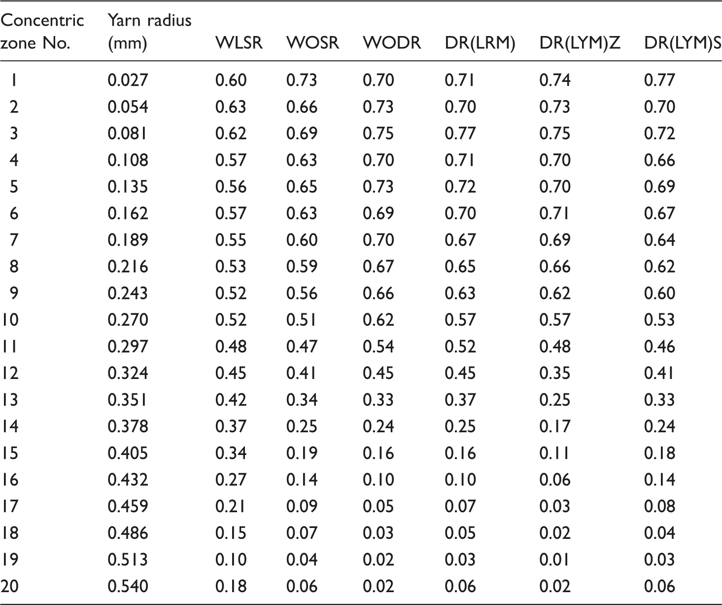
The results of packing density in different concentric zones of control and engineered yarns are given in Table 4. The fibre packing density of the respective zones are calculated as the ratio of the area of fibres in the zone to the total area of the respective zone. The hair fibres outside the last concentric zone are considered in the outermost zone i.e. 20th zone. Accordingly the radial packing density curves have been drawn and are shown in Figure 2. Radial packing density of yarn provides good understanding about the mechanics of building of yarn structure. The results show that curves of radial packing density of all the researched yarns have good resemblance. It is depicted that the radial packing density is neither uniform across the yarn cross-section nor maximum at the yarn axis. This confirms the law of non-linear compactness of fibres in the yarn body. It is observed for all the yarns that maximum packing density occurs at approximately at one-sixth of yarn radius from the yarn axis and it sharply decreases from that point towards yarn surface. In general, all the yarns are seen to have slight hollowness near their axis. The above observation follows hypothesis of ribbon-twist as proposed by different researchers [7,8,17,18]. The fibres are converted from very small ribbon to roughly circular shape at the convergence point of the spinning triangle. The selvedge fibres of the spinning triangle are carrying more strain due to excessive yarn tension, but the fibres in the middle are subject to buckling due to lesser tension. In one situation, the fibre stress is relieved by shortening the fibre path length in yarn and in the other situation by lengthening it. Finally fibres are transformed from purely helical structure to develop an interlocking structure. Due to twist insertion, fibres get longitudinally strained and compete among each other to reach the position of minimum strain near the yarn axis. The movement of the fibres will be highly governed by physical states of fibre competing. Therefore, due to such hindrance of fibre movement in the spinning triangle, yarns are seen to have slight hollowness near their axis.
Radial packing density of control and engineered yarns. Packing density in different concentric zone of yarn cross-sections.
It is observed from our results that maximum packing density of these yarns occurs at some different distances from the yarn axis and it sharply decreases from that point towards yarn surface. Similar trends were also observed by other researchers [7,8,17,18,19]. Soni [20] and Kumar et al. [21] observed maximum helix twist at some distance from the yarn axis. Kumar et al [21] further noticed the occurrence of maximum helix twist in the core zone followed by intermediate zone and surface zone of the yarn. Therefore, it can be concluded that radial distribution of fibre in the yarn and radial distribution of twist in the yarn follow the similar pattern. The above trend was explained by Langenhove et al. [22] while considering that fibres in the yarn core hold higher tension and stress in comparison to intermediate and surface zones. Fibres with more tension require less torque to impart the twist in comparison to fibres with low tension. Thus, core fibres will always have more twist in comparison to intermediate and surface zones. Therefore, the radial twist distribution inside the yarn body becomes the governing factor to decide the pattern of the radial packing density of the yarn and these observations can further be supported by the finding of Kumar et al. [21].
The experimental result of the WLSR yarn is shown Figure 3. The maximum packing density is observed at a distance of one-tenth of yarn radius. But WLSR yarn gives lowest packing density near yarn axis and highest towards surface amongst all researched yarns. The observed trend can be explained on the basis of consolidation mechanism of fibres used in woollen spinning system, which is responsible for open structure of WLSR yarn. The comparative results of WLSR and WOSR yarns are shown in Figure 4. It is evident that WOSR yarn shows higher packing density up to 9/20th of yarn radius and it decreases from that point towards yarn surface in comparison to the WLSR yarn. The results confirm more compactness of WOSR and WLSR yarns towards yarn core and yarn surface, respectively. In the case of WOSR yarn the drafted fibre ribbon converges into spinning triangle. The outermost fibres of spinning triangle are under greater strain and core is subjected to compression. The core fibres take the axial force and the surface fibres take the force radially. The development of the radial force tries to compress the surface fibres towards the yarn core. Finally, fibres get aligned along yarn axis which leads to increase compactness of the fibres towards yarn core. But relaxation of stress on surface fibres opens the surface structure due to fibre slippage and therefore reduces the surface packing density of the yarn. In the case of WLSR yarn, the web is condensed by rubbing action to produce roving. Finally, yarn is produced by providing small amount of draft and twist on ring frame. Therefore, due to criss-crossing, fibres will not follow helical configuration during yarn twisting and results in open yarn structure. But it is expected during roving preparation; the influence of rubbing action will be more effective towards roving surface and therefore, increases the compactness of surface fibres. Therefore, the amount of twist and draft used at ring frame is not bringing much change in fibre packing mechanism of WLSR yarn.
Radial packing density WLSR yarn. Radial packing density of WLSR and WOSR yarns.

Further, it is noticed from Figure 5 that in between WOSR and WODR yarns, WODR shows more compactness towards yarn core and lesser compactness towards yarn surface than WOSR yarn. The WODR yarn follows the SIRO spinning method by feeding of two rovings with 10-mm roving spacing at ring frame. The method enables a special yarn structure by exploiting the technological process as already explained above. The described consolidation mechanism is responsible to increase yarn compactness. The researchers [14,15,23] have also confirmed higher packing density of double-roving feed yarn than single-roving feed yarn.
Radial packing density of WOSR and WODR yarns.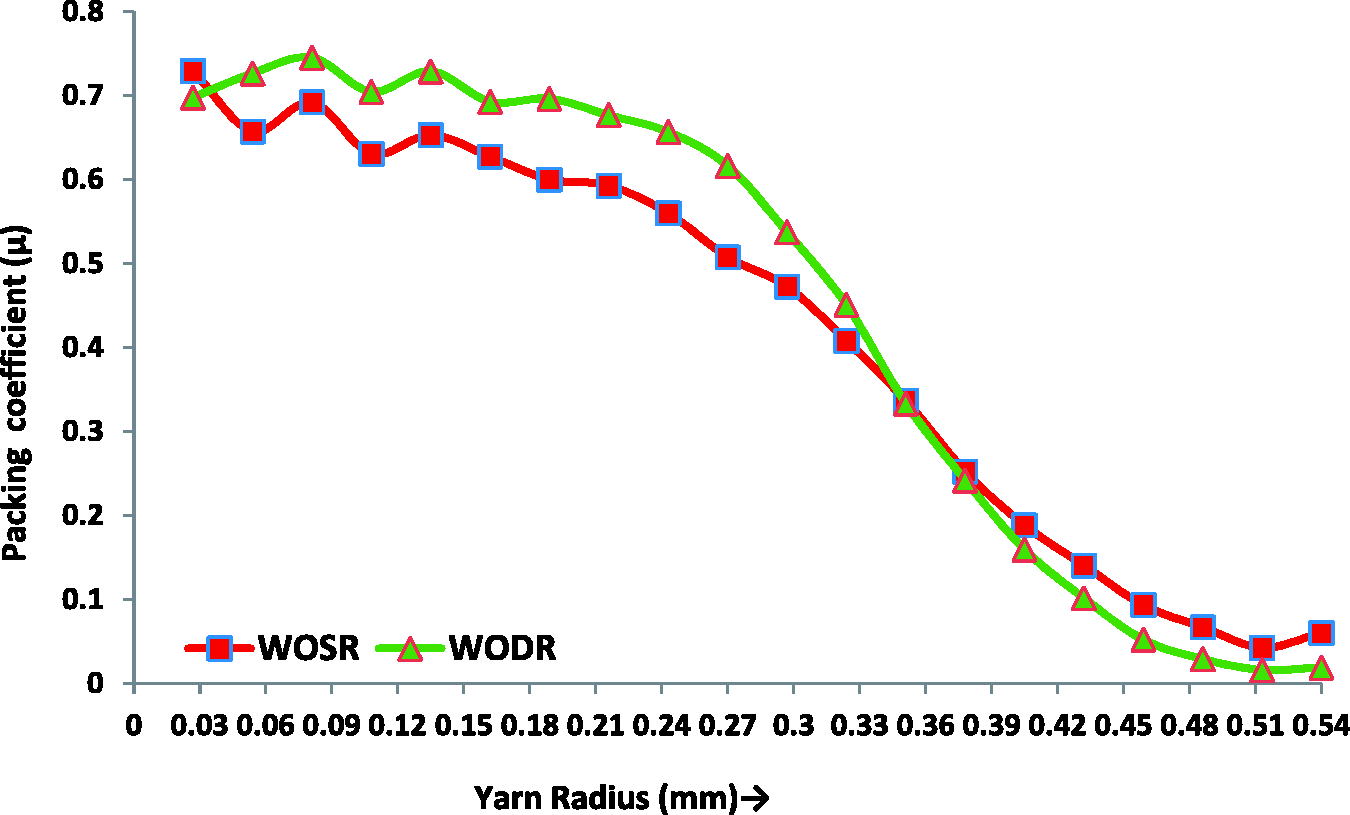
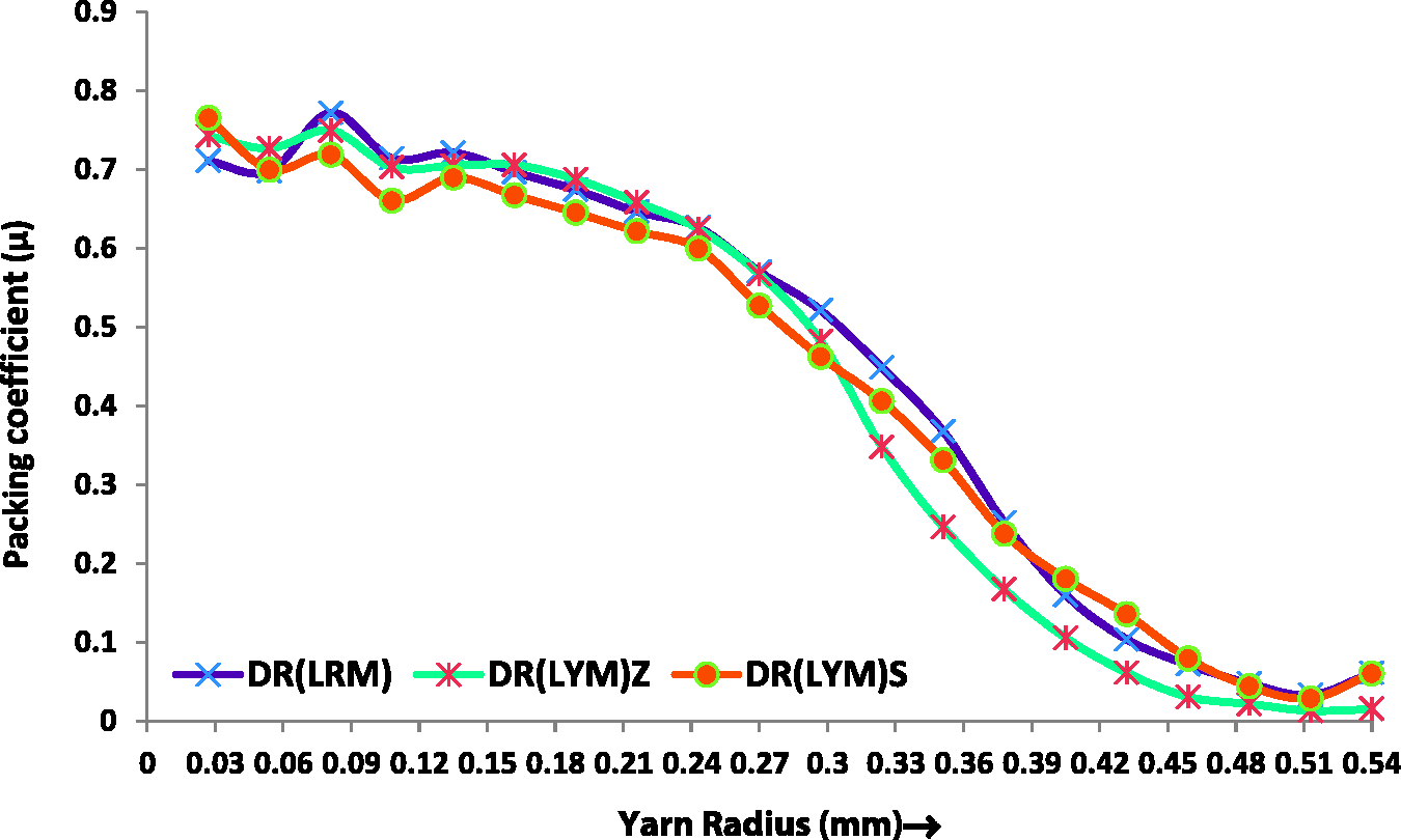
It is required to understand that changes in packing density of engineered yarns are contributed by two additional factors i.e. strategic positioning of fibres in yarn cross-section and multi-component ring spun yarn structures in comparison to control yarns. The explanation given above justifies the increase in compactness of core portion of DR(LYM)Z yarn and decrease in compactness of core portion of DR(LYM)S yarn. This change will influence the radial packing density of resultant yarns and is clearly evident from Table 3 and Figure 6. The results indicate that DR(LYM)S shows lower packing density up to 0.297 mm radial position from yarn axis but higher packing density towards yarn surface compared to DR(LYM)Z yarn. The increase of packing density of DR(LYM)S yarn towards yarn surface is due to untwisting torque of core yarn which helps the surface layer of the resultant yarn to get more compacted. But in case of DR(LRM) yarn, the presence of two-layered roving in the middle will give lesser packing density near yarn axis and higher packing density in the intermediate zone in comparison to other two engineered yarns. The results of Figure 7 confirm that DR(LRM) yarn enjoys the fullest advantages of SIRO spinning system.
Radial packing density of DR(LYM)Z and DR(LYM)S yarns. Radial packing density of DR(LRM), DR(LYM)Z and DR(LYM)S yarns.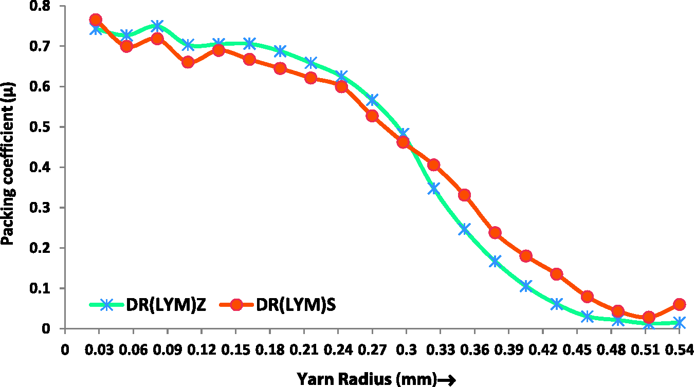
Conclusions
It can be concluded from our result that amongst three control yarns, the WO-DR yarn made on worsted spinning system with double roving feed gives highest yarn packing density followed by single roving WOSR worsted yarn and single roving WLSR woollen yarns. But amongst three engineered yarns, DR(LYM)S gives minimum yarn packing density followed by DR(LYM)Z and DR(LRM) yarns. The packing density of the DR(LRM) yarn is found to be lower than the control WODR yarn. The radial packing density of all considered yarns is found to be neither uniform across the yarn cross-section nor maximum at yarn axis. For all the researched yarns, the maximum packing density occurs at some different distances from the yarn axis and it sharply decreases from that point towards yarn surface. It is observed from our results that in general the yarns are seen to have slight hollowness near their yarn axis.
Therefore, it can be concluded that present work has proposed different approaches to produce multi-component ring spun yarn structures and created possibilities to manipulate the radial packing density of yarns to exploit its advantages in different end products.
Footnotes
Funding
This research received no specific grant from any funding agency in the public, commercial, or not-for-profit sectors.