
Abstract
A novel braiding–weaving system (BWS) is developed offering broad design and manufacturing possibilities based on hybridisation of weaving and braiding. In order to understand and optimize this machine and to be able to explore all the possibilities regarding complex 3-dimensional (3D) structures design, a new modelling strategy has been developed to generate geometrical skeleton of those structures. This strategy is based on the collision detection and kinematic aspects of the machine itself. Hypothesis given by kinematics allows to simply change the structure type (i.e. braiding or weaving) by changing the yarns paths. Those hypotheses are introduced in the article followed by the model that has been used and the collision detection method. Modelled 3D textile preforms are compared with manufactured samples in order to evaluate the accuracy of the modelling and simulation approaches.
Introduction
For composite applications, a good knowledge of the textile manufacturing process is a major issue for material design. In the field of textile preforms, and more particularly 3D textile preforms, textile manufacturing [1–8] represents a complex step from 1-dimensional (1D; tows) to 3D dry preform. Three-dimensional textile processes introduce new tows interlacing, new available orientations and reachable volume fractions. So, all those transformations result from a process defined by machinery tools and other fibres interferences and contacts.
Textile reinforcements for composite materials need modelling in order to bring the prediction of formability and mechanical properties. Textile reinforcement is a multi-scale material [9–14] that is described by Lomov et al. as a hierarchical sequence: ‘fibre→yarn→textile→preform’. That multi-scale approach makes the modelling more complex, because it is necessary to study first the microscale (fibre) then the mesoscale (elementary cell) and finally the macroscale (preform) [9].
Among available models, WiseTex [15] is based on the yarn properties and gives a description of the relaxed structure a priori according to a geometrical description of the interlacing. The use of yarn properties coupled with a static relaxation gives better description of textile architecture. TexGen [16] is a modeller based on the discrete description of the yarn trajectory and its section, it has been developed by Sherburn et al. [17]. Modellers are suitable for textile characterisation when the number of interlacing is weak. These modellers are not programming to generate structures from machinery description.
3DbraidTex [18] is a part of the WiseTex package and allows to give a 3D braid geometry from manufacturing sequences. It makes the link between manufacturing and geometrical description of the preform. However, contacts between yarns are not taken into account and leads to yarns interpenetration within a model.
Some models generate textile architectures directly from the process description step by step in order to obtain a realistic structure based on contact and sliding between yarns. Wang and Sun have developed digital rod element (DRE) approach [19] which consists of rod joined by frictionless pin. By describing the yarn trajectory, it is possible to construct textile architecture. This model has been improved and extended [20,21] in order to reduce time consumption. Based on this model, Miao et al. have proven that it is not necessary to consider the yarn as a multi-chain of DRE [22] in order to reduce computation time. Other approaches are proposed by Pickett et al. [23,24] based on explicit resolution method or Durville [25–27] based on an implicit method. Those methods give a good description of the textile architecture but need considerable resolution time [28] and must be dedicated at generating models for precise modelling.
In our context, the objective is to describe the textile interlacing to help the designer and verify the good setting of a new machinery [29,30]. This technology allows a wide range of 3D interlacing and can be totally reproduced on our machine. A model must be constructed from the kinematic description of the manufacturing steps that have been explained previously [31]. Such approaches exist but the given descriptions are too precise and are not adapted to our needs (too much time consuming).
The paper briefly presents the technology used for manufacturing and the modelling context. In order to reduce the computational time, a new algorithm has been developed insuring good enough precision. This modelling tool gives a fast and comprehensive geometrical description of the meso textile architecture. This tool does not aim at a fine description of the geometry, but brings enough information to evaluate whether the virtually created structure corresponds to the one expected by a designer.
Machinery description
A braiding–weaving system technology (called BWS) has been developed in order to manufacture 3D textile preforms. The originality of BWS consist in the hybridisation of two existing textile technologies: braiding and weaving. It means that weft threads are inserted following predefine angles into the braided structure.
Each yarn is independent and used to create complex shaped structure, with tailored interlacing and non-regular architecture. The principle is based on our previous patent [30] and is described in Figure 1a. The two sets of yarns used are warp (mainly in the production direction) and weft (orthogonal to this direction). Each warp yarn is tension controlled and guided by the specific case (Figure 1a). All the guides together in row and column form the production matrix. It allows vertical and horizontal displacement of guides. Those displacements are totally automated and offer wide range of interlacing, for example dual orthogonal shedding for 3D weaving [1] or four-step braiding [32]. After this displacement, the warp set is rearranged and can be stabilized or improved by the insertion of weft yarn in transverse direction. This insertion is also tailored with the control of the insertion space and the insertion angle with a complete rotation device.
(a) BWS principle description and (b) laboratory loom.
The matrix mobility (Figure 2) is a combination between 3D braiding and 3D weaving which brings new interlacing possibilities for preforms. Each case can move within the matrix to reach any position. Case displacement and insertion will interlace tows together by interference. To design 3D structure, it is important to predict interferences and its result on global textile architecture. For this reason, a geometrical description of yarn interlacings linked with the manufacturing parameters is necessary in order to predict the structure of the final design.
Description of matrix mobility.
Model and collision detection algorithm
This model is based on a basic geometrical description of the yarns forming the structure, and aims a mesoscopic modelling of the yarns as follows:
yarns are considered by their centreline and section; section is circular and constant along the centreline; centreline is defined by nodes joined by segments; mechanical material properties are not taken into account.
First (Figure 3, yarn initial state), yarns are made of two nodes. One node is fixed and the other is free to move following the manufacturing process. While the free node is moved, nodes are added (Figure 3, textile preform) to the yarn to describe trajectories modifications during the process of braiding and weaving. Added nodes have been formed from contact between two yarns and they are considered fixed. In this approach, a model is restricted to the minimal amount of data at the beginning. Then, the needed data are added step by step when necessary. A main difference with other models is the modification of the model complexity in the time in order to keep the model simple, enabling fast computation.
Modelling description from initial configuration to modelled textile preform.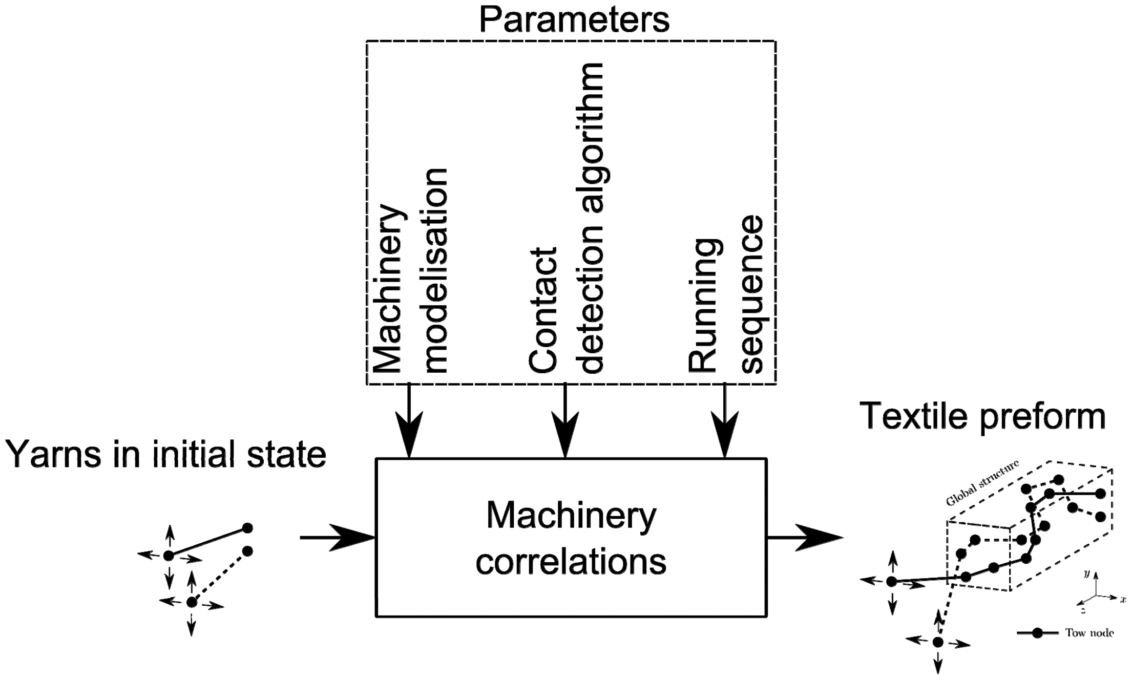
The interference detection generates modification of the structure by nodes addition. Several approaches can be used to implement the interference aspect. Comparing distances between nodes for each time laps describing the displacement may lead to a high number of operations to solve and, therefore, to an increase of the computational time. In order to compute fewer operations for the interference detection, the complete yarn motion is taken into account.
Machinery sub-model
The BWS process described in ‘Machinery description’ section is considered as sub-model of the machinery for modelling. To run out this modelling, a virtual description is made and presented in Figure 4. Parameters are as follow:
Dyarn = yarn diameter (mm); Gh and Gl = guide width and height (mm); Nc and Nr = number of column and row; P = step forward for take-up (mm); Dmat = distance from matrix to preform (mm); Cmat = the ratio between gap at preform a and the matrix b (mm). Parameters and virtual description of the manufacturing process.

Interference detection sub-model
This approach is based on computational graphic science and collision detection in virtual environment [33,34]. When the free node is moved from position A1 to position A2, the sweeping of segment describe a triangle surface (Figure 5). For a given motion, all the encountered yarns can be detected using a triangle/segment algorithm detection [35–37].
Yarn 1 displacement from DA1 to A2B and collision detection with yarn 2 (CD).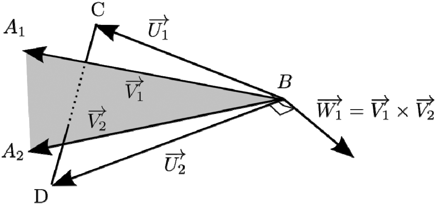
If we consider a yarn 1 described by its nodes A and B, A is the mobile point and B is fixed. Another yarn 2, described by C and D is there for a collision test. By determining barycentric coordinates of C in the tetrahedron DA1A2B [36] it is possible to detect interference with tests on those coordinates and to return the intersection point as presented in Figure 5. This method has been implemented in textile modelling algorithm in Figure 6, which describes the motion of yarns according to the BWS technology presented before.
Detection algorithm chart flow for a line instruction.
Modelling tool
Associated to our system, software is developed to command the machinery kinematics and also to model interlacing of the yarns before or during real production. This tool is based on our algorithm and a dedicated graphical user interface (GUI). GUI is available (Figure 7) for modelling description and allows:
to fill guides with yarn in virtual matrix; displace matrix row and column (single or multiple); insert yarn with orientation control (under development); display modelling; return instructions for laboratory loom. GUI for modelling control and display.

The modelling result can also be interfaced with other modelling software such as TexGen [16,17] in order to visualize and exploit data for post-treatment if needed. Presented algorithm makes modelling of the BWS process possible. The following section will present the validation of the model on calibration cases and then application of the modelling tool for 3D shaped and interlaced structures.
Model validation
After first tests concerning collision detection between two elements in order to validate the triangle/segment detection approach, more complex scenarios allow textile structure modelling based on the description of the process. Structures for evaluation and calibration of the model are interference between two yarns (twisting), braiding (8 yarns) and weaving yarns (begin at 10 yarns and add yarn for each weft insertion). Based on those cases, a first understanding of the algorithm possibilities is done.
Two yarns twisted together is the first basic case that has been investigated. Yarns were fixed on one extremity and twisted from the other one. Twisting trajectory is defined as follows: four linear steps for each yarn in the same plan (Figure 8) and out of plan motion for the take up.
Trajectory for yarn twisting.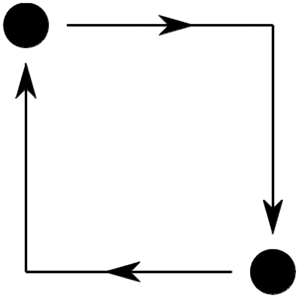
For each yarn, initial configuration is made of two nodes, then the twisting trajectory and finally the developed algorithm modify the yarn path by adding nodes as shown in Figure 9. The modelling is based on process description, and every parameter has a coupled interaction on modelling output.
Yarn structure before at initial and twisted configurations.
The model is also able to handle more complex structures by increasing a number of tarns and manufacturing steps. Next case is a four-step [32] braided structure made of eight yarns. Modelling (Figure 10) generates an interlaced structure with all the yarns as expected.
Four-step braid with eight yarns: (a) nodes and trajectories, (b) yarn volume and (c) section view with interpenetration.
In order to simulate the weaving process and particularly weft insertion, yarns can be added during the simulation process. Figure 11 shows a plain weave modelled by adding weft yarns just before warp yarns motion. The main disadvantage for geometrical modelling, weft inserted yarns remains straight instead of being crimped. However, nodes are added to weft inserted yarns at the contact point with warp yarns, from this nodes, it is possible to apply a static relaxation for further investigations.
Modelling for plain woven structure from different views: (a) side, (b) up and (c) isometric.
Modelling time for 10 cycles.

Results and discussion
Based on modelling algorithm, two 3D textile structures have been modelled: 3D braided structure with ‘L’ shaped cross section and 3D woven structure with ‘U’ shaped cross section. GUI is used to set the modelling in the same way as the manufacturing parameters of those samples manufactured on a laboratory loom. Both virtual and real geometries are then compared to highlight achievements and limitations for modelling approach.
‘L’ braided structure is based on the machinery filling described in Figure 12. From this configuration four-step braiding [32] is used to move the yarns and create the interlacing. Same sequence used on the real machinery is set to the modelling software GUI to drive it. All the yarns are made of two nodes at the beginning and they start to move and interact with others. From this interaction, nodes are added to modify structure as presented.
Initial configuration of the machinery and model for the ‘L’ braided structure.
The complete structure is made in 138.15 s for 10 action cycles and 504 interferences are detected. Figure 13 shows the result exported and sliced into TexGen. Interlacing takes into account all the yarns within the structure; yarn volume is also handled in a satisfactory way and shows low interpenetration. It can still be increased and as the contact direction is known, non circular yarn cross section is possible. The same structure has been produced and results are compared in Table 2. As foretold, no deformation occurs after interference between yarn and leads to gap between virtual and manufactured sample. Either some parameters are close from manufactured sample though.
Modelling results and parameters for ‘L’ braided structure. Comparison of geometry parameters for virtual and manufactured ‘L’ braided structure.

A 3D woven structure is made based on dual directional shedding [1]. The complete modelling takes 376 s for 10 action cycles and 610 interferences are detected. The result is shown in Figure 14 after TexGen [16] exportation and slicing. The interpenetration is still low, but lack of compaction and sliding leads to gaps between yarns within the section. As a result, geometrical parameters presented in Table 3 highlight significant differences between the virtual results and manufactured samples.
Modelling results and parameters for ‘U’ woven structure. Comparison of geometry parameters for virtual and manufactured ‘U’ woven structure.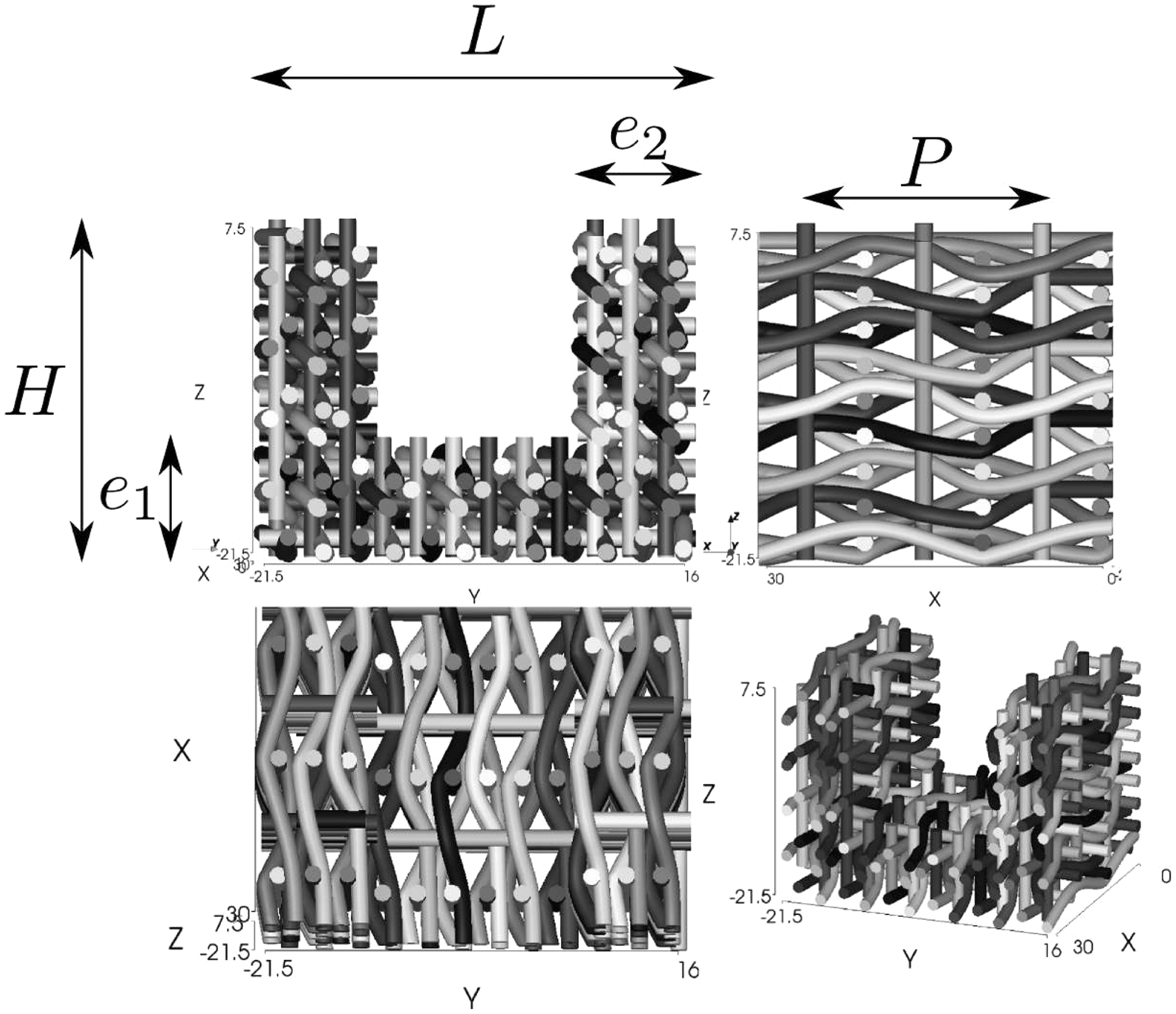

As presented before, crimp is not taken into account for inserted yarn. That increases the gap between simulated structure and real one. On the other hand, contact information is embedded in the skeleton which can be exported into other software or processed with mechanical behaviour such as static relaxation. Figure 15 gives a representation of data embedded within the skeleton: yarns made of nodes and the link between two nodes in contact.
Skeleton overview with yarns made of nodes and link between two nodes in contact.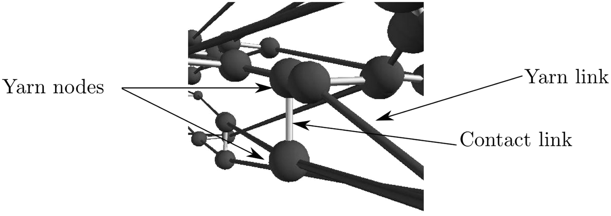
Conclusion
Present article introduces a new algorithm for 3D textile modelling based on geometrical collision detection. Algorithm is based on segment/triangle detection leading to the modification of the yarn paths. Yarn description is basically made of straight lines described by two nodes and a constant section. No mechanical aspects are taken into account. The main objective of the algorithm is to give a comprehensive description of the textile architecture in a short time computing. First, model has been validated on basic cases (twisting, braiding and weaving). Then, it has been applied to complex shaped 3D weaving and braiding structures. A good description of the interlacing is obtained by the skeleton of the virtual preform. This skeleton or pre-mesh can be exported in other software if needed, for finite element modelling for instance.
Model limitations are obvious but it does not aim at a realistic modelling, but a comprehensive pre-mesh and it can be improved in two manners. First one regards the inclusion of nodes displacement by weighting and tension equilibrium. Second one consist an application of mechanical relaxation methods to simulate accurate geometrical model. The main advantage is to obtain the skeleton and evaluate the architecture and then process or simulate it.
Footnotes
Funding
This work was supported with by the Regional Council Nord – Pas de Calais, the Regional Delegation of the French State and the European Regional Development Funding, in the framework of UP-TEX cluster and FUI program.