
Abstract
Drape simulation of textiles is a field of research, which is known in the clothing sector for a long time. The ongoing development of high-performance composites made of textile reinforcements and matrix materials focus the interests on a serial production in many industrial sectors, such as aviation and automotive industries. Challenges occur mainly in the serial production technologies and in supplying concepts for the preform architecture and shape. Research aims on the acceleration of preform manufacturing and the reduction of expensive pretests. Numerical simulation models can help to improve the composite development chain with structure and process simulation. A special challenge in drape modeling is the bending behavior of textiles. This study introduces a novel approach for modeling single textile layers as laminates to gain a correct mechanical behavior, where all deformation mechanisms are uncoupled. The implementation in the finite element software LS-DYNA® is described. An algorithm is introduced which provides the membrane stiffness for each layer of a laminate to fit the measured cantilever bending stiffness of textiles in every bending direction and bending side. The calculated parameters for the laminate formulation result in the requested bending stiffness for the textile layer. The cantilever bending stiffness can be used directly for dimensioning the model.
Introduction
The steadily increasing usage of fiber reinforced composites requires improved production technologies to handle the increasing quality demands and to reduce the development time for novel structural parts. The manufacturing of composites with textile reinforcements typically requires the preforming of the dry textile and the subsequent resin infusion and consolidation. This preforming requires decisions on the applied textiles, on their positioning in the forming tool and, if applicable, on zones for special pre-treatments such as structural fixation with binders or stitches. The development of the preform design, the shape and zones for pretreatment with experimental design is very time-consuming and expensive. Numerical forming simulations assist with decisions in the preform development process. Forming or draping simulation is a tool in the development chain of structural composites made of reinforcing fiber materials.
The accurate prediction of wrinkles is one of the most important challenges in a drape simulation. Complex textile structures induce high deformational rates into the fabric while forming. These strains lead to local or global shearing and bending effects. Wrinkles can be seen as a local buckling problem. Boisse et al. [1] characterized the importance of a correctly described shearing and bending behavior for the propagation of wrinkles and mentioned that the formation of wrinkles reduces the internal strain energy. The increase of the shear stiffness above the critical locking angle was identified as the main reason for wrinkle forming. Boisse et al. [2] also stated that there is no direct relationship between the local shear angle and the forming of wrinkles. The bending stiffness and the interaction of shearing and bending stiffness, respectively, were accounted for the wrinkle size and the number of wrinkles formed. Thus, numerical drape simulations with membrane elements are unsatisfying for the simulation of wrinkling. Hedfi et al. [3] also indicated the necessity of a correct description of the textile bending stiffness in a numerical model for an accurate prediction of wrinkling [3].
This article introduces a finite element model, which reproduces all main deformation mechanisms of textile reinforcements and their nonlinear character. The presented approach configures the textile structure as laminate. Thus, all resulting deformation mechanisms are treated correctly and the membrane and the bending rigidities are decoupled. Furthermore, the material model considers the different bending rigidities of textiles, which depend on the bending direction and the bending side. With this novel approach of a fabric material model considering the bending stiffness of textiles an implementation into commercial finite element analysis (FEA) software is possible.
Modeling approaches
In the clothing industry many techniques are known for predesigning precuts and laying up 2D textiles into 3D shaped forms [4–6]. Kinematic or fish-net algorithms were used. However, those approaches do not account for stresses within the structure and are not able to commit on the microscopic layout of the textiles. The alternative is a mechanical model that represents the non-linear material behavior of textile reinforcements [7–11]. Technical reinforcement textiles exhibit low bending and large tensile rigidities. This differentiates them clearly from traditional construction materials, such as metals. One of the challenges of the continuum mechanics approach is the decoupling of the bending and the membrane rigidities in the constitutive law.
In continuum mechanics approaches in the scope of the FEA the low bending stiffness was often neglected and membrane elements were used [12]. The correct prediction of wrinkling while forming is necessary for a successful fabric drape simulation. The forming of wrinkles leads to a lower level of internal energy compared to a further shearing of the fabric. Thus, the neglecting of the bending rigidities, as most FE textile models do, is inappropriate for the simulation of textile material forming.
Sriram and Wagoner [8] introduced a membrane element, which considered the bending energy. Chen et al. [11] considered this energy through the change in the angle to neighboring elements. Hamila et al. [9] proposed a triangular shell element for textile forming simulation, where internal virtual work was included in dependence of tension, shear and bending moments. The bending moment was obtained from the displacement of neighboring elements. Another solution was introduced in references [13,14] where a beam model was proposed that considered all deformation mechanisms. The bending rigidities were defined through the cross section of the beams. Jannski and Ulbricht [15] also refer to the problem of decoupling the bending and the membrane rigidities of shell elements. They presented a shell element based on the Coserat theory, where all shell rigidities were independent of each other. However, the determination of the material input parameters from mechanical tests is challenging. A simplifying but common assumption based on the bending theory of classical materials was acquainted in references [16–19]. The Young’s modulus was arranged such that the resultant bending stiffness was identical to the one measured with a mechanical cantilever bending test. Such a change of the membrane tension stiffness of technical textiles is mostly uncritical for drape simulations but insufficient for a general material model.
Another possibility of modeling the drape behavior of textile structures is a particle-based assumption [20–22]. Particles were often placed in crossover points of weft and warp yarns. An energy potential defined the interaction of the particles, which contained e.g. tension and bending energies. Particles which move out of the plane determined the amount of the bending energy. Wagoner et al. [23] introduced an element bending group technique that allowed the membrane elements to account for bending.
Gereke et al. [24] gives a literature review dealing with the state-of-the-art in textile forming, characterizing and simulation. Multiple papers are discussed which account for several problems of drape simulation.
The bending behavior of textiles – Characteristics of fixed and unfixed structures
The bending behavior of textiles differs significantly from those of classic materials such as metals. The bending rigidity of textile structures does not directly depend on the Young’s modulus and the cross section. The possible motion between the yarns yields a very small textile bending stiffness, which results from the yarn rigidity and inner frictional effects due to crossing of the yarns. The effects of friction and yarn compression cannot be determined theoretically.
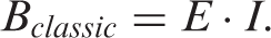
In classic materials the Young’s modulus, E, and the moment of inertia, I, typically define the bending stiffness, B, as
In fibrous structures and for measured bending stiffness this would lead to a Young’s modulus of textile structures, which is much lower than the actual one. This approach can only be used if the membrane stiffness can be neglected [16,25]. It is suitable for analyzing the folding behavior of textiles under gravity loads. However, in technical forming tools with blank holders the nonlinear membrane stiffness has to be taken into account in a realistic model.
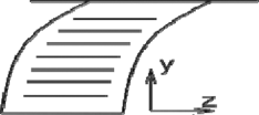
The approach presented in equation (1) is insufficient for a general textile material model since most technical reinforcement textiles exhibit very high tension stiffness and a nearly negligible bending stiffness. Challenges occur in textiles with an asymmetrical layout or an asymmetrical state of pre-stress. As an example, the meso-structure of a biaxial reinforced multilayer knitted fabric is shown in Figure 1. Here the asymmetrical layout and the asymmetrical knit yarn system cause the bending stiffness to depend on the bending side (top and bottom side, see Figure 1) and the bending direction (x- or y-direction).
Model of a biaxial reinforced multilayer knit.
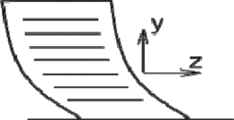
Another challenge for a realistic model is the influence of interventions in the mesoscopic design, such as structural pre-fixation. Girdauskaite [26] described a textile pre-fixation with thermoplastic binders. Cherif et al. [27] melted and consolidated the thermoplastic part of hybrid yarns that were integrated into the textile and, thus, achieved a structural fixation of the fabric. It was shown that fixed textiles are much stiffer in their bending and shearing behavior than unfixed ones. The effect on the tensile stiffness and the structural layout was negligible. Most of the pre-fixations substituted the yarn–yarn friction with a yarn–yarn adhesion. This resulted in a significant increase in the structural bending stiffness. The effect of such a pre-fixation can be seen in Figure 2.
Effect of structural fixation on the bending behavior of a biaxial reinforced knitted fabric.
Material
Layout of biaxial reinforced multilayer knitted fabric.

GF: glass fiber; EC: E glass; HY: hybrid yarn.
Methods
Determination of the bending behavior
The bending behavior was measured with a cantilever bending test according to DIN 53362 [28]. The device is schematically shown in Figure 3 and the determination of the overhang length is illustrated in Figure 4. In this test a strip specimen is pushed over an edge at a constant velocity. This edge is a reference for the overhang length, l
o
. Owing to gravity the strip bends depending on the current overhang length. If the sample reaches an imaginary line which is in 41.5° angle from the tip of the sample to the reference edge, the overhang length is determined. The deflection results from the overhang length.
Experimental setup of cantilever bending test (according to reference [28]). Deflection of specimen strip at l = l
o
.

With

Material model based on the laminate theory
The laminate theory consists of some basic computation rules that allow the calculation of the mechanical properties of layered material. In the current approach the laminate theory is used to describe the characteristic anisotropic behavior of one single textile layer (one warp and one weft layer). The resulting macromechanical properties are known from mechanical standard tests, such as the strip tension test according to DIN EN ISO 13934-1 [30], the picture frame shear test as described e.g. in reference [31] and the cantilever bending test according to DIN 53362 [28]. In the presented model a laminate replaces one single textile layer containing one weft and one warp yarn layer. A schematic representation of the assembly of a symmetric laminate is shown in Figure 5.
Example of laminate design.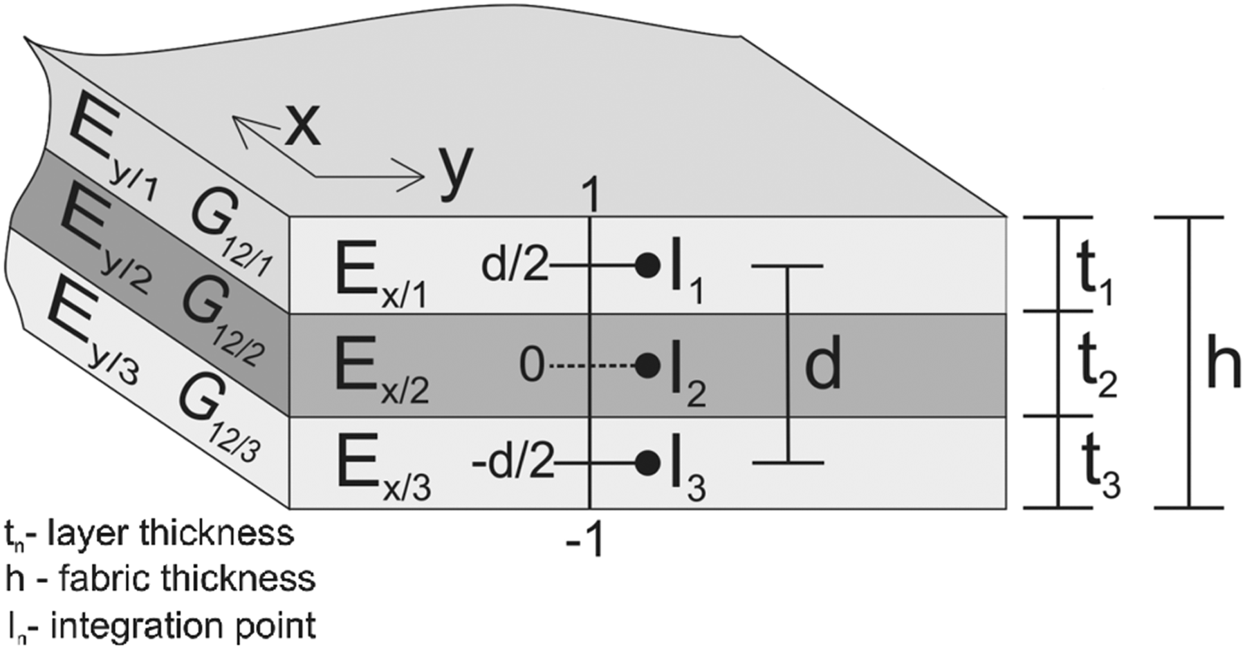
The layered formulation given below assists in correctly generating all resulting deformation mechanisms.
The following basic equations are used for the computations. The resulting Young’s modulus of the laminate is given by the rule of mixture as

The layer thickness of the nth layer is denoted as tn, the thickness of the laminate is given by h, and the volume fraction of the nth layer is symbolized by ϕn. Similar to equation (3) the resulting shear modulus, Gxy, of the laminate is determined as

As illustrated in Figure 6 bending causes tension on one side of a plate and compression on the opposite side. Those bending sides cannot be considered within equation (1). For classic materials and small deflections the stress–strain behavior is the same for tension and compression loads. However, this is not the case for fibrous materials. Thus, the current material formulation considers the bending side with the integral over the thickness of the plate (equation (5)). The laminate bending stiffness is computed as follows
Bending behavior of laminates.

To allow for different bending rigidities on both bending sides (top and bottom side) different stress–strain behaviors for several layers have to be defined. Otherwise, the laminate bending stiffness given in equation (5) would be independent of the bending side.
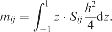
Commercial FEA codes offer some possibilities to handle layered materials. Shell elements, which are based on a solid material law, are pre-integrated in the thickness direction. Thus, the volume integral of the stiffness matrix, Cijkl, becomes an area integral [32]

With this integration the static variables of the membrane forces, transverse force and moments are calculated. The solution for the moments, mij, according to equation (6) can be defined as
The pre-integration happens numerically at certain integration points, which are presented together with the integration limits in Figure 5.
Material parameters and calculation
According to reference [33] the primary deformation mechanisms of textiles are stretching, shearing and bending. The engineering constants, which correspond to them, are the Young’s modulus E, the shear modulus G and the bending stiffness B. The calculated layer parameters of the laminate model for influencing the bending behavior must not affect any of the other deformation mechanisms. Thus, the layer material parameters have to be defined in a way that they result in the textile macroscopic behavior. For reasons mentioned earlier, this is not possible with only one layer. A minimum of three layers has to be assumed in the laminate formulation. This leads to n = 3 and the consideration of the bending side independent stiffness for the x-direction leads to: 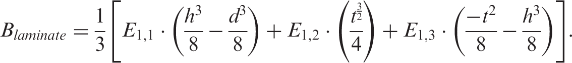
The amount of unknown variables requires some assumptions. Choosing constitute layer thicknesses leads to a closed-form solution. These assumptions allow for a free choice of the bending stiffness with simultaneously constant membrane stiffness. Thus, it is possible to justify the complex bending behavior of unfixed and fixed textiles. An orthotropic formulation allows the handling of different bending rigidities in the different bending directions (0° and 90° orientation). A unique Young’s modulus in tension and compression for the outer laminate layers allows for the correct bending side dependent bending behavior (top and bottom side). The Young’s modulus of the inner layer adjusts the resulting in-plane stiffness.
Results and discussion
Cantilever bending test
Overhang length of unfixed and fixed samples according to DIN 53362 [28].


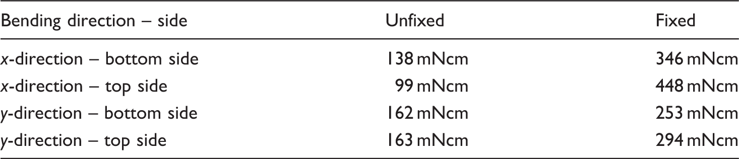
Bending stiffness of unfixed and fixed samples according to DIN 53362 [28].
Model application and examples
Bending stiffness and Young’s modulus for each layer in laminate formulation.

The calculated layer parameters were checked for their correctness with a cantilever beam simulation. In the FEA model that was implemented in LS-DYNA® a strip sample with the length l
o
was clamped at one side and loaded with a gravitational load. Figure 7 plots the results of the cantilever simulations. The deflections of the shell elements with a classic formulation (equation (1)) and the modified shell formulation are referenced.
Solution of the cantilever simulations.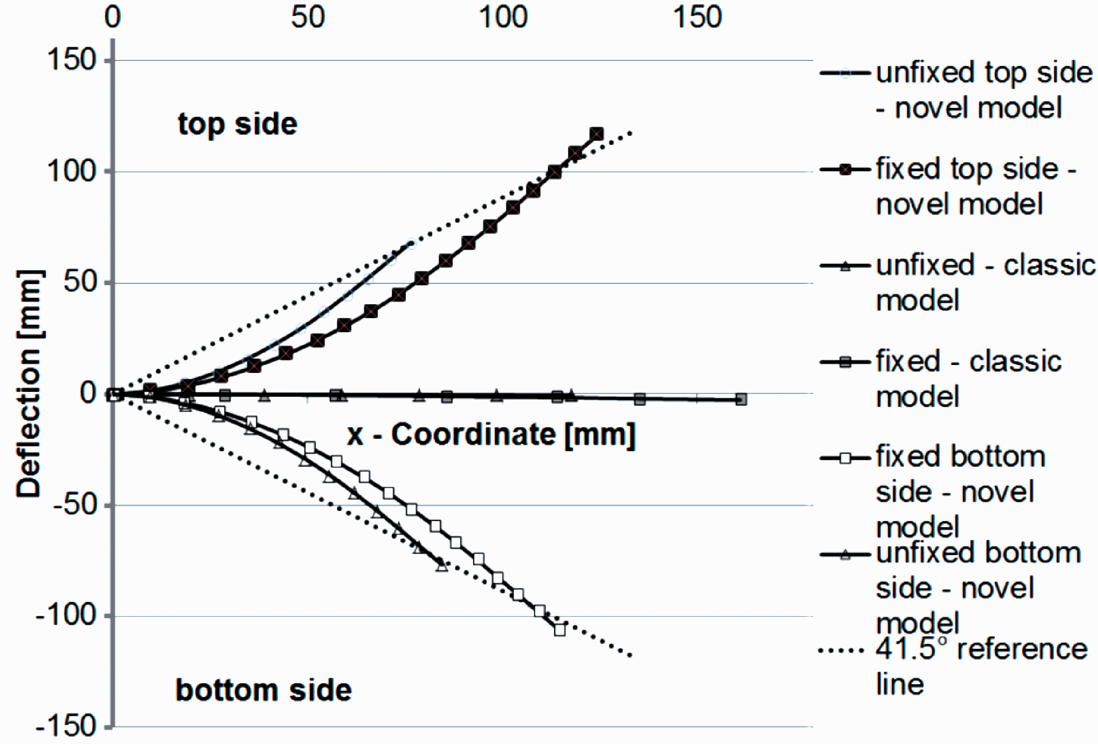
As can be seen in Figure 7 the application of a classic shell element formulation results in a large deflection error. The deflections of the modified laminates coincide with the real deflections measured by means of the cantilever bending test. Furthermore, with the developed approach it is possible to handle the deflections as a function of the bending side.
A wrinkling analysis of a free falling table cloth was chosen as an application example of the presented approach. A drape simulation with the modified shell formulation is compared to the classic approach in Figure 8. The forming of the wrinkles at different time steps during a linear increase of the gravitational load can be seen in Figure 9. As can be observed from the figures, the modified formulation leads to a realistic wrinkling behavior of the fabric, whereas with the classic approach the fabric is too stiff in bending.
Comparison of drape simulation with classic and novel shell formulation. Forming of wrinkles.

Conclusions
A novel formulation for shell elements based on the laminate theory has been developed. With this approach it is possible to include the bending stiffness of fabrics into commercial FEA codes and to adjust the bending stiffness independently of the membrane tensile stiffness. The resistance against bending, for example for fixed and unfixed textiles, can be customized as a function of the bending direction and the bending side. The presented laminate formulation for shell can be implemented into commercial FEA-software, such as LS-DYNA®, easily. Simulation results showed excellent agreement with measured deflections of textile specimens. The calculated layer stiffness, which was derived from the laminate theory, could be used directly to adjust the complicated and tensile stiffness independent textile bending behavior.
Footnotes
Funding
The authors are grateful for the support of the German Research Foundation (Deutsche Forschungsgemeinschaft, DFG) and the Allianz Industrie Forschung (AiF) in the scope of the DFG-AiF-Cluster ‘Leichtbau und Textilien’ (‘Lightweight Construction and Textiles’) under grants CH 174/16-1, KR 3487/5-1, and 16427 BR. We thank these institutions for the provision of financial resources.