
Abstract
The aim of this study was to determine the in-plane shear properties of para-aramid fabrics by the pull-out method. For this purpose, Kevlar®29 and Kevlar®129 type fabrics were used. Fabric width/length ratio and the number of pull-out ends were identified as important testing parameters. After the yarn in the fabric was pulled from the top ravel region before the start of the crimp extension stage, it was found that fabric shear strength increased when the number of pulled ends increased. On the other hand, when the fabric width/length ratio decreased, fabric shear strength increased. The shear force and angle values in Kevlar®29 fabric were higher than in Kevlar®129 fabric due to high fabric density. Fabric shear rigidity was also identified for each Kevlar fabric. The number of pulled ends and the fabric width/length ratios influenced fabric shear rigidity. It was observed that the shear rigidity values in Kevlar®29 fabric were high compared to those of Kevlar®129 fabric due to high fabric areal density. Also, the shear jamming angles were found to be based on the number of pulled ends. Fabric local shearing properties could be identified by pulling the yarn ends in various regions of the fabric. This could be important for the handling of the fabric during formation. The results generated from this study showed that para-aramid fabric shear could be measured by the yarn pull-out test.
Keywords
Introduction
Shearing allows dry fabric to be formed into complex shapes [1]. A simple shear device fixed to a tensile tester was developed to measure the simple shear in a fabric. Shear force-angular deformation before the development of local wrinkles and internal yarn-to-yarn friction in the fabric structure were identified. It was observed that the largest shear angular deviation was obtained when wrinkles appear [2]. Behre [3] found that the cross-head rate had little effect on fabric shear and that preload can be applied to the fabric sample. The influence of fabric sample widthwas limited. The energy loss of the total work carried out indicated large frictional losses at yarn cross-over points at high normal stresses. Trelor [4] also found thatrectangular specimens were better than square specimens due to the latters’ tendency to have wrinkling during shearing. On the other hand, it was observed thathysteresis occurs when the direction of shear was reversed due to its overcoming the frictional forces that exist in the intersection region between the warp and weft. Frictional forces always oppose applied shearing force [5]. Ashear tester (KES-F) based on the simple shear test principle was developed. Itmeasures the shear properties of fabric under a constant tension [6]. A flexible automated robotic shear test was also developed. In this test, fabric sample was clamped between the clamp fixedand the clamp attached to the robot arm for conducting the shear test under constant tension [7].
Another method used for measuring fabric shear was by bias-extension where a rectangular fabric sample was cut at 45° in the principal yarn directions and uniaxial tensile load was applied to identify the shear angle [8–11]. On the other hand, a fixture was developed in the bias-extension method, called the picture-frame (or trellis-frame) to conduct the shear test on a square fabric sample where the shearlock limit was reached [12]. The shear behavior of fabric and the phenomenon of buckling were analyzed during bias-extension shear in which the image analysis method was proposed to define critical shearing conditions [13]. Recently, fabric shear at bias-extension was measured by a tensile instrument equipped with a capstan in order to gradually apply tension on the sample [14]. Inthis way, stress concentration around the jaws area of the fabric was prevented. Another study showed that there were inconsistencies between the fabric properties measured in simple shear and by bias-extension due to factors including the specimen geometry, thread properties and variation in normal stress during bias-extension [1,9].
It was claimed that a new tester concept was required in which tensile and shearforces can be applied simultaneously [15]. Therefore, the shear deformation of a fabric under biaxial load was analyzed by a cylinder shear device where the fabric was under a constant air pressure [16]. A biaxial tension-shear fixture (rotary-frame or cruciform sample) was developed. Biaxial tensile forces resulting from pressurization caused in-plane deformations, which were dominated by inter-fiber slippage and crimp interchange. When a fabric was subjected to in-plane shear stress, the fibers shear and rotate with respect to their initial position. The initial resistance to shear-induced rotations for a fabric was the contact-based friction developed at the cross-over points. As the shear rotations increased, the shear locking limit was reached where the warp and weft yarns come close to each other. Further shear loading induced localized wrinkling which lead to out-of-plane deformation [17].
Fabric shear behavior was found to depend on applied tension, specimen size andfabric sett. Buckling due to specimen size affected the fabric’s shear rigidity [18,19]. It was pointed out that the limits of shear were usually determined geometrically. For a wide range of conventional fabrics, the shear limit was defined by the side-by-side contact of one set of yarns [20]. By using the picture-frame shear test method, a microstructural analysis was carried out in high modulus fiber-based fabrics to investigate shear locking on the basis of a geometrical approach and the maximum packing fiber fraction [21].
An edge-clamped fabric holding fixture was developed. However, transverse tension applied to the fabric through a spring-mounted sliding edge clamp prevented the measurement of the fabric’s simple shear [22,23]. A similar fixture was used to conduct a fabric pull-out test in which small fabric dimensions were chosen (length 51 mm × width 7 mm) to prevent shear deformation and transverse tension induced by pull-out force [24].
The aim of this study was to determine the in-plane shear properties of para-aramid fabrics by the pull-out method and to interpret the shear behavior of this fabric based on the generated data.
Materials and methods
Woven fabrics
Properties of high modulus para-aramid fiber and fabrics

Pull-out tests for shear
A pull-out fixture was developed to determine fabric shear in the frayed edge of the plain fabric structure under no pre-tension. The fixture consisted of a base to hold the testing instrument; a sliding frame to adjust the position of the yarn end to be pulled from the testing instrument; and a fabric holder with nine screws to apply the required pressure to both edges of the fabric sample via a metal plate [25]. Figure 1 shows the fixture with fabric, and the pull-out test carried out in the testing instrument (Instron 4411). The test speed was 100 mm/min.
Pull-out fixture for fabric sample (left); pull-out fixture with fabric on the tensile testing instrument (right).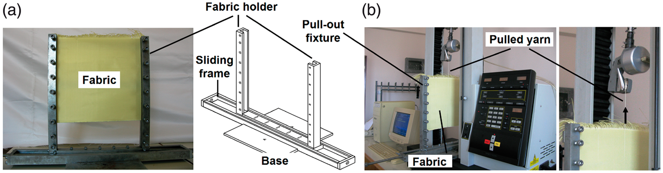
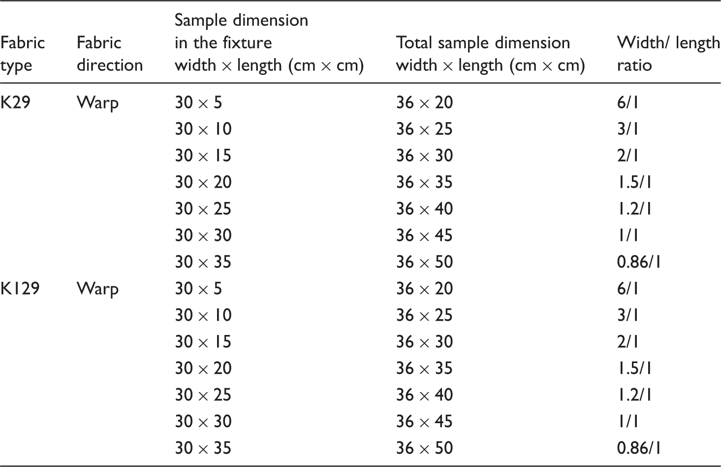
The fabric dimensions used to determine fabric shear by the pull-out test are presented in Table 2. Figure 2 shows the actual and schematic views of the fabric shear samples. The fabric width was 36 cm for the total sample dimension, and 30 cm for the sample dimension in the fixture. The pull-out direction was in the warp direction of the fabrics. The frayed yarn length in the sample was 15 cm. The fabric sample width/length ratio of 10/1 was proposed as the limit for practical measurement by Spivak [4]. For this reason, the width/length ratios of the fabric samples used for this study are also given in Table 2. The Instron 4411 pull head drew the individual yarn ends from the frayed edge of the single fabric. Schematic views of the samples before and after fabric shear by the pull-out test are shown in Figure 3.
Samples of para-aramid woven fabrics for fabric shear in various fabric lengths. Schematic views of the fabric and yarn pulled-ends for fabric shear by pull-out test; initial fabric position before fabric shear by pull-out test (left); fabric shear before crimp extension starts (right). Pull-out test dimensions of woven fabric samples

In the fabric shear test, shear displacement (formerly called fabric displacement in references [25] and [26]) and shear force were measured. Shear displacement can be defined as ‘displacement that is received under the applied tensile load on single or multiple yarn ends in the fabric just before the crimp extension starts.’ On the other hand, crimp extension can be defined as ‘yarn length that is received under theapplied tensile load on single yarn end in the fabric structure due to interlacement [26].’ In addition, the shear angle was calculated based on shear displacement. Shear rigidity was also calculated based on simple shear principles.
Results and discussion
Shear force–angle results
We can use simple shear relations to calculate the shear angle


Shear angle can be defined as

In addition, shear rigidity from the simple shear can be considered as [1]

Then, shear rigidity can be expressed as

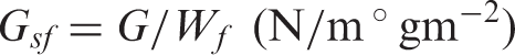
Specific shear rigidity can be defined as
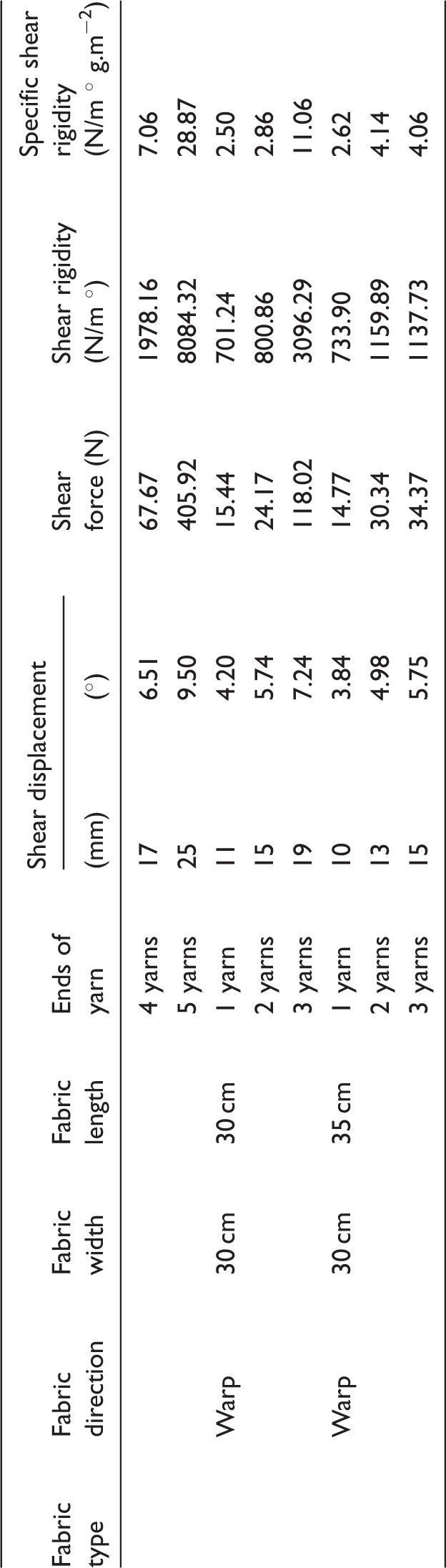
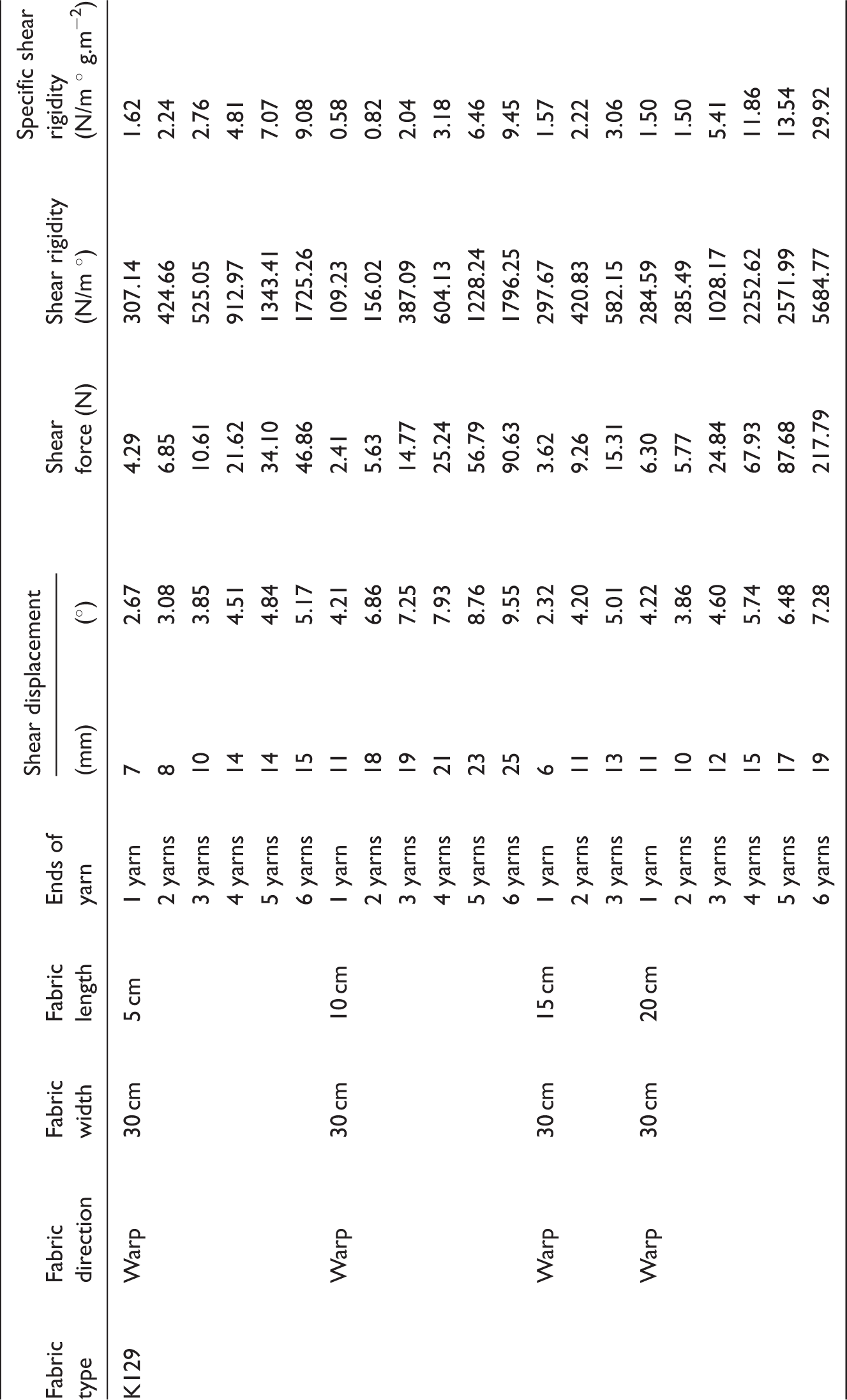
Fabric shear by the yarn pull-out test on high modulus para-aramid fabric samples was carried out and the test results are presented in Tables 3 and 4. Figure 4 shows the shear force–angle curve for shearing the fillings in the fabric during the application of tensile pulling force to the warp yarns.
Woven fabric shear force–angle curves in warp direction of fabric part A and B before crimp extension stage (Fabric: Para-aramid Kevlar K129(802), pulled ends: 6 yarns, fabric width and length: 30 × 20 cm2). Shear results of K29 fabrics by pull-out test Shear results of K129 fabrics by pull-out test


Fabric shear resulting from the yarn pull-out test was observed. Based on theseresults, the shear force–angle curve was defined and is shown in Figure 4. When the pulled yarn reaches the point just before where the crimp extension stage starts, this is defined as the maximum shear force–displacement. As seen in Figure 4, there are two regions in the fabric, called A and B, in maximum shear force–displacement. The yarn pulled region is at the center of the fabric. The A and B regions of the fabric are considered equal. In this case, the shear force–displacement curvesseen in regions A and B are equal to each other but, they are in opposite regions in the coordinate system. The tensile base pulled forces and equivalent fabric displacements were recorded. Then, fabric displacement was converted to angular displacement by using Equation (3). The shear force–angle curves obtained from theyarn pull-out test appeared to be similar to those in the simple shear and bias-extension shear methods. The initial position of the curves was proportional, but after that it showed a nonlinear behavior in which there was almost no shear angle rotation compared to the increasing high level of shear force.
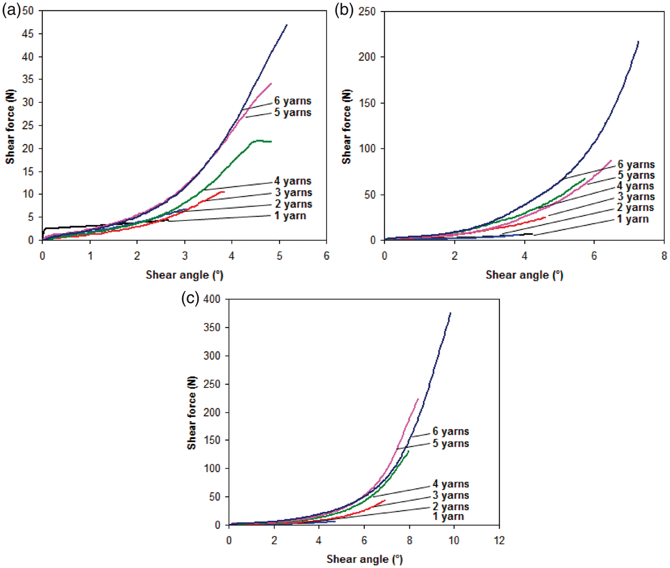
Figures 5 and 6 show the shear force–angle curve for shearing the filling in thepara-aramid fabrics during the application of tensile pulling force applied on the warp yarns, respectively. In Figures 5(a) and 6(a), the shear force–angle curves for 1-6 pulled yarn ends and sample width/length ratio (6/1) are presented. In Figures 5(b) and 6(b), the shear force–angle curves for 1-5 pulled yarn ends in K29 and 1-6 pulled yarn ends in K129 and sample width/length ratio (1.5/1) are presented. In Figures5(c) and 6(c), the shear force–angle curves for 1-3 pulled yarn ends in K29 and 1-6 pulled yarn ends in K129, and sample width/length ratios (1/1) are presented. It was observed that all shear force–angle curves and the numbers of pulled ends were proportional. When the number of pulled ends increased, the shear force–angle curves also increased.
Shear force–angle curves in warp directions of Kevlar K29 fabric for various pull-out ends. (a) Pulled ends: 1-6, fabric width: 30 cm, fabric length: 5 cm. (b) Pulled ends: 1-5, fabric width: 30 cm, fabric length: 20 cm. (c) Pulled ends: 1-3, fabric width: 30 cm, fabric length: 30 cm. Shear force–angle curves in warp directions of Kevlar K129 fabric for various pull-out ends. (a) Pulled ends: 1-6, fabric width: 30 cm, fabric length: 5 cm. (b) Pulled ends: 1-6, fabric width: 30 cm, fabric length: 20 cm. (c) Pulled ends: 1-6, fabric width: 30 cm, fabric length: 30 cm.
Effects of sample dimensions and the number of pull-out ends
The shear force–angle results for various fabric width/length ratios and the numberof pull-out ends in para-aramid fabrics are presented in Figures 7 and 8, respectively. As seen in Figure 7 and Table 3, when the number of pull-out ends in K29 fabric increased, the shear force–angle values increased in each of the fabricwidth/length ratios which were (6/1), (3/1), (2/1), (1.5/1), (1.2/1), (1/1), and (0.86/1). The increase of shear force–angle values in fabric width/length ratio (6/1), (3/1), (2/1), and (1.5/1) was high compared to those of (1.2/1), (1/1), and (0.86/1). In addition, when the fabric width/length ratios decreased, the shearforce–angle values increased due to the increasing number of sheared warpends except for fabric width/length ratios (1.2/1), (1/1), and (0.86/1).
Relationship between shear force-angle and number of pulled ends for various fabric lengths in Kevlar K29®(713) fabric (Fabric width: 30 cm). Relationship between shear force-angle and number of pulled ends for various fabric lengths in Kevlar K129®(802) fabric (Fabric width: 30 cm).

As seen in Figure 8 and Table 4, when the number of pull-out ends in K129 fabricincreased, the shear force–angle values increased in each of the fabric width/length ratios which were (6/1), (3/1), (2/1), (1.5/1), (1.2/1), (1/1), and (0.86/1). Inaddition, when the fabric width/length ratios decreased, the shear force–angle values generally increased due to the increasing number of sheared warp ends exceptfor fabric width/length ratios (2/1) and (1.2/1). On the other hand, the shear force–angle values in K29 fabric were high compared to those in K129 fabric due to high fabric density.
Effects of pull-out end position
Shear force–angle values for various pull-out end positions in the fabric sample can be calculated by means of following relations.
If the various regional shear angles were θ1 ≠ θ2 ≠ θ3 ≠ … ≠ θn, and applied forces on the pulled yarn distance in the fabric width were w1 ≠ w2 ≠ w3 ≠ … ≠ wn, and the generated shear displacements were d1 ≠ d2 ≠ d3 ≠ … ≠ dn, then the following relations can be proposed to calculate the regional shear force–angle values:


Figure 9 shows the schematic views of the tensile pull-out yarn end positions from different fabric regions. The shear force–angle curve for each region can be defined based on the data generated from the tensile testing instruments. From thedata, regional shear rigidity can also be calculated. The regional shear force–angle and rigidity values in the woven fabric can be especially important, if the fabric is transformed into varying complex geometrical shapes where local fiber fraction and porosity in the fabric could be affected. These factors influence resin infiltration during composite fabrication and the mechanical properties of the composite product. More research efforts will be spent to define the fabric’s local shearing properties and these will be published separately.
Schematic view of pull-out yarn end positions from different regions of woven fabric during pull-out test to find fabric local shear (left) and top portion of various regional shear displacements and angles.
Shear rigidity results
Fabric shear rigidity on para-aramid fabrics was found to be based on the relationships defined in the shear force–angle results sub-section of the text. The fabric shear rigidity results are presented in Tables 3 and 4.
The shear rigidity results for various fabric width/length ratios and the number of pull-out ends in the para-aramid fabrics are presented in Figures 10 and 11, respectively. As seen in Figures 10 and 11 and Tables 3 and 4, when the number of pull-out ends in K29 and K129 fabrics increased, the shear rigidity values increased in all fabric width/length ratios of K29 and K129 fabrics. In addition, when the fabric width/length ratios decreased, the shear rigidity values generally increased due to the increasing number of sheared warp ends. This indicated that fabric sample dimension and the number of pulled ends greatly influenced fabric shear rigidity. On the other hand, the shear rigidity values in K29 fabric were high compared to those in K129 fabric due to high fabric areal density.
Relationship between shear rigidity and number of pulled ends for various fabric lengths in Kevlar K29®(713) fabric. Relationship between shear rigidity and number of pulled ends for various fabric lengths in Kevlar K129®(802) fabric.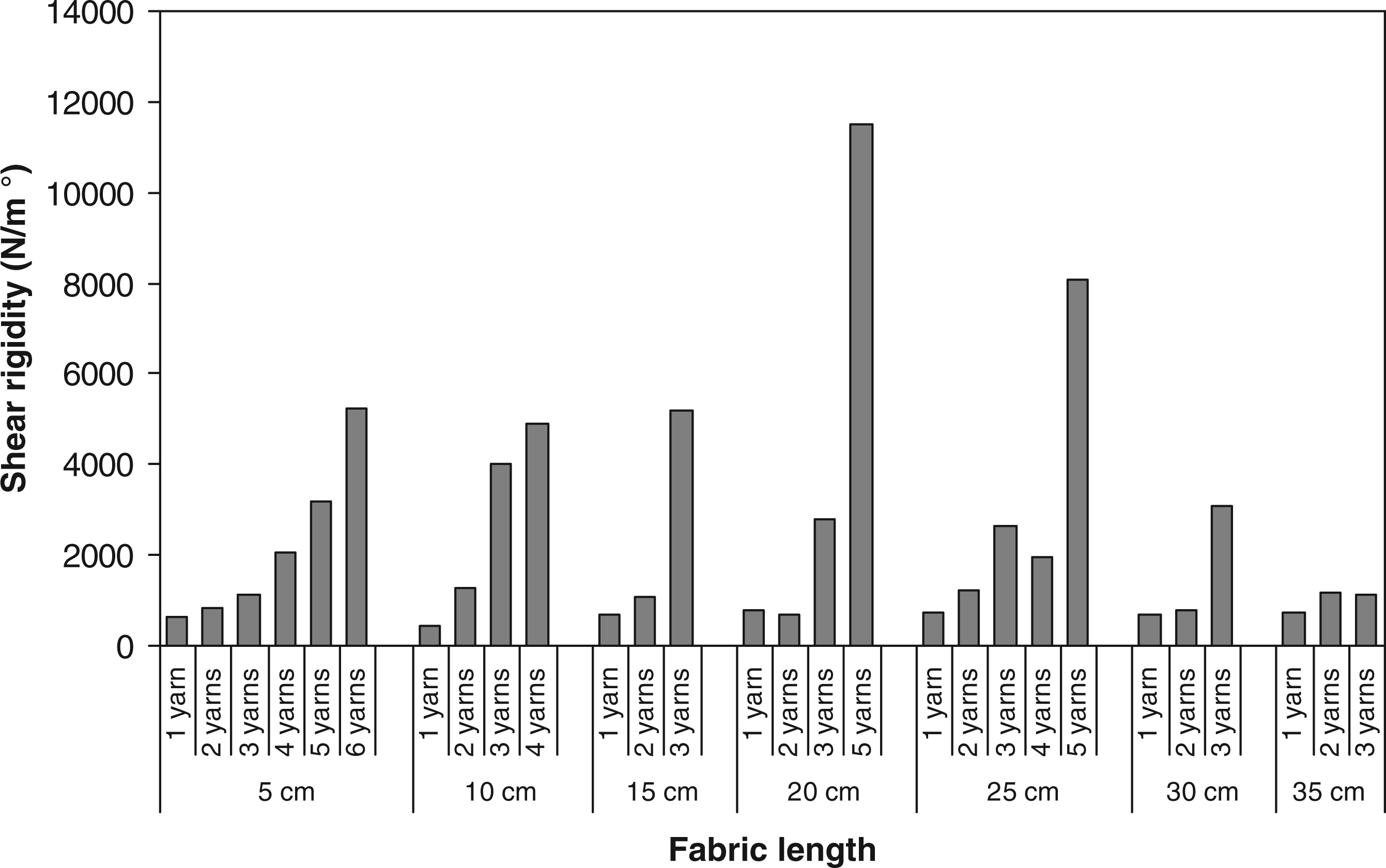

Specific shear rigidity in para-aramid fabrics was calculated based on the relationships defined in the shear force–angle results sub-section of the text. The fabric specific shear rigidity results are presented in Tables 3 and 4, and Figure 12.
Relationship between specific shear rigidity and number of pulled ends for various woven fabric types (Fabric width: 30 cm, Fabric length: 20 cm).
As seen in Figure 12 and Tables 3 and 4, when the number of pull-out ends increased, the specific shear rigidity values increased. On the other hand, the specific shear rigidity of K29 was higher than that of K129 for all pulled yarn ends. The maximum specific shear rigidity in width/length ratio (1.5/1) was obtained in K29 fabric at 5 yarn pulled ends.
Shear jamming results
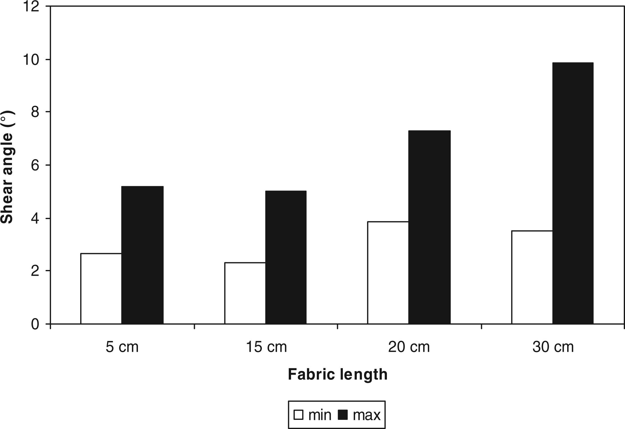
The shear jamming results for various fabric width/length ratios and the number of pull-out ends in K29 and K29 fabrics are presented in Figures 13 and 14. As seen in Figures 13 and 14 and Tables 3 and 4, when the number of pull-out ends increased, the shear angle values increased in each of the fabric width/length ratios (6/1), (2/1), (1.5/1) and (1/1). The minimum shear angle in all fabrics was obtained when the number of pulled ends was 1, whereas the maximum shear angle was obtained when the number of pulled ends was 3-6. The shear jamming angle ranged from 3.84° to 12.57° for K29 fabric and 2.32°-10.59° for K129 fabric. The difference between shear jamming angles was around 8.73° for K29 fabric and 8.27° for K129 fabric. On the other hand, the maximum shear angle value in K29 fabric was high compared to that in K129 fabric except for width/length ratio (1/1).
Shear angle jamming in Kevlar 29®(713) woven fabric for various fabric lengths (Fabric length: 5 cm, pulled ends: 1-6, fabric length: 15 cm, pulled ends: 1-3, fabric length: 20 cm, pulled ends: 1-5 and fabric length: 30 cm, pulled ends: 1-5). Shear angle jamming in Kevlar 129®(802) woven fabric for various fabric lengths (Fabric length: 5 cm, pulled ends: 1-6, fabric length: 15 cm, pulled ends: 1-3, fabric length: 20 cm, pulled ends: 1-6 and fabric length: 30 cm, pulled ends: 1-5).
Conclusions
Para-aramid fabrics were tested to define fabric shear by the pull-out method. During shear testing by pull-out, it was found that fabric width/length ratio and the number of pull-out ends were important testing parameters. In addition, fabric shear depended on fabric density.
Shear strength increased when the fabric width/length ratio decreased and the number of pulled ends increased. It was found that the shear force–angle values in K29 fabric were high compared to those in of K129 fabric due to high fabric density.
Fabric width/length ratio and the number of pull-out ends influenced fabric shear rigidity. Generally, when the number of pull-out ends increased, the shear rigidity values increased. On the other hand, when the fabric width/length ratios decreased, the shear rigidity values increased. Therefore, the number of pull-out ends and fabric width/length ratios influenced fabric shear rigidity. The shear rigidity values in K29 fabric were high compared to those in K129 fabric due to high fabric areal density.
Shear jamming angles were found to be based on the number of pulled ends. The maximum and minimum shear angle in K29 and K129 fabrics were generated by 3-6 and 1 ends, respectively. On the other hand, fabric local shearing properties could be identified by pulling the yarn ends in various regions of the fabric which was especially important for fabric handling during formation. The results generated from this study showed that fabric shear could be measured by the yarn pull-out test.
Footnotes
Acknowledgements
The author would like to thank DuPont de Nemours International S.A. for their assistance in this research work. The author also thanks Research Associate Mr. Mahmut Korkmaz and Research Assistant Miss. Gaye Yolacan for helping during the preparation of the manuscript.
Funding
This research received no specific grant from any funding agency in the public, commercial, or not-for-profit sectors.