
Abstract
Underground copper (Cu)-based infrastructure, including pipelines, cables, wiring and large-scale appliances are frequently situated near electrical sources, including power sources, railway systems, cathodic protection devices and domestic circuits. Currents may ‘stray’ from electrical circuits associated with these sources into surrounding soil. Such stray currents can create voltage differences across the Cu assets, thus leading to corrosion. In this study, we aim to experimentally simulate stray current corrosion of Cu to mimic real-world conditions using a laboratory electrochemical cell with different types of soils. The stray current corrosion was achieved by applying voltages between two titanium (Ti) electrodes with Cu samples placed in between them. This cell-within-cell setup was employed to investigate the influence of soil conductivity and the distance between electrodes and the electrical source on the stray current corrosion of Cu.
Introduction
Stray currents originating from various sources such as electric power systems, transportation systems and cathodic protection systems can inadvertently flow through the ‘ground’ (soil, concrete structures and the conductive environment) and interact with buried metallic assets, resulting in what is known as ‘stray current’ corrosion of these assets.1–8 This phenomenon poses a significant challenge to infrastructure, leading to substantial economic losses and compromised structural integrity. In such scenarios, the metallic asset essentially exists within an electric field between the stray current ‘source’ and ‘sink’. These terms refer to points in the electrical circuit where stray currents enter and flow back to the designated circuit, respectively. Stray currents naturally follow the path with the least resistance, which may involve flowing through soil, other conducting metallic structures, or reinforcing elements within the environment.1,3 Electronic currents flow through metallic elements, while ionic currents travel through soil or other media (referred to as ionic environments). These are driven by the voltage difference between the ‘source’ and ‘sink’. Parts of the metallic asset located closer to the stray current ‘source’ generally tend to become cathodic relative to other regions, whereas those nearer to the ‘sink’ tend to become anodic.1,3 These voltage differences across the metallic asset contribute to the process of stray current corrosion. Steel assets are known to be vulnerable to stray current corrosion, especially in infrastructure exposed to stray currents from nearby power systems or transit networks. Over the past decade, several studies have examined the effects of stray current corrosion on steel-based materials in soil, both in field and in laboratories.1,9–20 Several researchers have developed methods to investigate stray current corrosion of steel using novel electrochemical set-ups and techniques.21–23 Copper (Cu) is extensively utilised in urban infrastructure due to its high electrical conductivity, affordability, thermal properties and corrosion resistance, and thus, there have been several previous studies on Cu corrosion in soils.24,25 Cu/Cu alloy-based assets, such as pipelines, electrical equipment, cables and wires, are buried in soil and often located near electrical sources, thus, making them susceptible to stray current corrosion. Limited knowledge exists on stray current corrosion of Cu/Cu alloys in soils.
Soils themselves are complex media that initiate corrosion through various mechanisms, and the corrosion rate of a metal can vary significantly across different soils.26–31 Soils consist of particles with varying particle sizes and levels of compaction, leading to different levels of porosity or ‘free volume’ available for water and oxygen ingress which could trigger corrosion of buried metallic structures. 27 Additionally, soils exhibit different water retention capacities. 27 For instance, clay- and loam-based soils commonly found in inland Victoria (Australia) retain more water compared to sandy soils along the coast. 27 Soil conductivity increases with moisture content, with higher moisture-carrying soils (clay, loam, silt) driving higher corrosion rates of metals when compared to less conductive sandy soils. 27 However, there is limited laboratory research on stray current corrosion of Cu in soils with varying conductivities. Such studies could help identify the mechanisms of stray current corrosion of Cu and determine how anodic and cathodic sites form within stray current fields based on soil conductivity. Understanding Cu/Cu-alloy performance in stray current fields is crucial for developing mitigation strategies to ensure the durability and safety of metallic infrastructure systems in the long term. Laboratory-scale data can serve as benchmark data and be used alongside modeling approaches to simulate stray current fields and current distribution near stray current sources or sinks,32–35 assisting in predicting corrosion rates of Cu or other metals under such conditions.
In this study, we employed a cell-within-cell approach to investigate stray current corrosion of Cu in soils. In this approach, Cu samples were placed in an electrochemical cell containing two mixed metal oxide coated titanium (Ti) mesh electrodes, using different soils as electrolytes. Stray current fields were induced by applying varying voltages between the two Ti electrodes, with one Ti electrode thus serving as the anode (or ‘source’) and the other as the cathode (or ‘sink’). The work investigates the effects of soil conductivity and distance from the stray current source on corrosion of Cu. It also analyses voltage drops and distribution of anodic/cathodic sites across Cu samples that is located in a stray current field. These are then correlated with soil conductivity and analysed based on distance from the ‘source’ and ‘sink’ electrodes. The voltage drops associated with stray current flow through soils, and their influence on corrosion are also elucidated in this study.
Experimental
Electrochemical cell set-up
A rectangular box made of polymeric material was used, with known dimensions (see Figure 1). It was filled with various test soils mixed with saline fluids. Two mesh Ti electrodes were then immersed into the medium, with one serving as the anode or ‘source’ for stray currents, and the other as the cathode or ‘sink’. A saturated calomel reference electrode (SCE) was employed to monitor the voltages of the Ti electrode acting as the anode or ‘source’. A Bio-Logic VMP3 potentiostat was utilised to apply different voltages, with varying patterns, to the ‘source’ Ti electrode. These voltage patterns were designed to replicate measurements taken in soil adjacent to a railway line in Victoria, Australia, where stray current fields are often measured.
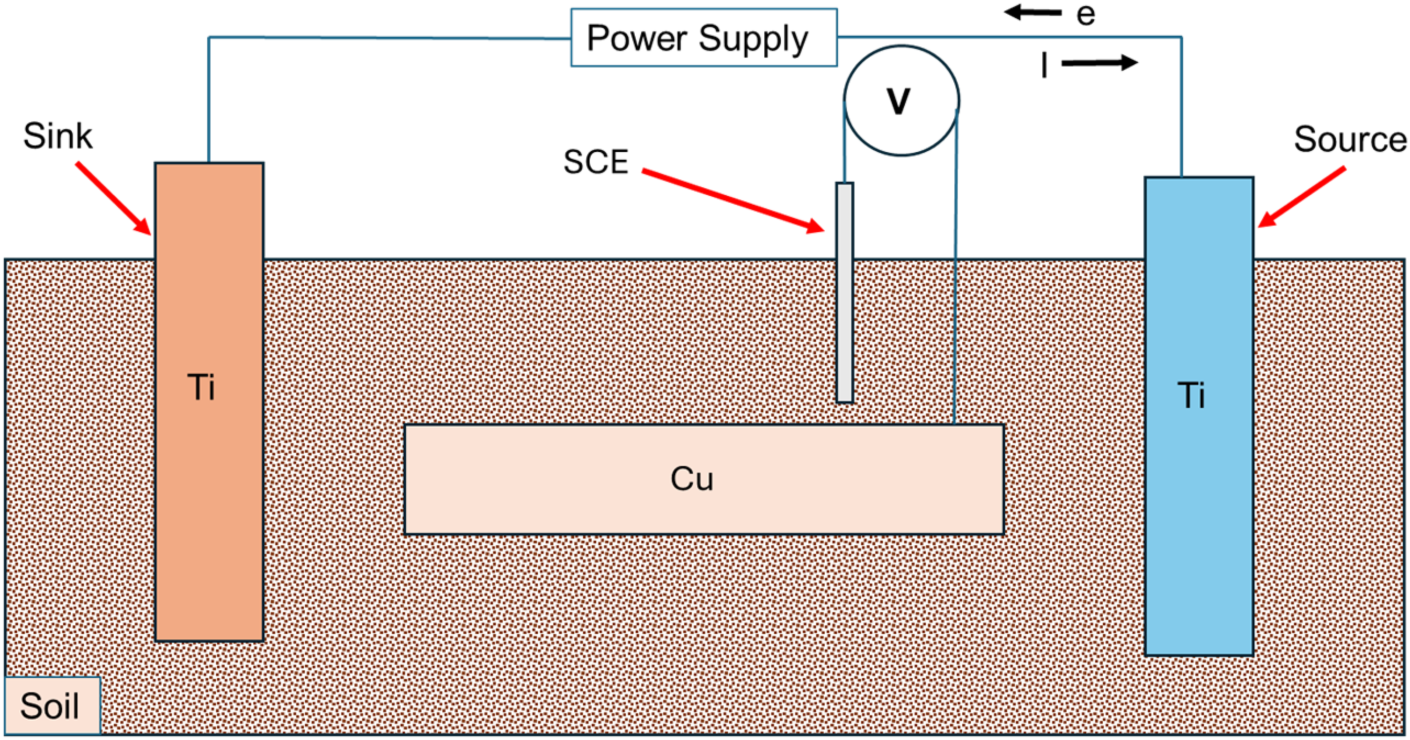
The cell-within-cell electrochemical set-up that is used to measure stray current corrosion of Cu samples, placed between ‘source’ and ‘sink’ Ti electrodes. The source electrode is the anode and sink the cathode. The voltage of the ‘source’ Ti electrode is varied (vs VSCE) between 0 and 5 V, representing ‘on’ and ‘off’. The reference electrode used to measure this is not shown in the schematic. Simultaneously, voltages of Cu are measured using a second reference electrode (shown). The soil and sizes of Cu samples are varied to identify the influence of soil conductivity and source-sample distance on stray current corrosion mechanisms.
Cu alloy (UNS C12100) samples of different lengths (but similar breadth and thickness) were positioned between the Ti electrodes to achieve varying distances from the source electrode. Another SCE was used concurrently to monitor voltages at the Cu sample while voltage was applied to the ‘source’ electrode. These voltage patterns were applied continuously for 72 hours, and the resulting weight loss of the Cu samples was estimated using standard methods. The experiments were performed multiple times to ensure reproducibility and reliability. A reference electrode is used to measure voltages at different sites over Cu samples placed in an electric field, this is relatively straightforward and simple – and any errors will be clearly evident in the measurements.
Electrochemical testing
The voltage patterns shown in Figure 2 were applied between the ‘source’ and reference electrode (SCE). Simultaneously, voltages were measured at five different positions over the Cu electrode (Figure 3). These include five positions, labelled as 1, 2, 3, 4 and 5 in Figure 3. Here, positions 1 and 2 represent regions closest to the ‘sink’ and ‘source’, respectively. Position 3 is near the centre of the Cu sample and thus equidistant from the source and sink. Positions 4 and 5 are near the edges and are closer to ‘sink’ and ‘source’, respectively. The voltages measured at these positions indicate how different regions of the Cu electrode become polarised, in stray current fields. This helps in estimating which regions become anodic/cathodic and are thus most/least prone to corrosion, respectively.
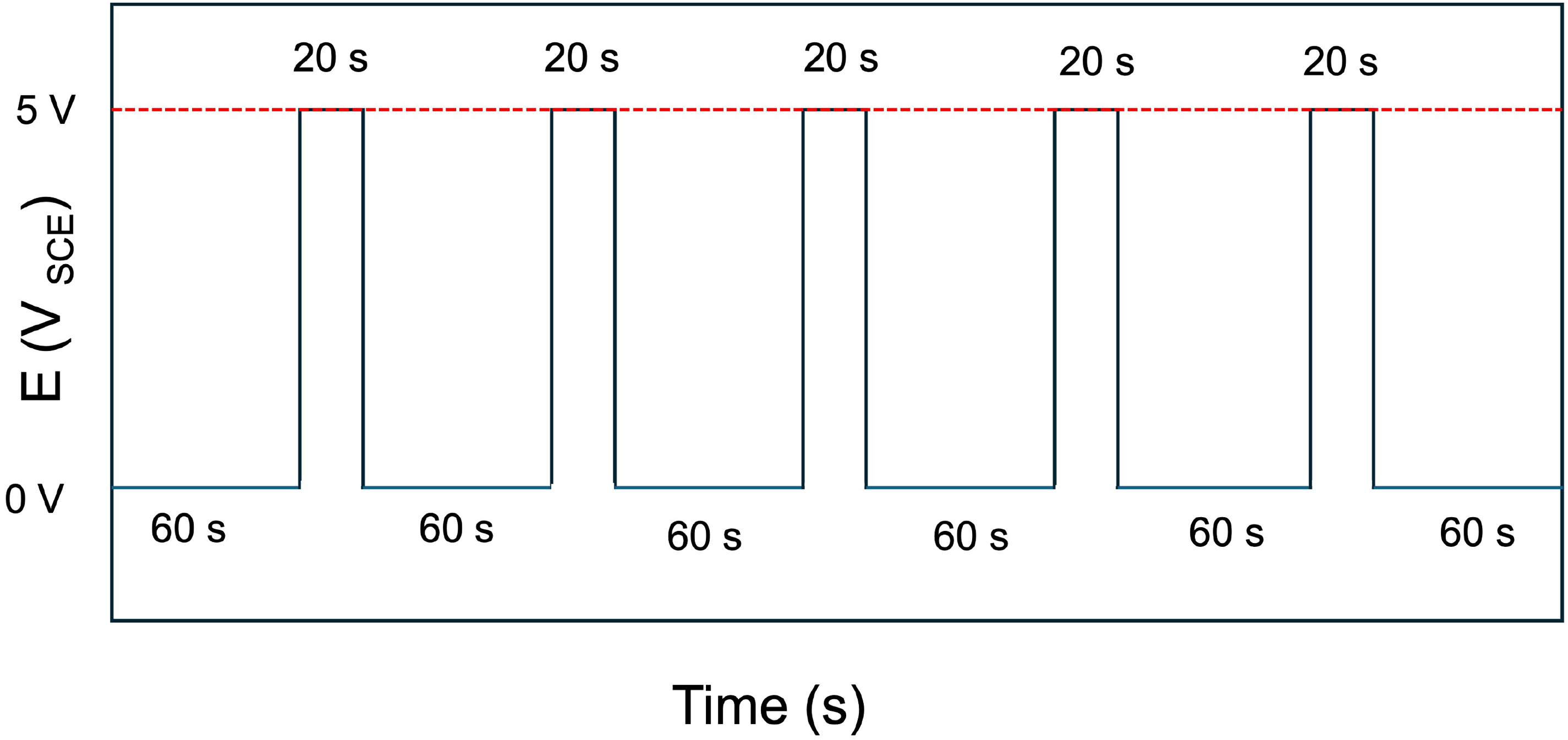
Voltage patterns applied to the ‘source’ Ti electrode (anode), resulting in chronoamperometric currents flowing between the ‘source’ and ‘sink’ electrodes. The voltage was varied between 0 and 5 VSCE. The voltage patterns were applied in ‘on’ and ‘off’ cycles, where it was kept 5 VSCE for 20 s in the ‘on’ cycle and kept at 0 VSCE for 60 s in the ‘off’ cycle.
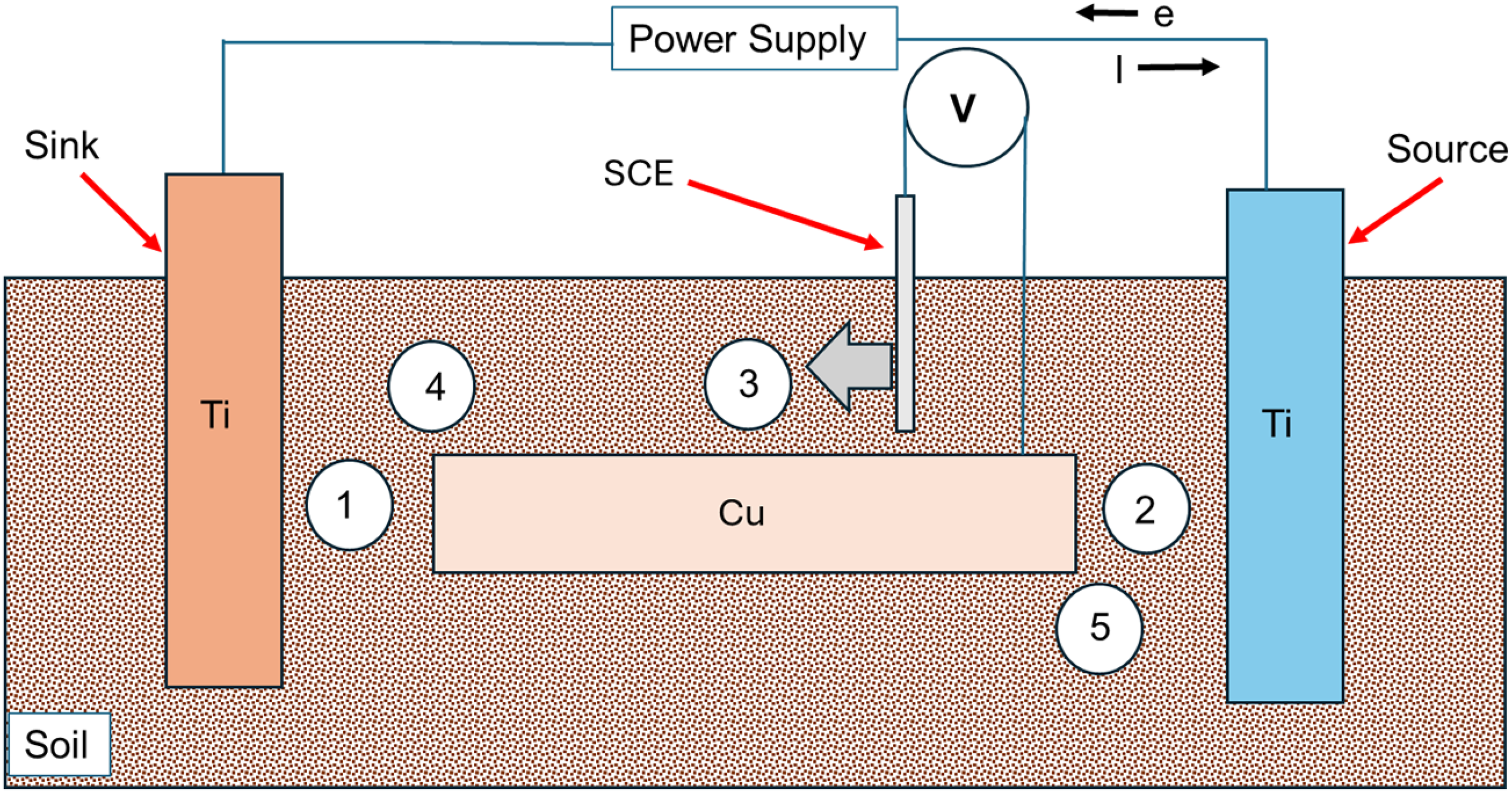
The voltage of the ‘source’ Ti electrode is varied (vs VSCE) between 0 and 5 V, as shown in Figure 2, and simultaneously the voltages of Cu are measured using a reference electrode at different positions labelled as 1, 2, 3, 4 and 5, respectively. Positions 1 and 5 are nearer to the ‘source’ and ‘sink’, respectively. Position 3 is approximately equidistant from source and sink. Additional measurements were made at positions 4 and 5.
Effect of distance between Cu and source/sink electrodes
Cu samples with different lengths (10 mm, 50 mm and 100 mm) were placed between the ‘source’ and ‘sink’ electrodes (Figure 4) and subjected to stray current fields resulting from applied voltage to the ‘source’ Ti electrode (refer Figure 2). The voltage drop estimated based on voltage measurements at positions 1, 2, 3, 4 and 5 (Figure 3) were identified. This served to identify the effect of Cu-source distance on voltage drops, and their influence on Cu corrosion.
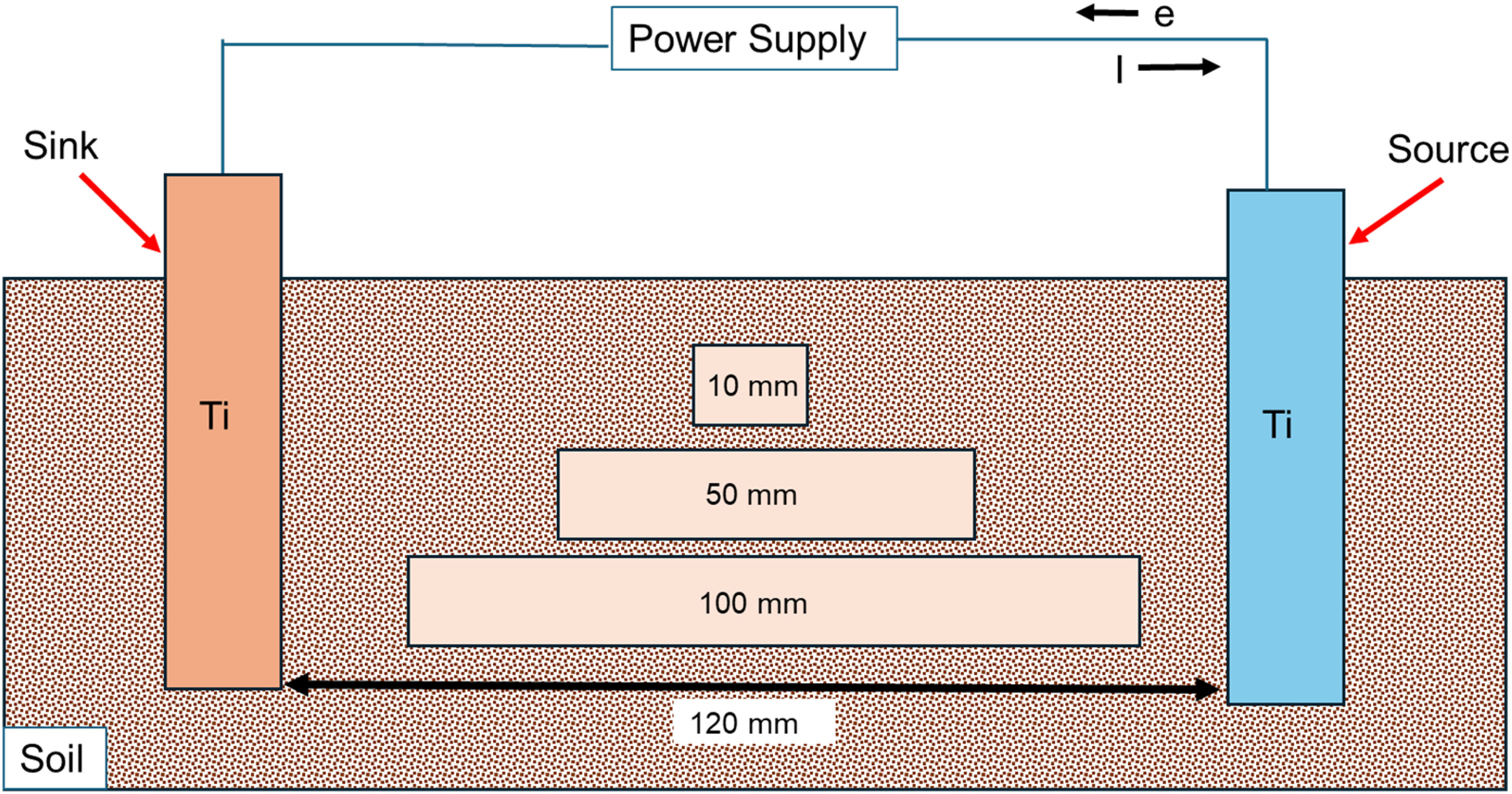
The voltage of the ‘source’ Ti electrode is varied (vs VSCE) between 0 and 5 V, as shown in Figure 2, and simultaneously the voltages of Cu are measured using a second reference electrode. Different Cu samples are used, with varying lengths as indicated in the figure. This leads to different ‘source’-sample distances. The distance between the 10 mm Cu sample and the ‘source’ electrode is 55 mm. For the 50 mm sample, it's 35 mm and for the 100 mm sample it's 10 mm.
Effect of soil electrical conductivity
Four different soils were used as the testing media (electrolyte). A small known amount of additional electrolyte (0.01 M or 0.1 M NaCl) was mixed into the soils, to achieve stable ionic conductivity. The degree of saturation (Sr) of soils achieved by mixing solution with soils, 15 was kept at 0.6. The soils that were used are sand, clay and clay loam. Clay loam was made by mixing 35 wt-% sand, 35 wt-% clay and 30 wt-% silt. 21 The conductivities of these soils were measured using a handheld soil electrical conductivity tester (Soil Test Kit, Hanna Instruments). The effect of soil conductivity on voltage drops at the Cu electrode, was estimated using voltage measurements at the different points (as mentioned above) to ultimately determine their influence on stray current corrosion of Cu.
Results and discussion
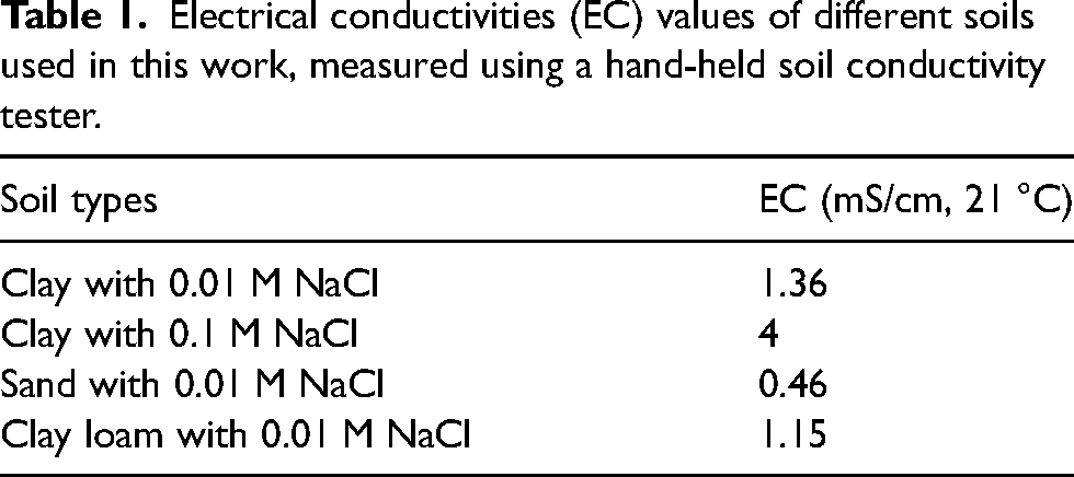
The electrical conductivities (EC) of different soil mixtures used in this work, namely clay with 0.1 M NaCl, clay with 0.01 M NaCl, sand with 0.01 M NaCl and clay loam with 0.01 M NaCl are shown in Table 1. Clay-based soils have higher water retention capacities, and correspondingly have higher EC values when compared to sand. Addition of more concentrated NaCl solution also increases conductivity.
Electrical conductivities (EC) values of different soils used in this work, measured using a hand-held soil conductivity tester.
Voltage drops across Cu samples in the stray current field
The voltages of Cu recorded when placed in clay with 0.1 M NaCl with Sr = 0.6, and between the Ti electrodes that were subject to ‘on’ and ‘off’ cycles are shown in Figure 5(a)–(e). During the ‘on’ cycle, 5 V is applied vs VSCE to the ‘source’ electrode for 20 s, and during the ‘off’ cycle 0 V is applied for 60 seconds (refer Figure 2). The length of the Cu sample here is 100 mm, and its distance from the ‘source’ is 10 mm. The voltages of Cu were determined at different positions (as shown in Figure 3). At position 1, which is nearer to the Ti cathode or ‘sink’, Cu experiences anodic polarisation during ‘on’ cycles, with voltage close to approximately 1500 mV being measured. Interestingly, close to the Ti anode or ‘source’, Cu experiences cathodic polarisation with its voltage reaching close to −3000 mV. This validates at a laboratory scale, that in stray current fields, regions of Cu that are closest to the ‘source’ (or anode) tend to become the cathode, whereas regions close to the ‘sink’ become the anode. Importantly, a voltage drop develops across the Cu sample which drives stray current corrosion. This voltage drop is determined to be approximately 4500 mV, which is the difference between voltages measured during the ‘on’ cycles, at positions 1 and 2. At the middle of the Cu sample (position 3), a lower cathodic voltage is measured during the ‘on’ cycle. This is understandable as an electric field/voltage drop develops across the entire Cu sample, and at the lowest in the middle. Similar measurements were made at positions 4 and 5. These are consistent with measurements made at positions 1 and 2.
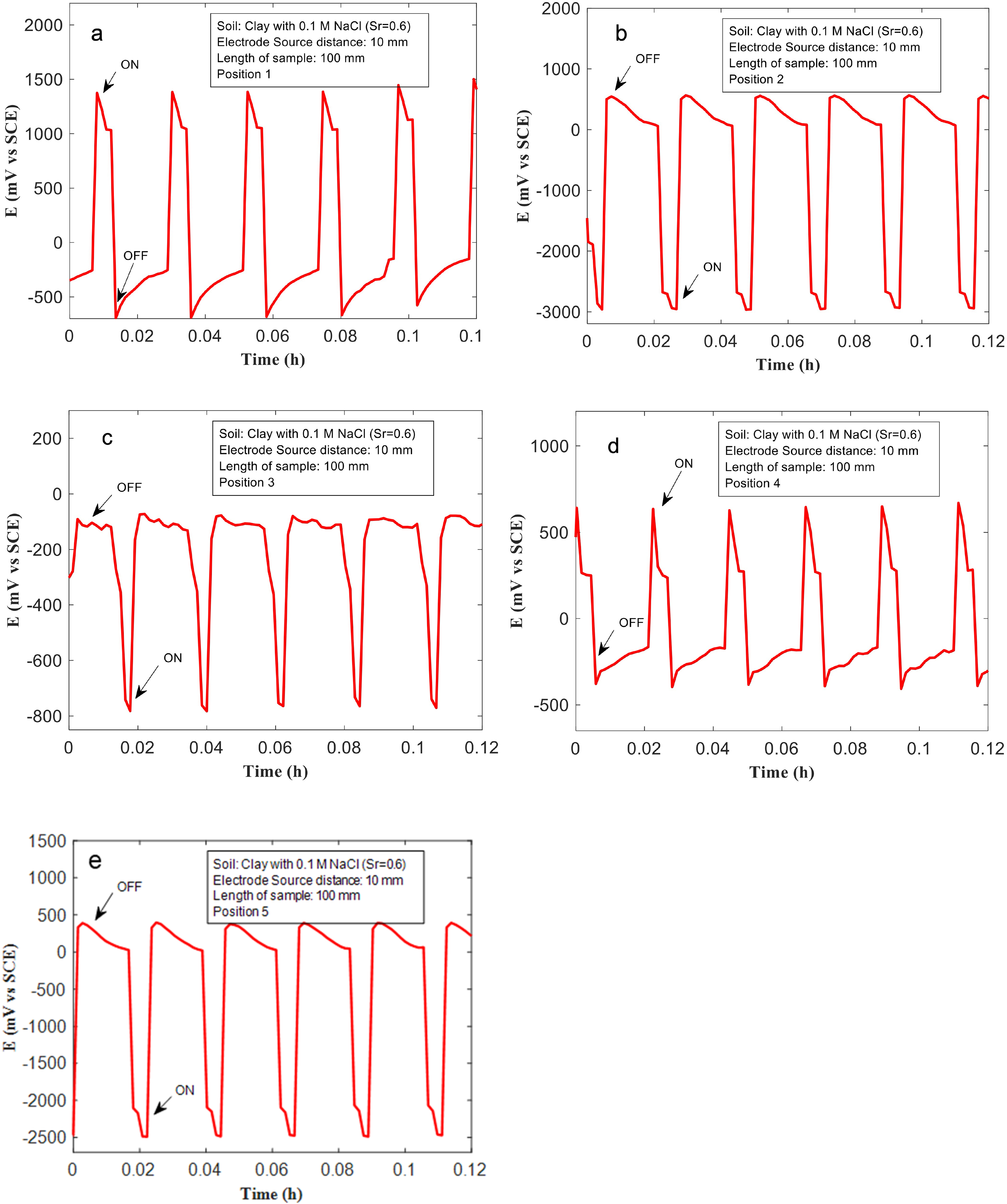
(a–e) The voltages measured at the Cu sample with length 100 mm, and 10 mm from the ‘source’ (anode), at different positions, in a soil containing clay mixed with 0.1 M NaCl, and saturation ratio (Sr) = 0.6.
Effect of ‘source’-sample distance on voltage drop
The Cu samples (with different lengths) were placed at different distances from the ‘source’ Ti electrode (Figure 3). The effects of ‘source’-sample distance on the associated voltage drops across the Cu samples, and consequently, the extent of anodic and cathodic polarisation experienced by different regions of the Cu samples, are shown in Figures 6–8. In Figure 6, voltage patterns recorded during ‘on’/‘off’ cycles at different positions (1 and 2) for a 10-mm-long Cu sample, placed 55 mm away from the source are shown. This corresponds to the smallest Cu sample investigated in this study, and the furthest distance from the ‘source’ electrode (Figure 3). The soil used for testing was clay mixed with 0.01 M NaCl (Sr: 0.6). At regions of the Cu sample, closer to the ‘sink’, during the ‘on’ cycles, voltages close to 800 mV (vs VSCE) were recorded. Similarly, Cu regions nearer to the ‘source’ were polarised cathodically near −500 mV (vs VSCE), during the ‘on’ cycle. The voltage drop across both ends of the Cu sample is therefore approximately 1300 mV, which is substantially different compared to that measured in the previous section (∼4500 mV), where a longer Cu sample placed closer to the ‘source’ electrode was used. Assuming that the length of the Cu sample does not significantly impact the voltage drop (given that Cu is an excellent electrical conductor), it is proposed that the distance between the ‘source’ and Cu sample controls the voltage drop across the Cu sample. This is further validated from data recorded over other Cu samples positioned at different distances from the ‘source’ electrode (Figures 7 and 8). For the 50-mm-long sample that is placed 35 mm away from the source. The voltage measured at position 1 is approximately 1200 mV, and at position 2 it is approximately −2500 mV during ‘on’ cycles (Figure 7(a) and (b)). The voltage drop therefore is approximately 3700 mV, which is much higher than that measured across the 10 mm sized sample. For the 100 mm sized sample, placed much closer to the ‘source’, the voltage measured at position 1 is approximately −2800 mV, and at position 2 it is close to 1500 mV (Figure 8(a)-(b)). The voltage drops across the Cu sample is 4300 mV, which is the highest for the different sized Cu samples and configurations tested here. This set of results indicates that metallic assets that are nearer to either the stray current ‘source’ or ‘sink’ experience larger voltage drops across them and are more prone to severe corrosion from stray current fields.
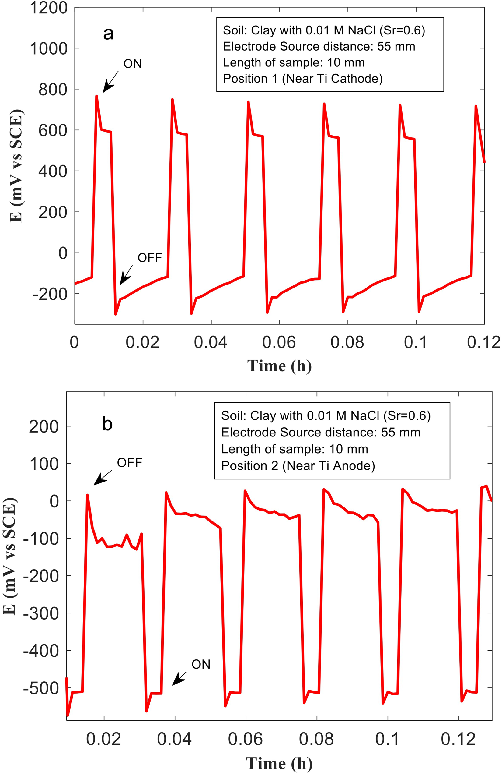
(a, b) The voltages measured at the Cu sample with length 10 mm, and 55 mm from the ‘source’ (anode), at different positions in clay mixed with 0.01 M NaCl, and saturation ratio (Sr) = 0.6.
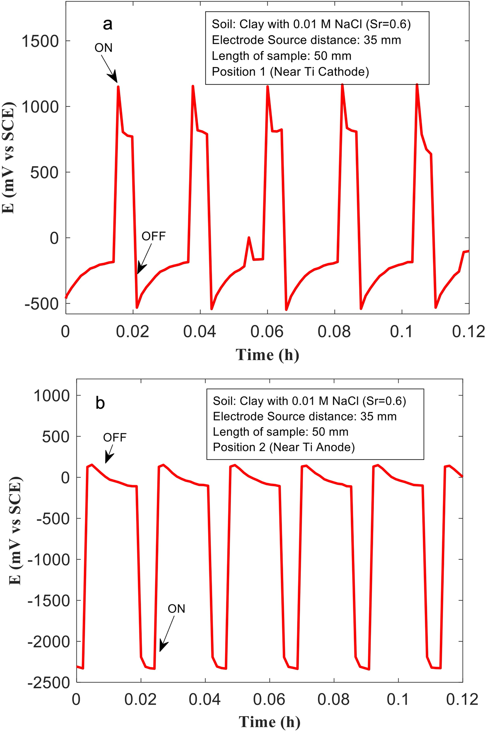
(a, b) The voltages measured at the Cu sample with length 50 mm, and 35 mm from the ‘source’ (anode), at different positions in clay mixed with 0.01 M NaCl, and saturation ratio (Sr) = 0.6.
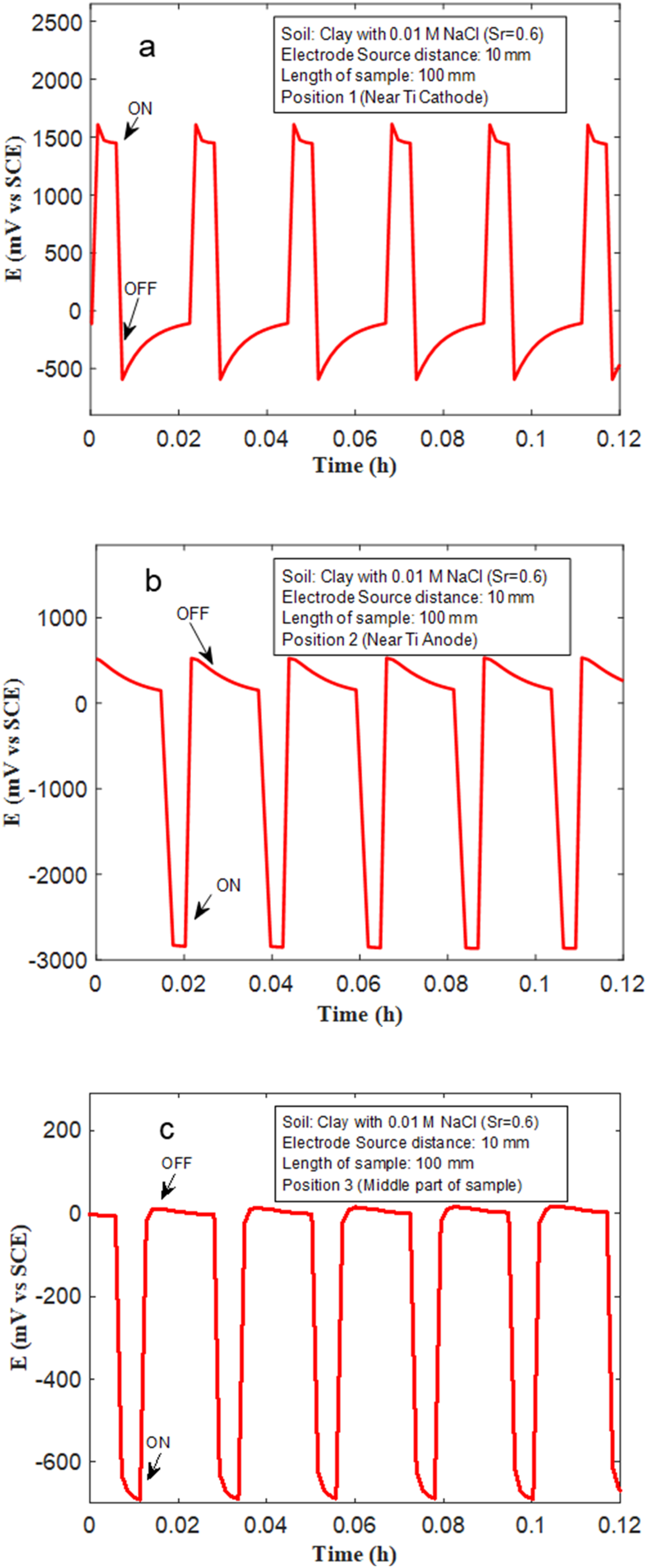
(a–c) The voltages measured at the Cu sample with length 100 mm, and 10 mm from the ‘source’ (anode), at different positions in clay mixed with 0.01 M NaCl, and saturation ratio (Sr) = 0.6.
Effect of soil conductivity on voltage drop
The effects of soil texture type, and soil conductivity on voltage patterns (and voltage drops) across Cu samples, placed in stray current fields are shown in Figures 8–10. The measurements were performed in clay, sand and clay loam mixed with 0.01 M NaCl, with Sr = 0.6. The length of the Cu samples used in these experiments was 100 mm, and the distance from the Ti source was fixed at 10 mm. Clay mixed with 0.1 M NaCl and 0.01 M NaCl have the highest electrical conductivity (Table 1). Correspondingly, higher voltages are measured at Cu samples placed in clay-based soils during ‘on’ cycles, at various positions both near to the ‘source’/'sink’ and, at position 3 which is equidistant to the source and sink. In clay mixed with 0.1 M NaCl a voltage close to approximately −800 mV was measured (Figure 5(c)). Similarly, in clay mixed with 0.01 M NaCl, at position 3, voltages close to −500 mV are measured (Figure 8(c)). In sand and clay loam, the voltages measured at position 3 are much lower. They are nearer to −150 mV (Figures 9(c) and 10(c)). The voltages measured at positions 1 and 2, in sand and clay loam are also much lower than that measured in clay. In sand, at position 1, voltages close to 1000 mV were measured, whilst in clay loam at position 1, voltages close to 1000 mV were measured (Figures 9(a) and 10(a)). At position 2, the voltages measured in sand and clay loam are approximately -2200 and −2500 mV, respectively (Figures 9(b) and 10(b)). The voltage drops in sand and clay loam are therefore estimated to be 3200 mV and 3500 mV, respectively, which are lower than that measured in clay (4500 mV), under similar experimental conditions. This indicates that conductivity of soil plays a major role, in controlling voltage drops in stray current fields and correspondingly stray current corrosion mechanisms in Cu. When the conductivity of the soil environment is low, the voltage drop (IR) or ohmic resistance from the environment is higher, this leads to lower polarisation of Cu samples which is placed within the soil, and correspondingly, lower voltage drop across the Cu sample.
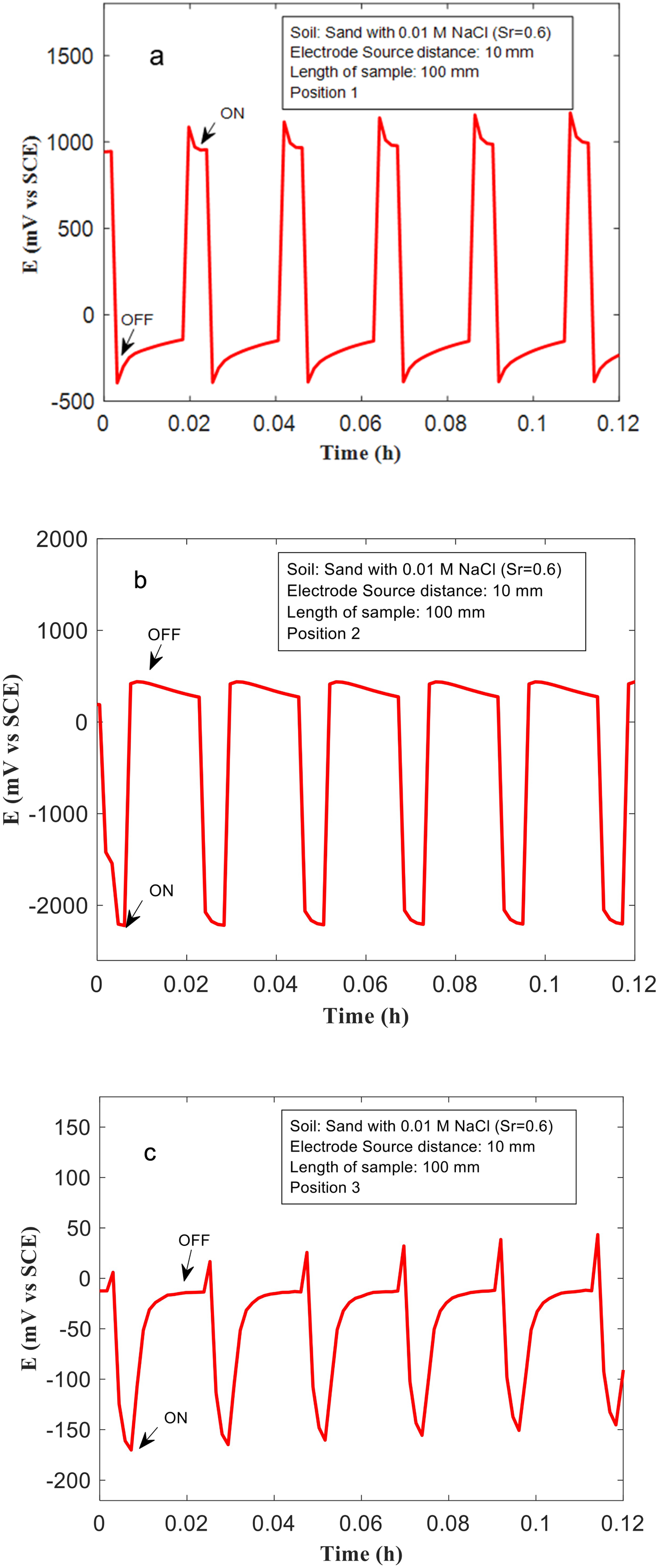
(a–c) The voltages measured at the Cu sample with length 100 mm, and 10 mm from the ‘source’ (anode), at positions 1, 2, and 3 in a soil containing sand mixed with 0.01 M NaCl, and saturation ratio (Sr) = 0.6.
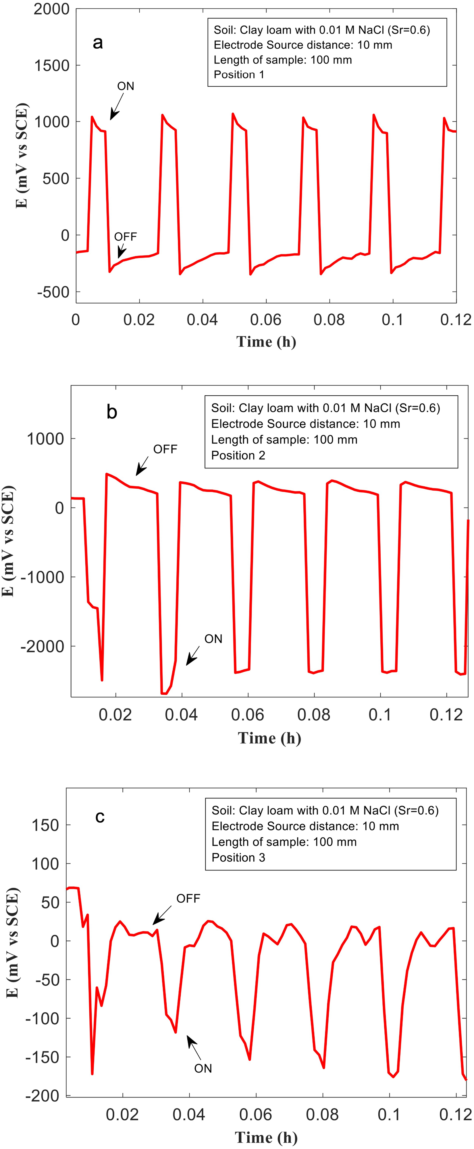
(a–c) The voltages measured at the Cu sample with length 100 mm, and 10 mm from the ‘source’ (anode), at positions 1, 2 and 3 in a soil containing clay loam mixed with 0.01 M NaCl, and saturation ratio (Sr) = 0.6.
Weight loss measurements and their correlation with soil conductivity and voltage drop
Weight loss measurements were performed on Cu samples that were subject to voltage patterns shown in Figure 2, for 72 hours. These measurements were performed for Cu samples that were at different ‘source’-'sample’ distances, with applied voltages corresponding to Figure 6 and 8. This was also performed in different soil environments, for a Cu sample with length 100 mm and kept 10 mm away from the source (with applied voltages corresponding to Figures 5, 8, 9 and 10). The weight loss data and voltage drops (estimated from Figures 6 and 8) corresponding to measurements made on Cu samples with different ‘source’-'sample’ distances in clay with 0.01 M NaCl is presented in Figure 11. Similarly, weight loss data in different soil environments after application of voltage patterns is shown in Figure 12. Weight loss from stray current corrosion is correlated to the voltage drop across the Cu sample (Figure 11). As expected, increasing voltage drop across the Cu sample results in increased weight loss. Increased voltage drop implies that there is increased anodic and cathodic polarisation of Cu, at the respective anodic and cathodic regions. This leads to more severe corrosion and thus, increased weight loss. The Cu sample that is farthest away from the source, and which is also the smallest used in this study experiences the lowest voltage drop and has the lowest weight loss (Figure 11). The longest Cu sample and closest to the source has the highest weight loss after 72 hours (Figure 11). The effect of soil conductivity on weight loss is shown in Figure 12. As expected, weight loss after 72 hours increases with increasing soil electrical conductivity. The increased conductivity enables efficient anodic/cathodic polarisation of Cu samples, when placed in the electric field between the Ti electrodes. There is limited ohmic voltage drop in conductive soils, and this therefore tends to increase corrosion.
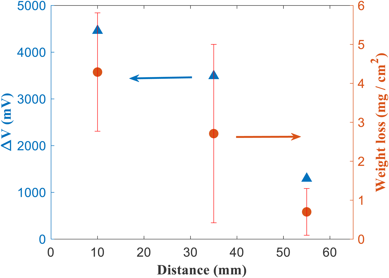
Voltage drop across Cu samples of different lengths in soil containing clay with 0.01 M NaCl. The voltage drop is plotted against the distance between the Cu sample, and the ‘source’ electrode. The corresponding weight loss data from the same samples obtained after applying the voltage patterns (shown in Figure 2) for 72 hours is also shown. This enables one to correlate the voltage drop, against the weight loss for Cu samples experiencing stray current corrosion.
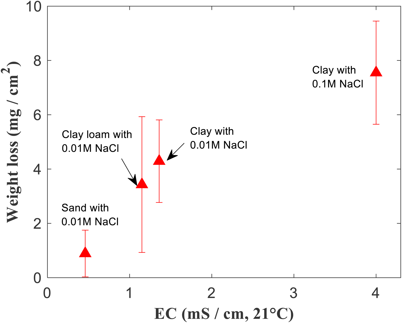
Weight loss values of Cu obtained after application of voltage patterns to Ti electrodes for 72 hours (refer Figure 2), plotted against electrical conductivity values of the 4 different types of soils used in this study.
The body of this work shows using a laboratory set-up how voltage differences develop across metallic samples, when subject to stray current fields. In this case, at the ‘source’ and ‘sink’ electrodes, electrochemical reactions such as the oxygen evolution reaction and the oxygen reduction reaction take place. This creates an electric field in soils, which is the driving force for migration of ions towards the respective electrode. Both electronic and ionic currents tend to take the path of least resistance, to ultimately minimise the electric field.
When metallic objects (such as Cu samples used in this study) are present in the electrolyte (soil) they allow for transport of electrons within them – and this often becomes the path of least resistance because metals are highly conductive. Thus, when metals are present in electrolytes, currents are transmitted between electrodes partially via ions in the electrolyte and partially via electrons through the metal. This leads to the formation of so-called ‘bipolar electrochemical cells’,36,37 at metal interfaces within the electrolyte. At anodic sites, Cu undergoes oxidation reaction, releasing electrons and dissolving into Cu ions (Cu → Cu2⁺ + 2e⁻). In various soil environments, this anodic reaction can be influenced by factors such as soil conductivity, pH and redox conditions, leading to changes in the corrosion rate and the formation of corrosion products like Cu oxides or Cu sulphate or Cu chlorides.38–39 Correspondingly, in our study we have seen that Cu regions close to the Ti anode (or source) become cathodic, and Cu regions close to the Ti cathode become anodic. These ‘bi-polar electrochemical cells’ spontaneously develop to allow for currents to flow between the ‘source’ and ‘sink’ Ti electrodes, with least resistance. Our study shows how distances between metals and the ‘source’ or ‘sink’, and conductivity of the electrolyte can ultimately affect voltage drops across metals, and thus, voltages associated with these bipolar cells. This understanding ultimately can help develop mitigation strategies for stray current corrosion of Cu, or to validate mathematical models that are typically used to simulate stray current corrosion of metallic assets in-service. Future work on this topic could explore effects of applied alternating current (AC) voltage fields across samples – which represent field-like conditions. Also, much higher voltages may be used to closely mimic conditions in field. The stray voltages/currents may not be applied in a uniform manner in field, this might also be explored in future work, to study how it impacts corrosion rates of alloys.
Conclusions
These are scarce literature on stray current corrosion of Cu-based infrastructure, and laboratory data on stray current corrosion of Cu in soils. Therefore herein, we have studied stray current corrosion of Cu in a laboratory electrochemical cell in different soils, including sand, clay and clay loam. Cu samples were placed between two Ti electrodes ('source’ and ‘sink’) in soils and were subject to ‘stray’ electric fields via voltage patterns applied to the Ti electrodes. The voltages of Cu at different positions – including, close to the ‘source’, ‘sink’ and equidistant to source and sink were measured, simultaneous with the application of voltage to the Ti electrodes. This enabled measurement of the voltage drops across the Cu sample, which is the driving force for stray current corrosion. The distance between the Cu sample and source, and soil type were varied as parameters, to measure their influence on the voltage drops, and stray current corrosion rates.
We identified that:
Cu samples that are nearer to the ‘source’ Ti electrode, experience a larger voltage drop across them, relative to smaller samples. Consequently, such samples experience higher rates of stray current corrosion because the material is more electrochemically polarised, as a result of the larger voltage drop. Soil conductivity controls voltage drop that develops across Cu samples. Increased voltage drop is seen in clay-based soils that have higher conductivity, relative to clay loam or sandy soils. Stray current corrosion rates of Cu in clay-based soils are higher than sandy soils. This indicates stray current corrosion rates can vary significantly based on geographical location, depending on the type of soil that is prevalent at the location.
The presence of metallic Cu in soils, between stray current sources and sinks provides a path of least resistance for electronic currents. Currents therefore significantly bypass the ionic pathway in the soil and take the electronic pathway in the metal. These lead to the formation of bipolar electrochemical cells at Cu/soil interfaces. The voltages of these bipolar cells are governed by distances between them and the ‘source ‘and the conductivity of soil. Stray current corrosion of Cu can be mitigated by controlling voltages associated with such bipolar cells.
Footnotes
Acknowledgements
The authors acknowledge financial support from Energy Safe Victoria (Australia). JM acknowledges use of ChatGPT for language editing purposes in this manuscript. JM and ST acknowledge Rukshan Azoor, Ravin Deo, Michael Leach and Jayantha Kodikara for technical support related to soils.
Declaration of conflicting interests
The authors declared no potential conflicts of interest with respect to the research, authorship and/or publication of this article.