
Abstract
Corrosion detection (CD) has become a high priority in chemical industries, defense and transportation sectors to extend the life of existing or new systems while ensuring the safety of the existing components and reducing downtime to minimise economic losses. Here, this article is aimed to review and discuss non-destructive techniques used widely in the industry to detect, monitor and repair corrosion problems early on. The comprehensive review provides a detailed discussion, a functional mechanism, advantages and disadvantages of crucial non-destructive CD techniques widely used in the industry, helping the reader choose the type of corrosion monitoring methods effectively. An extensive literature review of visual and optical testing techniques, acoustic emissions, eddy current, guided wave and equipment, infrared thermography, radiographic, microwave and millimeter wave, and terahertz imaging is discussed. The underlying mechanism, its merits and limitations, along with the usage scenario, is explained that can be related across different areas making it interdisciplinary research for corrosion monitoring techniques.
Keywords
Highlights
It describes recent progress in non-destructive technique (NDT).
It shows basic research and actual practice of NDT to chemical scientists in both industrial and academic fields.
It focuses on key techniques such as visual and optical testing, acoustic emissions, Eddy current, guided wave and equipment, infrared thermography, radiographic, microwave and millimeter wave, and terahertz imaging results from many researchers.
Introduction
Corrosion is a process that deteriorates a material due to reactions with its surroundings. In other words, corrosion can be defined as the transformation of metals to their most stable oxidised state, which usually occurs in the presence of oxygen and water. 1
Corrosion is an expensive problem that every nation worldwide faces as it involves personal injuries, fatalities, unscheduled shutdowns and environmental contaminants. 1 A total annual cost of corrosion from a study conducted in several countries such as the United States, the United Kingdom, Japan, India and Kuwait estimates between 1% to 5% of each country's gross national product (GNP). 1 As mentioned earlier, in addition to financial loss, it can cause loss of life and devastating pollution problems. For instance, in 1992, in Mexico, a sewer explosion took the lives of 215 people and caused injury to 1500 people. 2 Similar incidents happened in 1999, where 19,000 tons of heavy oil were spilled in France, which is equal to the total amount of oil spilled worldwide in 1998. 1 Bhopal is probably the most industrial disaster in history. The tragic incident happened when water inadvertently entered the methyl isocyanate storage tank. The heat generated by the reaction and the iron produced by the corrosion of the stainless steel tank wall resulted in a reaction of tremendous momentum that gases formed could not be contained by the safety systems causing it to leak within the city of Bhopal in India. As a result, 3000 fatalities and more than 200,000 people were injured. 3 Thus, it is essential to use appropriate corrosion prevention techniques to avert economic losses and protect the environment and public safety.
The reduction in the useful life of industrial machinery represents a critical and often costly challenge for enterprises. This issue necessitates continuous monitoring, proactive maintenance and timely replacement of worn-out components to ensure the optimal functioning of machinery. The impact extends beyond the direct costs of replacement parts and maintenance labour, encompassing the indirect expenses associated with unscheduled shutdowns. These unexpected halts in production not only disrupt operational efficiency but also result in financial losses. To mitigate such risks, businesses often find themselves compelled to maintain substantial inventories of spare parts, adding to the overall cost. Therefore, addressing the reduction in the useful life of industrial machinery is not only imperative for sustaining operational continuity but also for optimising cost-efficiency in the long run. It is worth mentioning that the cost of corrosion prevention involves the direct cost, for example, replacing the existing components, and the indirect hidden ones, for example, the cost involved in inspecting the defective region and the labour hours spent to find the problem. 4 Corrosion monitoring stands as a critical necessity in industrial settings, given its paramount role in averting potential mishaps associated with corrosion. The degradation of materials through corrosion poses substantial risks to the structural integrity and functionality of various assets, ranging from pipelines and storage tanks to intricate machinery components. By employing rigorous corrosion monitoring protocols, industries can detect and address corrosive processes at their incipient stages, mitigating the risk of catastrophic failures and ensuring the prolonged service life of infrastructure. This preventive approach not only enhances safety standards but also minimises the likelihood of accidents, environmental hazards and the consequential economic impact. In essence, corrosion monitoring serves as a proactive safeguard, allowing industries to pre-emptively manage and control corrosion processes, thereby safeguarding both human safety and the integrity of critical assets. Corrosion monitoring is, therefore, of utmost importance to prevent corrosion-related mishaps. Monitoring techniques can be destructive or non-destructive. The latter does not affect the existing corrosion rates to measure them. Those techniques are crucial in all industries to avoid affecting the component's lifespan or interrupting the operation.
Non-destructive corrosion monitoring eases the inspection during shutdowns by determining the rates and type of corrosion in specific environments. With a basic understanding of the type of corrosion expected on metal in each environment, monitoring tools can be selected, as will be explained in the following sessions.
There have been several comprehensive reviews on this topic with specific information on the latest reviews published on non-destructive techniques (NDTs) for corrosion detection, by addressing the strengths and limitations of various NDTs. The review of “Non-Destructive Testing and Evaluation of Steel Corrosion” (2017) by Wang et al. discussed various non-destructive testing methods such as ultrasonics, Eddy current (EC), and radiography for steel corrosion detection. Shortcomings included challenges in detecting early-stage corrosion and limited capabilities in assessing corrosion under insulation. The review paper of “Non-Destructive Testing of Corrosion Under Insulation” (2015) by Lee et al. focused on techniques for detecting corrosion under insulation, a common and challenging scenario. Shortcomings included difficulties in achieving accurate measurements due to insulation materials and thickness. In addition, there is one publication of “Advancements in Acoustic Emission Based Non-Destructive Testing of Corrosion” (2018) by Gupta et al. This review emphasised the use of acoustic emission (AE) for corrosion monitoring. Limitations discussed involved the sensitivity of the technique to environmental noise and challenges in distinguishing between active and passive corrosion. Another paper, “Eddy Current Testing for Corrosion Detection in Aerospace Applications” (2016) by Smith et al. concentrated on the application of EC testing in the aerospace industry. Shortcomings included the influence of material conductivity and difficulties in inspecting non-ferrous materials. Common shortcomings across various reviews include challenges in detecting early-stage corrosion, limitations in assessing corrosion under insulation, difficulties in differentiating active and passive corrosion, and environmental interference affecting the accuracy of certain techniques. Advances in sensor technology, data analysis and the integration of multiple techniques have been proposed to address some of these limitations.
To the best of our knowledge, a comprehensive review of the NDTs used in corrosion detection is still lacking. This review will cover the underlying working principles of such techniques and their advantages and disadvantages. Finally, insights have been given to choose the technique based on the types of corrosion.
Broader classification of corrosion types
The reactions through which corrosion damage occurs can be different but broadly classified as electrochemical or physical 5 of several metals subject to corrosion. Under ambient conditions, iron (Fe) or C-steel, the most studied metal and alloy, spontaneously reacts with water or oxygen to form iron oxides, the most thermodynamically stable form of the metal (Fe2+ or Fe3+). 6
Electrochemical corrosion
Four conditions are required for electrochemical corrosion to take place. An anodic site where metal, for example, Fe, is oxidised and cathodic sites where non-metal is reduced using the electrons released from Fe in addition to ionic and electronic conductors for the mobility of electrons and Fe ions, respectively. 5
At anode:

At cathode:


Oxidation stage:
Stress-assisted physico-chemical corrosion
The other is the
Specific types of corrosion
Figure 1 summarises the most common corrosion forms. The most general form of corrosion is
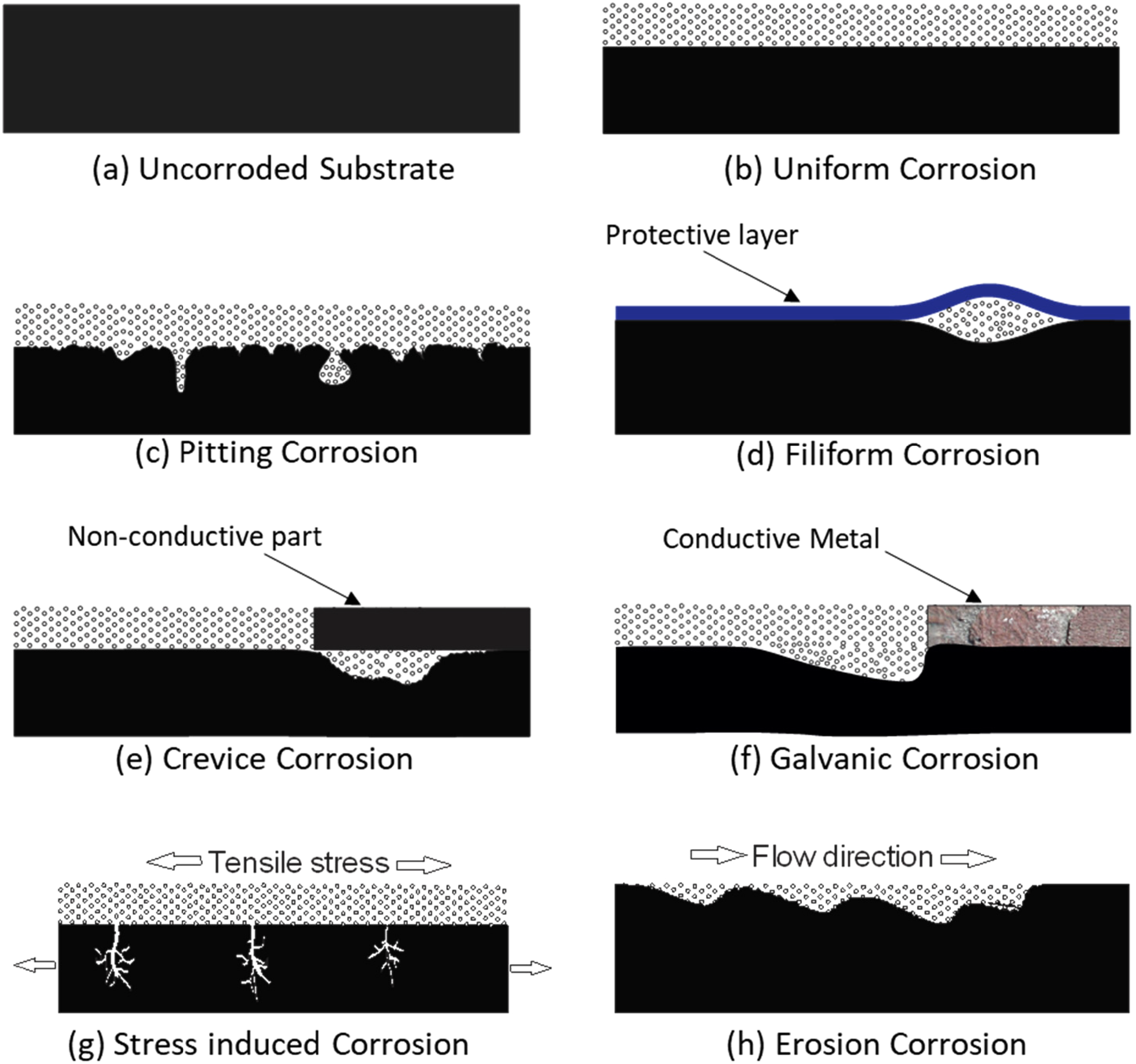
Localised corrosion has many forms of damage to the material, including pitting, crevice galvanic, filiform and intergranular corrosion. 13 All localised damage is electrochemical in nature. 7 The scope of this review is beyond focusing on these types of corrosion.
Corrosion monitoring and detection
Corrosion monitoring refers to the techniques used to assess the physical and chemical change in material to detect, measure and predict corrosion damage. In other words, these are defined as techniques used in acquiring data on the rate at which the material degrades.
Even though the terms corrosion monitoring and detection are used interchangeably, both are slightly different. Although both represent the process of inspecting the metal for any physical or chemical change, monitoring usually is a prognostic tool, while detection serves as a tool for maintaining the integrity of the equipment. 4
The following are the requirements for good corrosion detection systems:14,15
It should be able to detect the onset of corrosion in any location. It should have a rapid response. It should be reproducible and be accurate. It should be sensitive to detect and measure minor changes at early stages. Moreover, it should be cost-effective.
As mentioned earlier, corrosion monitoring techniques can be classified as non-destructive and destructive.
4
Corrosion coupons, electrical resistance, inductive resistance, electrochemical impedance spectroscopy, electrochemical frequency modulation and linear polarisation resistance are typical examples of destructive methods.
4
The non-destructive methods include visual inspection, ultrasonic and acoustic techniques, radiographic, electromagnetic, and guided wave (GW) techniques.
4
Both destructive and non-destructive methods are used to detect corrosion reliably and efficiently such that the substantial costs associated with the teardown inspections can be reduced.4,16
It's crucial to note that the field of non-destructive testing is dynamic, and new technologies may have emerged or existing ones advanced, which can be reflected with recent literature, and industry publications in the field. The current status of specific technologies or techniques with general overview of NDTs for corrosion monitoring and detection have been given here for the readers’ reference to explore the latest developments in each area through recent sources: Visual inspection remains a fundamental technique, and optical methods, including advanced cameras and imaging systems, continue to evolve for corrosion assessment. AE testing is commonly used for monitoring corrosion in structures. Advances in sensor technology and signal processing have improved the accuracy and sensitivity of this technique. Ultrasonic monitoring methods and ultrasonic testing is widely employed for corrosion detection. Advances in transducer technology and signal processing have enhanced the capabilities of ultrasonic methods. EC testing is effective for detecting corrosion in conductive materials. Ongoing developments focus on improving probe designs and data analysis techniques. GW testing is used for long-range inspection of pipelines and structures. Research is ongoing to optimise sensor configurations and improve data interpretation algorithms. Infrared thermography (IRT) is valuable for detecting surface temperature variations associated with corrosion. Continued advancements in thermal imaging technology contribute to its effectiveness. Radiographic NDT methods are well-established for sub-surface corrosion detection. Digital radiography and computed tomography are areas where ongoing research may lead to improvements. The techniques of microwave and millimeter-wave NDT are less common but are explored for their potential in detecting corrosion with ongoing research which may lead to more widespread applications. Terahertz imaging is an emerging technology with potential applications in corrosion detection with ongoing research to refine imaging capabilities and develop practical implementations.
The NDT refers to how the test specimen is evaluated without causing any damage. 4 These methods are used in quality control, in-service inspection without compromising the performance and to characterise the materials degradation rates over regular time intervals. 17 The data obtained from NDT is converted to parameters that can predict the components’ performance and life span. Since NDT methods are used in quality control for predicting defects, they increase safety and reliability and reduce labour and energy.
Visual and optical testing
Visual inspection is the most common corrosion monitoring technique that uses simple tools, including magnifying glass and flashlight, to perform the inspection. Visual testing can be classified as direct visual testing, remote visual testing and translucent visual testing. Direct visual testing is a traditional technique used to detect corrosion spots accessible to the inspector's naked eye within 600 mm with a visual angle not less than 30°. Mirrors are used to improve the angle, while a magnifying glass ranging between 2× to 10× is used to aid the inspectors’ evaluations. 18 Visual examination is one of the early tests practiced in the real world. They do this test before getting into sophisticated tests like ECs.
An optical device such as a borescope is available in remote visual testing to aid the naked eye inspection. 19 Several commercial borescopes are available with varying sizes introduced in openings as small as 3 mm or greater in diameter. Borescopes are thin, rigid optical devices that allow an inspector to view inaccessible areas by transmitting an image from one end to another. The magnifying aid ranges from 1.5× to 200× with a field of view typically from 90 to 0.15 mm. The resolution can range from 0.051 to 0.0002 mm. 20
Translucent visual testing uses backlighting on a translucent material to aid in detecting internal defects. The light sources used should be adjusted for their intensity that sufficiently diffuses within the component without any glare, which obscures the details of the component. 21
Recordings of these visual inspections are also available to ease corrosion monitoring. 22 The use of charge coupled devices (CCD) coupled with diffracto D-sight, 23 edge of light, 24 3D-optical profilometry, 25 Moire interferometry 26 and video imaging has been used recently to record the visual inspection. These recorded images can then be evaluated for surface defects, cracks or pitting.23,26
The main advantage of using this non-destructive visual inspection is the need for inexpensive equipment. However, these techniques are subjective and can be labour intensive if the examined area is large and mainly limited to open surfaces. 27 These qualitative techniques do not provide information on quantitative assessments of material loss and strength.
Moire interferometry and structured light are used to visualise and quantify surface height irregularities. The most common Moire technique in corrosion detection is the shadow Moire method, in which fringes of light are generated interferometrically, which uses a fringe shift algorithm to compute the surface contours. 26
Sentry holes are another form of visual inspection where a small blind hole is drilled on the wall of the equipment and monitored over a period for any leaks or defects. These sentry holes are carefully tailored to a specific depth across the wall of the equipment to facilitate temporary plugging until a convenient shutdown time. 28
Effectively speaking, visual inspection merits special attention that requires training on the knowledge of the component, the conditions to which the component is exposed, and other details that are needed for the inspector to look for specific types of defects. 23
Liquid penetrant
Liquid penetrant (LP) is a low-cost, portable and easy-to-use technique used to detect flaws on the component's surface since the 1800s, primarily in railroads maintenance.29,30 The liquid penetrant technique uses dye to enhance the flaws on the component. It can be used for ferrous and non-ferrous alloys and metallic and non-metallic materials. Liquid penetrants have either bright colours or fluorescent dyes, which efficiently penetrate and fill the cracks. 31 Usually, there are a series of steps involved in liquid penetrant testing. First, an excessive amount of dyed penetrant is applied on the affected surface, soaked for 20–30 min to let the penetrant seep through the cracks and cavities via capillary action. 32 After soaking, the excess liquid is removed, and a developer powder, usually an absorbent, is applied to the surface. This powder draws the penetrant absorbed out the cracks via reverse capillary action leaving a broader indication at the defect regions. The powder, called developer, spreads from the cracks is monitored under a bright visible light source or a fluorescent lamp for defects. 33 The steps involved in the liquid penetrant test are explained in Figure 2. 29
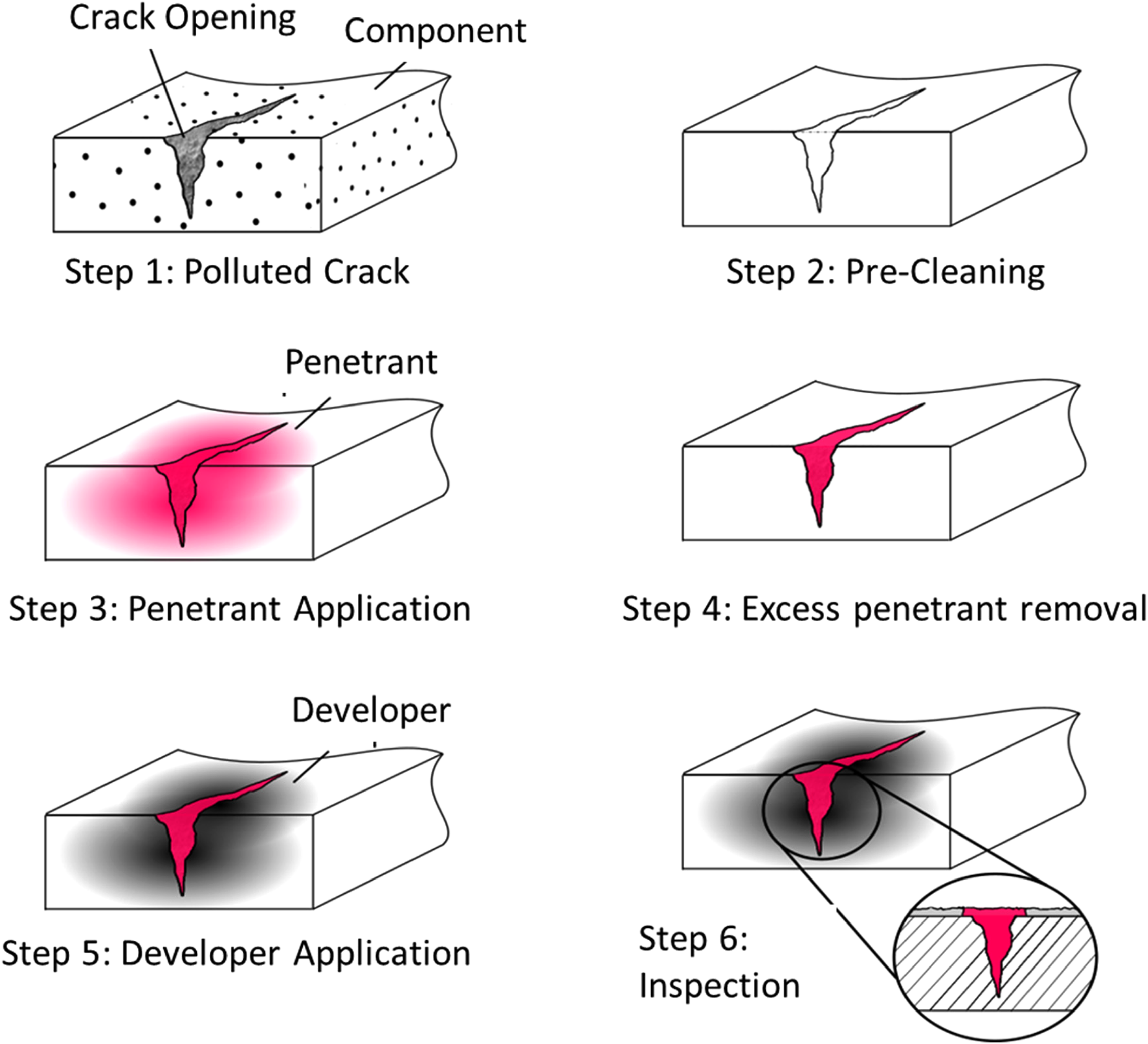
However, there are some limitations for using this technique: (i) it depends on the ability of the penetrant to enter and fill the discontinuity on the surface and (ii) it cannot be used over a porous or rough surface where the dye gets permanently trapped and which can mislead with the dye getting bleed into the open pores. 35 Also, (iii) the component's surface should be cleaned thoroughly such that the penetrant wets the surface completely. Finally, (iv) when the dye used is fluorescent and necessitates black or UV light for inspection, conducting on-line investigations using this technique becomes highly impractical. 36
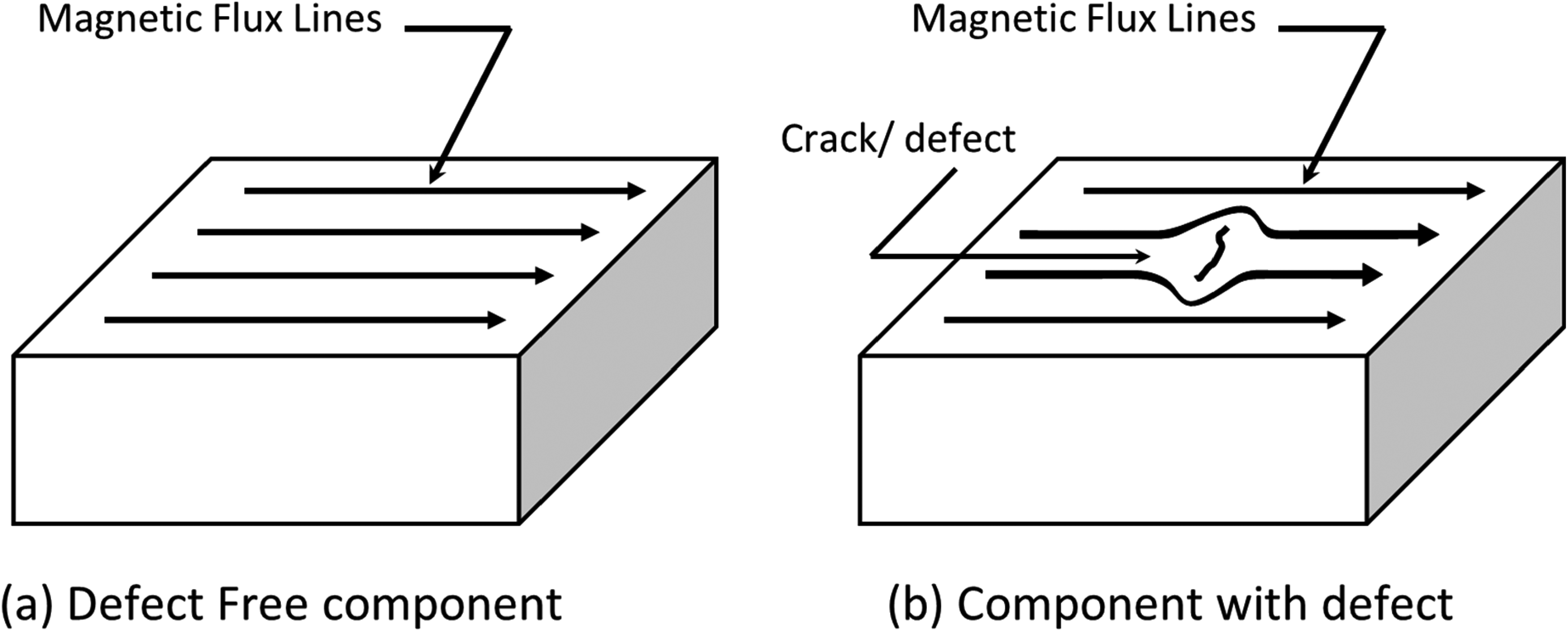
Magnetic particle inspection
Magnetic particle inspection (MPI) is a form of visual inspection similar to liquid penetration but uses magnetic particles to create a visual indication of the defect on the component. As the name suggests, MPI can be used only on magnetisable components. The principle of MPI is that magnetic lines of force are induced either by a magnet, electromagnet or an electric current that creates a magnetic field in the component. 37 The applied electric current can be either a direct current (DC) or an alternating current (AC). However, the use of DC increases the probability of detecting narrow cracks underneath the surface. 38 The magnetic flux is concentrated below the surface if the component is defect-free. However, flaws in the component interrupt these magnetic lines of force where it exits and re-enters, creating opposite magnetic poles. When the component is sprinkled with tiny magnetic particles, they concentrate on these magnetic perturbations.
Usually, the magnetic particles are suspended in water or paraffin, which enables the particles to flow over the component's surface. The magnetic particles can be coloured to enhance the contrast of the visual inspection.37,39 Commonly used particles include black iron, red and yellow iron oxides. Using a fluorescent dye coated on a magnetic particle has also been reported. 40
The magnetisation techniques depend on the component shape and size, which can be categorised into DC and magnetic flux flow techniques. 37 In the DC technique, the magnetic field is created by the flow of current through the component, whereas in the magnetic flux flow technique, the magnetic flux is induced in the component using a permanent magnet or by flowing current through a coil or a conductor. 41
MPI is often used to detect cracks at welded joints, stress corrosion cracking, hydrogen-induced cracks, fatigue cracks and creep cracks, which are surface phenomena. 42 MPI is a visual indicator that can approximate the size and shape of the surface or sub-surface defects. The surface does not have to be clean, unlike the liquid penetrant technique. MPI is an inexpensive, fast, and reliable technique that can be used on complex shapes to detect surface and sub-surface defects on ferromagnetic material (Figure 3).43,44
The main disadvantage is the need for the component to be ferromagnetic, and hence defects on aluminum, copper and austenitic stainless steel cannot be detected through MPI. 47 The orientation and strength of the magnetic field play an important role in defect detection. If the cracks run parallel to the magnetic field, it is more likely that the magnetic flux is not disturbed, and the magnetic particles may not be concentrated; thus, detection becomes impossible. Hence, rotational techniques where the magnetic field is applied at 360° of the sample are used. Some large industrial parts might require large currents, damaging the component itself. MPI technique, as mentioned earlier, can be used in detecting the surface and near-surface defects and cannot be used to detect embedded flaws.37,47
Diffracto sight
Diffracto sight (D-Sight), developed by Diffracto Ltd in Canada, is a surface slope visualisation technique, which uses a double-pass light reflection to measure the surface defects. 4 The concept of D-sight is based on the schlieren method, that light rays are bent when they encounter a change in density of the medium and are used in visualising the refraction gradients in the optical system. This is used to monitor the surface variations of a huge component. 23
Figure 4 shows the D-sight system. It consists of a light source, a retroreflective screen and a camera. The light rays are focused on the component to be tested for defects, which reflects it to the reflective screen, usually consisting of numerous half-circled silver beads with a diameter of 60 µm. 48 This reflective screen reflects all the incident light rays to the component, reflecting to the camera placed slightly off-set to the light source. 49 The surface distortions on the component cause the variation in intensities of the light reflected from the glass beads. Depending on the view angle and the slope of the surface, the reflected light intensity from the surface distortion will be higher on one side, creating a brighter image and a darker image on the other side. 48 This change in intensities from distorted samples is used to inspect the sample visually. A schematic setup of a D-sight tester is shown in Figure 4.
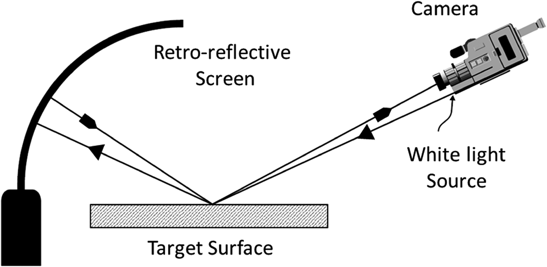
Principle of the D-sight non-destructive technique (redrawn based on reference 50).
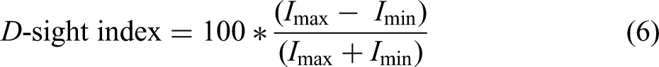
In addition to the image analysis, the intensity difference can quantify the defects by using the D-sight index, representing the contrast from the surface defects detected through the D-sight technique.
23
D-sight index can be calculated as below.
51
D-sight is a non-contact method that can identify surface waviness. The D-sight technique can be used to measure the damaged area larger than 5 cm2, with a field of view of about 0.25 m2 with a sensitivity of 0.01 to 0.05 mm of profiles. 51 It can even detect the surface waviness of the component accurately. Recent advances include using laser beams and computer-aided software to view and record these defects. 4
The D-sight technique can only be used when the component is spectrally reflective. A thin layer of water is used frequently to increase the surface reflectiveness. However, this technique can be labour intensive because of the need to focus the light rays at a certain angle to be reflected. 52
Edge of light
Edge of light (EOL) is another similar form of NDT using light waves where a rectangular beam of light is focused on the object's surface, and the reflected intensity is used to detect the slopes on the component, as shown in Figure 5(a). 53
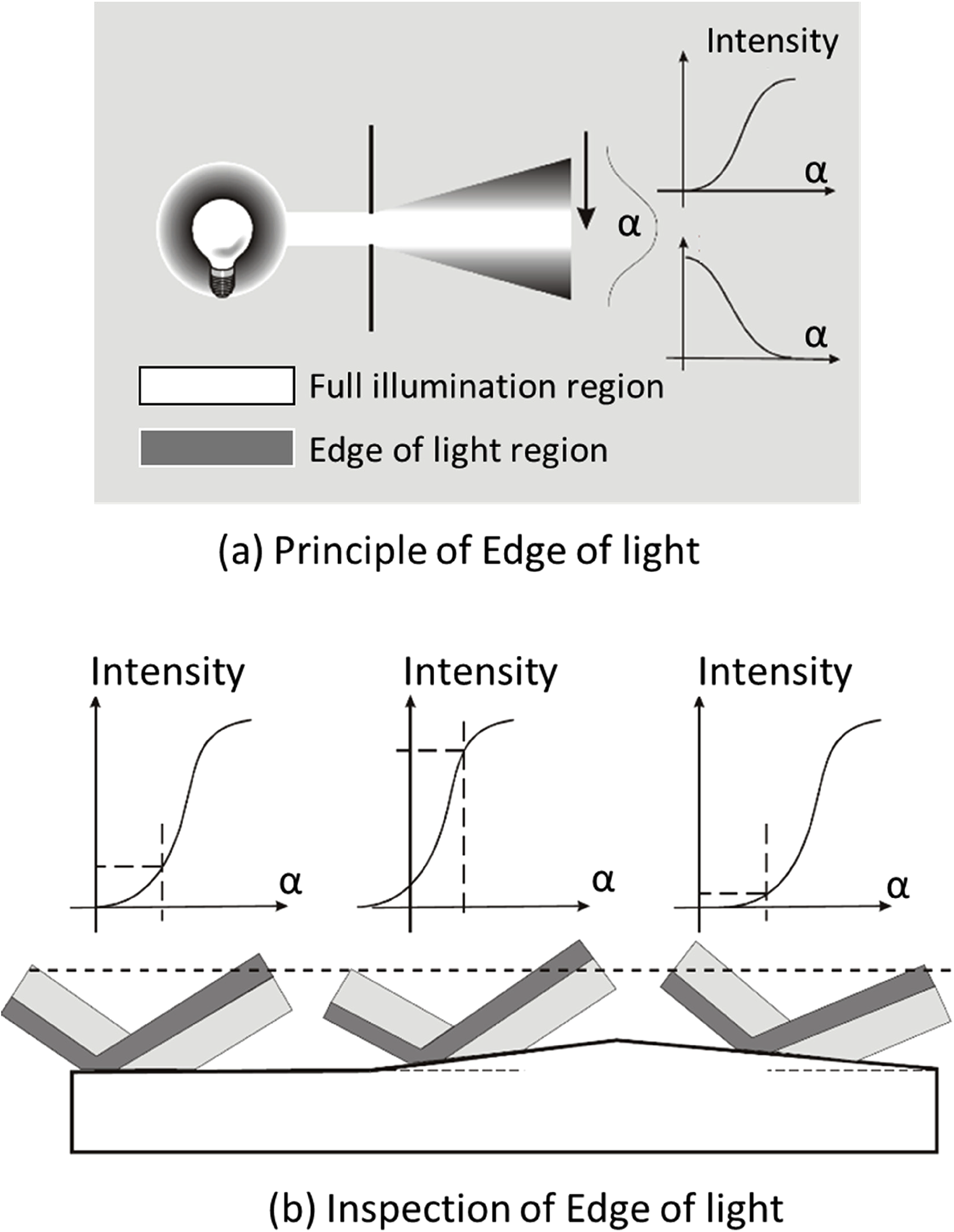
A rectangular band of light is generated from a light source placed behind a slit. This rectangular band of light has two regions, full illumination region on the centre (shown in white in the Figure 5(b)) and the edge of light region on both sides of the full immumination region (shown in grey in the Figure 5(b)). The brightness intensity in the full illumination is constant while the brightness intensity in the edge of light region changes rapidly. The EOL detector is tuned to receive reflected beam of light from the object under investigation which is operated in the middle of the EOL region in either increasing or decreasing brightness intensity as shown in the graph. The intensity of the reflected light is used to analyse the defect on the surface. The analysis can be either inspection surface reconstruction, where the refelected intensity value is derived for every pixel in the EOL image and principle component analysis in which each original image is represented by a llinear combination of eigen vectors.
The EOL monitors the reflected light from a light source using a detector held at a constant position placed in the opposite direction. 24 The variation in the light intensity is used to map the surface defects through image reconstruction with the aid of computer-aided devices.
The detector in EOL is set up to operate in the middle of the edge of the light zone. When the surface is smooth without any defects, the intensity remains constant, whereas, at the edge of a slope, the reflected rectangular beam of light shifts. 55 The intensity of the detector is held at a constant position because of this shift in the reflected light. Unlike the Diffracto-Sight technique, this can be used to monitor small surface defects with scanning speeds in the order of 2–20 linear cm s−1 with widths more than 10 cm or more. 56
The main disadvantage of EOL is that this method enhances the the surface deformation caused by flaws, which need not essentially araise due to the corrosion products alone. This technique involves manual error in measurements which might mislead the measurements made using EOL.
The traditional optical techniques, including borescopes, rely on the principles of light reflection and transmission, which may not be as effective when dealing with opaque materials like metals and plastics. The primary challenges with using optical techniques on opaque surfaces are the limited penetration of light and the difficulty in visualising structures beneath the surface.
For opaque materials, other NDT methods that don't rely on optical principles might be more suitable. Here are a few alternative techniques commonly used for inspecting opaque materials.
Ultrasonic testing (UT): Ultrasonic waves can penetrate opaque materials such as metals and plastics. By sending ultrasonic pulses into the material and measuring the time it takes for the echoes to return, it's possible to detect internal flaws, voids or thickness variations.
EC testing (ECT): ECT is effective for detecting surface and sub-surface defects in conductive materials. It's commonly used for inspecting metal components. ECT works by inducing electric currents in the material and measuring changes in the electromagnetic field caused by defects.
X-ray and radiographic testing: X-rays can penetrate opaque materials to reveal internal structures. Radiographic testing involves exposing the material to X-rays, and the resulting image can be used to identify defects, voids or inconsistencies.
Magnetic particle inspection (MPI): MPI is primarily used for ferrous materials. It involves applying a magnetic field and then applying magnetic particles to the surface. The particles will accumulate at locations with magnetic field irregularities, highlighting potential defects.
Dye penetrant testing (PT): Although more suitable for surface defects, dye penetrant testing can be used on opaque materials. It involves applying a coloured liquid to the surface, which penetrates into surface-breaking defects. After excess liquid is removed, the defects become visible under certain lighting conditions.
These techniques provide effective means of inspecting opaque materials, each with its own advantages and limitations. The choice of the appropriate method depends on factors such as the material being tested, the type of defects expected, and the specific requirements of the inspection.
Acoustic emissions
AE is a global monitoring technique based on detecting the acoustic waves in a material that undergoes microscopic defects such as corrosion or defect formation mainly used to detect stress corrosion cracking. 57 Essentially, this technique utilises a highly sensitive microphone as acoustic sensors, placed at multiple locations on the surface of the equipment, which can detect the acoustic signals produced from the materials’ stress.29,57,58 AE refers to the release of transient stress waves produced by the rapid release of energy from localised sources within a material. The level of AEs is typically categorised into low-level and high-level events based on the amplitude and energy associated with the emitted waves.
Low-level AEs: Low-level AEs generally refer to signals that are of relatively low amplitude and energy. These events are often associated with minor or early-stage damage, such as microcracking or the initiation of defects within a material. While these emissions may not be readily audible to the human ear, they can be detected and analysed using sensitive sensors and signal processing techniques. Low-level AEs are frequently used for monitoring the early stages of material degradation, making them valuable for preventive maintenance and structural health monitoring.
High-level AEs: High-level AEs correspond to signals with greater amplitude and energy, indicating more significant and often rapid release of energy within a material. These events are typically associated with the propagation of cracks, fracture or other forms of advanced damage. High-level AEs can be indicative of critical structural issues or imminent failure. Monitoring and analysing high-level AEs are crucial for identifying and assessing the severity of damage in materials and structures, enabling timely intervention and maintenance to prevent catastrophic failure.
In practical applications, the distinction between low-level and high-level AEs depends on the specific context, material properties and the monitoring system's sensitivity. AE testing is widely employed in various industries, including structural health monitoring of civil infrastructure, aerospace and manufacturing, where it serves as a valuable non-destructive testing method for detecting and characterising material damage and degradation.There are two types of AE from a material, a low-level and a high-level. A low-level AEs are generated from plastic deformation, microstructural changes or a slow corrosion chemical reaction. These low-level AEs generally pose less catastrophic failures, while the high-AE detected from a sudden burst of energy, arising from a discrete flaw like cracks, the burst of bubbles and cavitation, can be disastrous. 58
A typical AE device utilises a piezoelectric sensor that translates acoustic signals to an electrical signal that is then amplified, filtered, and viewed as images. This imaging technique is used as a quality control tool on a large area, both on-line and off-line inspections. 30 For an off-line inspection, a frequency range of 150 to 175 kHz is used for wide coverage, while on-line flaw investigation techniques can use up to 1 MHz. 59 Most commonly, AE is used for on-line inspection where the material is at constant stress. A flaw is flagged when there is a change in the AEs background noise level. Since this is an on-line technique, it can take months or even years to detect the flaws. 60 The off-line inspection involves testing material for flaws when subjected to external pressure or temperatures that typically last for a shorter period.58,59
The type of AE generated is the property of the material in use. Depending on the type of stress and the failure rate, the AE events can be either primary or secondary. 61 For instance, primary AE on a stainless steel material is through falling-off of grain because of the combined actions of anodic dissolution and mechanical fracture happening at the grain boundary of chromium-depleted zone. At the same time, the secondary AE was generated via hydrogen gas evolution from the corrosion process. 44
AE signals are only used in corrosion detection when the material undergoes stress. Pollack extensively summarised the corrosion process that can be detected using AE. 62 Defects based on the passage of electric current, dissolution of metal, and passive film formation, which do not create lattice stresses, are non-detectable using AE NDT. Other corrosion processes such as microcracking and gas evolution that induce stress fatigues are detectable via AE methods. 62
AE technique has been used to detect surface corrosion when there is induced stress due to the breaking of corrosive films through erosion, chemical reaction or the evolution of hydrogen gas. Several studies on detecting surface corrosion have been reported where a local area of the defective material is subjected to heat while AE was recorded.63–67 A corroded surface when compared to an uncorroded material under heat, the AE signals increased 15 times as compared to the uncorroded material. This implies that the AE signals are due to the stress-induced during the breakage of the corrosion film because of thermal expansion. 63 AE has been used in detecting pitting corrosion, cracking and material degradations. AE from pitting corrosion is formed from the stress developed in scale-up and oxide layer formation and cracking. 68
The advantage of this technique is that the AE signals are produced inherently from the flaw growth in the material, eliminating the need for a source and a receiver as in traditional NDT. 69 Since the AE signals are associated with the inherent materials property, and the service environments usually create background noise, appropriate noise reduction and signal discrimination are extremely important before evaluating any defects. The main disadvantage includes the lack of detection of passive defects, and these methods are highly prone to false indications from scattered wave motions. 17 AE systems information is usually qualitative, which estimates the materials’ life duration while missing the quantitative details. Thus, additional NDE must be performed for understanding and evaluating the corrosion process. 70
While it's true that AE monitoring, like any other non-destructive testing method, has limitations, it also offers unique advantages in certain scenarios.
Early detection capability: AE monitoring is known for its ability to detect incipient damage and early-stage flaws that might not be visible through other inspection methods. By identifying these early signals of degradation, it provides an opportunity for proactive maintenance and intervention before the damage progresses to a critical state.
Continuous monitoring: AE can be implemented for continuous, real-time monitoring of machinery, allowing for the detection of dynamic changes and the onset of damage during normal operational conditions. This continuous monitoring aspect can provide insights into the evolving condition of the equipment.
Complementary technique: While AE is valuable for certain types of damage, it is often used in conjunction with other non-destructive testing methods to provide a comprehensive assessment of machinery health. Combining multiple techniques enhances the likelihood of detecting various types of flaws and ensuring a more thorough evaluation.
Risk assessment and mitigation: Understanding the limitations of any monitoring technique is essential. For critical machinery, a risk-based approach can be adopted, where the combination of AE and other methods helps in assessing the risk of failure and implementing appropriate mitigation strategies.
Implementation considerations: Successful implementation of AE for on-line monitoring requires proper sensor placement, system calibration and continuous data analysis. With careful consideration of these factors, the effectiveness of AE in providing early warnings can be optimised.
While AE may not be a standalone solution for all monitoring needs, its capabilities in early flaw detection and continuous monitoring make it a valuable tool when integrated into a comprehensive predictive maintenance programme. The key lies in understanding its strengths and limitations and using it in conjunction with other techniques to ensure a well-rounded approach to machinery health monitoring.
AE monitoring is generally not a direct method for establishing intergranular corrosion. AE is more commonly used for detecting and monitoring the acoustic signals produced by the rapid release of energy from localised sources within a material, which can be associated with various types of damage, including cracking, fatigue and some forms of corrosion.
Intergranular corrosion, on the other hand, is a specific type of corrosion that occurs along the grain boundaries of a material. Establishing or assessing intergranular corrosion typically involves techniques more specific to corrosion testing, such as metallography, microscopic examination or electrochemical methods. For detecting or assessing intergranular corrosion, traditional corrosion testing methods like metallography, corrosion coupons, electrochemical tests or specialised corrosion monitoring techniques would be more appropriate. These methods provide insights into the corrosion behaviour at the grain boundaries of a material. It's crucial to choose the right technique based on the specific type of corrosion, the material in question and the conditions it is exposed to.
Stress corrosion cracking (SCC) is a specific type of corrosion-related damage that occurs under the simultaneous influence of tensile stress and a corrosive environment. SCC is characterised by cracking of a material, often along grain boundaries, due to the combined effects of stress and corrosion. AE monitoring can be applied to detect and monitor the occurrence of stress corrosion cracking. The process involves the release of transient stress waves generated by the rapid development of cracks within the material. AE can be used for SCC in different ways.
Early detection: AE is sensitive to the initiation and propagation of cracks. In the context of SCC, AE monitoring can provide early detection of crack formation before they become visually apparent or lead to catastrophic failure.
Real-time monitoring: AE can be employed for continuous, real-time monitoring of structures and components susceptible to stress corrosion cracking. The technique allows for the identification of dynamic changes in the material condition during service.
Localised detection: AE sensors can be strategically placed to monitor specific areas where stress corrosion cracking is likely to occur. This targeted approach enhances the ability to detect and locate the development of cracks in critical locations.
Failure prediction: The monitoring of AEs can provide valuable data for predicting the progression of stress corrosion cracking, enabling timely intervention and preventive maintenance to avoid unexpected failures.
While AE can be a useful tool in detecting stress corrosion cracking, it is often used in conjunction with other inspection methods, such as visual inspection, ultrasonic testing and electrochemical techniques, to provide a more comprehensive assessment of material integrity. Additionally, the successful implementation of AE for SCC monitoring requires careful consideration of factors such as stress levels, environmental conditions and the material's susceptibility to stress corrosion.
The penetration depth of acoustic waves into a metal surface is influenced by the frequency (energy) of the waves. In general, higher-frequency waves have shorter wavelengths and, therefore, lower penetration depths, while lower-frequency waves have longer wavelengths and can penetrate deeper into the material. Here are some general trends regarding penetration depth and frequency for different types of acoustic waves.
Ultrasonic waves: Ultrasonic waves have frequencies typically in the range of 20 kHz to several megahertz. The penetration depth of ultrasonic waves into metals is generally limited to a few millimetres to centimetres, depending on the frequency and the material's properties. Higher-frequency ultrasonic waves are used for surface inspection, while lower-frequency waves can be employed for sub-surface inspection.
Guided waves: GWs, such as Lamb waves, are lower frequency acoustic waves that can travel along the surface or through the thickness of a material. The penetration depth of GWs is influenced by the frequency, mode of propagation and material properties. These waves are often used for inspecting structures like pipes and plates.
Rayleigh waves: Rayleigh waves, which are surface acoustic waves, have a penetration depth that is typically on the order of one wavelength. Their penetration depth is influenced by the frequency, and they are often used for surface inspection.
Shear waves and longitudinal waves: In ultrasonic testing, shear waves and longitudinal waves are commonly used. Shear waves typically have lower penetration depths compared to longitudinal waves. The penetration depth increases with the wavelength, which is inversely proportional to the frequency.
It's important to note that the specific properties of the metal being tested, such as its density, elastic modulus, and the presence of any coatings or surface treatments, can also affect the penetration depth. Additionally, the choice of frequency depends on the inspection requirements and the type of defects or features being targeted. Higher frequencies are often used for detecting smaller defects near the surface, while lower frequencies are employed for deeper inspections.
In summary, AE is a cost-effective and sensitive technique. The main mechanism responsible for AE waves is the stress created in a material when pitting and crack initiation and propagation occur during the corrosion process. However, several researchers61,70 reported hydrogen gas generation at the anode, detachments of corrosion products from the surface, and the cathodic reactions can also create the AE waves. With the advanced sensitivity, computer-based processing algorithms can be utilised to locate early stages of corrosion on a larger evaluating area.
Ultrasonic monitoring methods
Ultrasonic inspection (UI) uses a transducer containing a piezoelectric crystal to send a high-frequency, ranging from 0.1 to 25 MHz, sound pulse through the component investigated, as shown in Figure 6. The pulse travels through the component until it reflects from a discontinuity or a back surface. 71 By examining reflected or scattered ultrasonic waves, it is possible to examine crack, pit, grain boundaries or any voids. The flaw size and location can be identified using the amplitude and arrival time of the reflected waves. 72
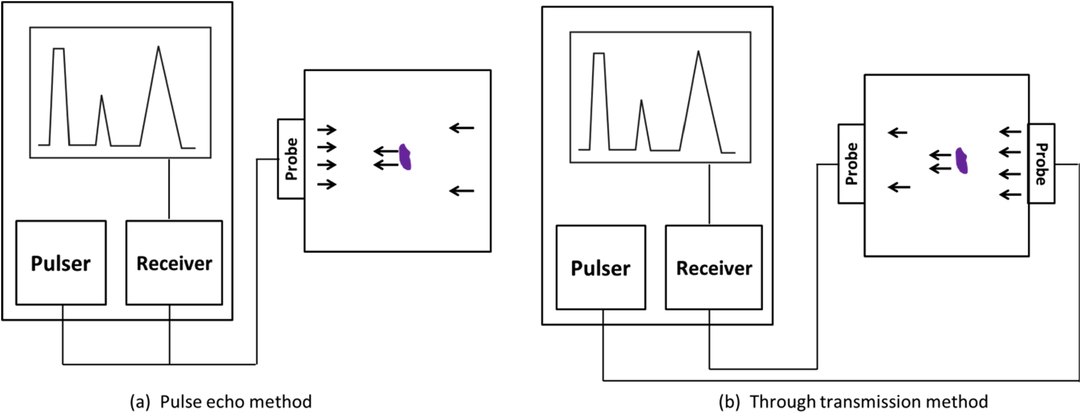
Principle of ultrasonic testing using pulse-echo method (a) and through transmission method (b) (adapted from reference 21).
The velocity of ultrasonic waves through a material is a function of the density and modulus of the material, making this technique useful to characterise the material. Materials microstructure can alter ultrasonic waves’ velocity, attenuation and backscatter. 73
The reflected and scattered ultrasonic waves are translated into time or frequency domains where an image is constructed to analyse any abnormalities in the sample. 74 Ultrasonic mapping can provide quantitative information on the type and orientation of the defects. Surface corrosion, pitting corrosion, erosion-based corrosion, cracking and material degradation have been investigated using this technique.4,17,73,75,76
Depending on the desired type of investigation required, ultrasonic waves are employed. The most common type of wave used is the longitudinal wave, where the beam enters the surface at 90°. 77 These waves travel through the component as a series of alternate compression and dilations such that the vibrations of the particles are parallel to the direction of the wave travel. These waves are used in detecting defects that are present in a reasonably large area parallel to the surface from which the test is made. However, detection of defects perpendicular to the surface is not effective. 78
Shear waves are commonly used in the ultrasonic inspection generated when the beam enters the surface at moderate angles. Unlike longitudinal waves, these waves can detect defects perpendicular to the direction of propagation. 79 However, shear waves have a velocity of 50% of the velocity of the longitudinal waves. However, shear waves have a shorter wavelength than longitudinal waves, making them more sensitive to small inclusions.72,80
Surface waves, also called Rayleigh waves, in ultrasonic testing, occur when the beam enters at a shallow angle. 73 These waves travel with little attenuation in the direction of the propagation. However, these waves are affected by variations in the component's hardness, causing their energy to decrease rapidly after the wave penetrates below the surface. 81
Lamb waves are a kind of waves that occur when ultrasonic vibrations are introduced at an angle, usually into relatively then sheets. These waves consist of a complex vibration that occurs throughout the thickness of the component. 82 The propagation of Lamb waves depends on the component density, lattice structure, elasticity, and vibration frequency. Typically, Lamb waves can be either symmetrical or asymmetrical. These can be further sub-divided based on the velocities controlled by the angle at which the waves enter the component. 83
An ultrasonic gage can be used to determine the thickness by measuring the travel time of the ultrasonic waves through the component's material and returning to the transducer.79,81,82 Through periodic measurements of the speed of sound through the material, the surface corrosion can be determined. Longitudinal mode thickness measurement ultrasonic transducer has been employed to monitor the wall thickness over time to characterie the material change. 78 Hagmaier reported a simple ultrasonic pulse-echo method to detect cracks through exfoliation. 84
Detection of hidden defects, that is, pitting corrosion and microcracking, is possible using ultrasonic testing. An immersion-type transducer with bubblers is used to decrease the ultrasonic scatters from the bulk defects to enhance the reflected signal. 72 These ultrasonic waves are scattered at the corrosion spots indicating the defects, while the reflected signals refer to the unaffected areas. 85 Usually, water is used as the immersion medium, making this technique difficult for on-line corrosion monitoring on a rougher surface. Recent advances include a dripless bubbler, a pneumatically powered device to hold a water column between the microscope and component surface. 86 An emerging interest also developed in laser ultrasound, where the sound waves are generated using a laser source. Laser ultrasonic testing is widely used in thickness measurement, weld, joint inspection and surface and bulk defect detection. 85
Studies by Splitt et al. 86 reported using a dual transducer where the ultrasonic waves were transmitted and received using two transducers sandwiching the specimen that was examined. A semi-automatic conversion probe was developed to evaluate corrosion on a generator tube on top of the naval boilers. 87 Ribichini et al. 88 and Fortunko et al. 89 determined the microcracks in bulk by employing electromagnetic acoustic transducers (EMAT) using Lamb waves. Their work demonstrated non-contact methods to detect the defects allowing high-speed and high-temperature applications.88,89 Grain size measurements were carried out by Goebbels using backscatter measurements. 90 While the backscatter technique can measure both microcracks and inclusions, it was difficult to differentiate between these two. 88
The advantage of using the ultrasonic method is that the measurements may be taken from the outside wall, allowing an on-line inspection due to its high penetrating power. 80 These techniques can be employed to measure the pit depths by using the arrival time of the reflected signals that were focused through the front surface. Any hidden profile of the component can be determined using this technique. 81
The disadvantage of using ultrasonic measurements degrades rapidly with increased surface roughness. Thus, when one of the two surfaces is corroded, the transducers are placed on the smoother surface for better resolution.81–83,85 These methods cannot be applied when pitting occurs in the bulk of the material vertically underneath surface defects. 71 This is because the ultrasonic waves are attenuated at the surface defects before reaching their bulk, making this approach ineffective. The main limitation of the immersion method is the maximum operating temperature of approximately 94°C, beyond which the sensitivity was limited. 91
Ultrasonic techniques were initially used to measure the thickness of the material and the size of the defects. There have been a lot of recent advancements,72,74,77,80 such as point-by-point measurements, time of flight diffraction (TOFD), EMAT, and phased array technology to enhance the resolution and sensitivity of this technique.
Eddy current
The EC testing principle, summarised in Figure 7, is similar to electromagnetic induction. EC technique uses a continuous signal to measure the characteristics and conditions of the material. 92 EC is generated when an electrically conductive material is subjected to an alternate current generated through a coil, which creates a varying magnetic field on both the surface and below the object's surface. These generated ECs, in turn, generate their magnetic field that opposes the coil's magnetic field, creating impedance (resistance of current flow). The magnitude and phase of the impedance are monitored to detect the integrity and size of the defect.93,94
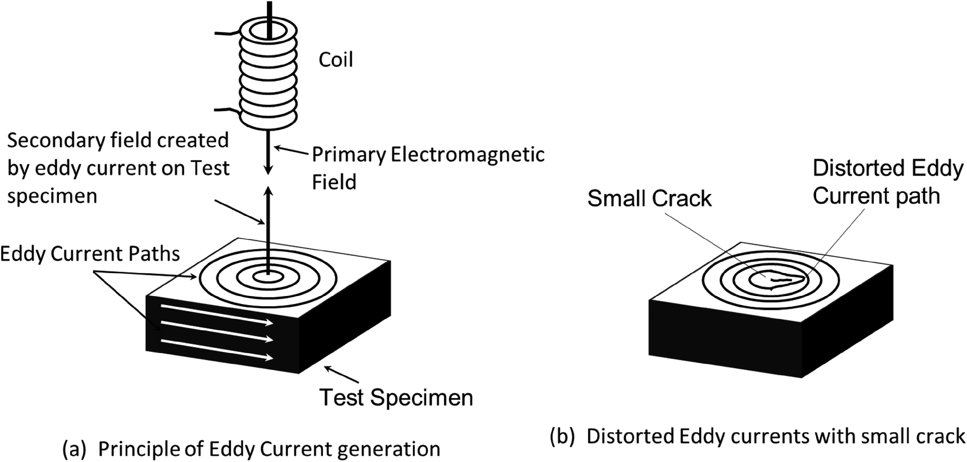
Principle of Eddy current generation on an unaffected and affected component shown in (a) and (b) respectively (adapted from reference 21).
The diffusion of these EC is the characteristics of the material on magnetic permeability, the wall thickness of the material, conductivity of the specimen and the frequency of the alternating probing signal.
93
Usually, surface detection can be accomplished by using coils as small as 3 mm in diameter that operate at a high frequency of 100 kHz and above. The penetration depth can be increased to sub-surface regions by using low-frequency ECs (LFEC), usually ranging from 100 to 50 Hz.
95
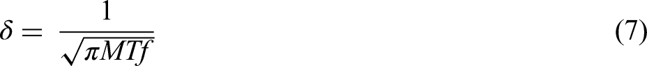
The standard depth of penetration (δ) is defined as the distance below the surface of a flat specimen at which there is 37% EC charge density on surface. The standard depth of penetration is inversely dependent on magnetic permeability (M), electrical conductivity (T) and the frequency generated by the coil (f) and can be expressed as in the below equation,
31
There are three types of probes available in EC methods, that is, internal probes, encircling probes and surface probes. A schematic representation of these kinds of probes is shown in Figure 8. 31 Internal probes are mainly utilised as an on-line in-service inspection to measure the corrosion performance of the component over the inspected period. Typical examples include machinery in refineries where the performance of the components is constantly monitored. 97
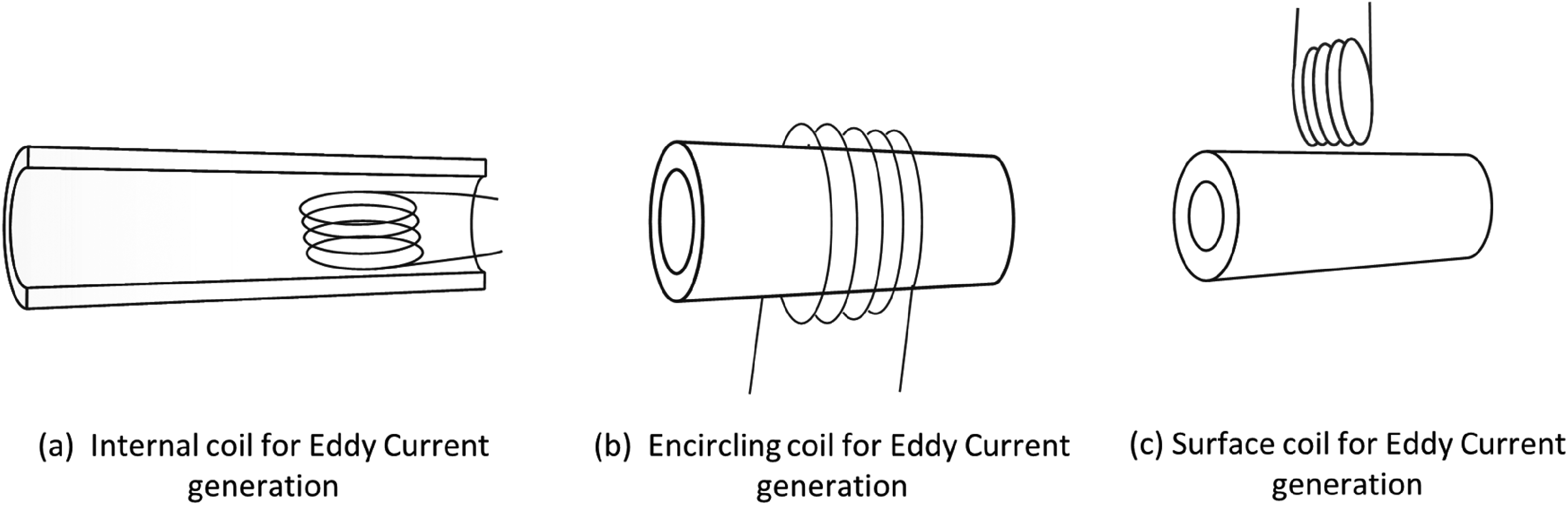
Different types of probes used to generate Eddy current (adapted from reference 21).
Encircling probes are typically used in testing pipelines and tubes during manufacture. These probes are mainly used in quality control setups. Surface probes are another kind of probe used as handheld devices that can measure the defects irrespective of the shape of the component. 98
There are different forms of EC methods used in inspecting components for corrosion. As mentioned earlier, LFEC are used to determine the defects in the underlying structure. 95 Remote-field EC (RFEC) was developed widely to inspect defects on pipes and tubing. 99
RFEC consists of two coils offset by two pipe diameters, usually operating at a minimal frequency such that the electromagnetic field is transmitted through the entire pipe thickness. 100 The transmitted electromagnetic field creates ECs that radially diffuse to the outer wall and spread on the exterior with little attenuation. This field diffuses back to the inner wall boundary while the field interacts with the defects in the tube.99,101 The main advantage of RFEC is its through-wall technique, which gives access to inspect the defects across the entire wall cross-section compared to traditional EC, which can be limited to the surface and sub-surface defects. 102 However, RFEC is limited to detecting pits due to the interference of corrosion products to these signals. 35
Pulsed EC (PEC) is another form of EC where the penetration depth is higher, relatively insensitive to the lift-off, which provides quantitative information on the wall thickness with <5% accuracy. 103 It employs analysis of the peak amplitude and zero crossovers of the response to the input pulse to characterise the material. The advantage of this technique is that the wall thickness can be in the range of 6 to 65 mm and the insulation thickness of <150 mm.92,99 The other significant advantage of this instrument is that it can reliably measure the material loss in a multilayered system, including the material loss on the bottom of the top layer, the bottom of the bottom layer, and the top layer of the bottom layer.94,96,97
Recent advances in EC imaging techniques involve using a magneto-optic imaging system (MOI), where simultaneous EC excitations from two orthogonal directions are made to gain better penetration through the component.104,105 MOI is based on the principles of Faraday magnetic rotation, where two-dimensional images are created by combining electromagnetic and optical energies. The response of the Faraday magneto-optic sensor to weak magnetic fields generated by EC to a defect in the inspected component is used to create an image.105,106 This technique is fast and reliable with relative insensitivity to the lift-off. Data interpretation is relatively simple since this is an imaging technique with a low signal-to-noise ratio. 105
EC monitoring techniques play an essential role in NDT where the surface is rough or inaccessible. Thus, the sample preparation step is not required to perform the EC testing, which adds to the advantage of being fast, thereby reducing the cost of corrosion detection. 107 This method is used to detect surface defects, measure thin walls from one side only, and measure the depth of the defects. The EC technique is used to detect minimal defects < 100 µm with an accuracy of <±5% of the wall thickness has been reported. 108 Since this technique, unlike ultrasonic testing, does not require a couplant, this technique can be used as an on-line monitoring tool and an off-line quality control tool. The EC provides spontaneous response accompanied by high scanning speeds.103,106,107 The pulsed EC technique uses a stepped or pulse input signal, requiring a larger penetration depth and thick wall penetration. Recent advances include automated scanning of multiple probes that generates a quick inspection of the components. Most modern EC testers are hand-held devices.92–94
ECs are sensitive to the electrical conductivity, magnetic permeability, geometry of the component and defects. This method applies only to electrically conductive materials. Though the EC arrays are flexible, precise location is crucial to accurate measurements. 99 However, pulsed EC has been employed to detect inaccessible corrosion. The other limitation these techniques have is their operating temperatures. These techniques can be used on surface or sub-surface defects closer to the surfaces.101–103
Guided waves and equipment
GW refers to the mechanical waves in an ultrasonic frequency to propagate through a component to which it is attached. This is termed a GW because the waves are aided to travel parallel to the boundary of the medium. In contrast to ultrasonic waves that travel at constant velocity through the medium, the velocity of GWs significantly depends on the frequency used and the geometry of the medium. 109 Depending on the component's geometry, the propagated waves can exist in different forms; in pipes, they can exist in three different modes namely longitudinal, torsional and flexural, while in a flat plate, they can exist as longitudinal horizontal modes. More details on these GW mode types can be found elsewhere.110–113 With the proper selection of wave mode and frequency, it is possible to investigate a larger area without scanning the entire surface for defects.
Depending on the frequency of the GWs, the detection range can be tuned. For short-range detection, a high-frequency wave that uses a Rayleigh wave is used to detect defects less than a metre.111,114 For medium-range testing, the typical use of frequency ranges from 250 kHz to 1 MHZ is used to detect defects up to 5m range is reported.112,115,116 In the case of long-range testing, with a frequency below 100 kHz, it is possible to measure up to 150m flaw detection. This long-range is of particular interest to several areas of corrosion detection because of its ability to scan a large area with a single fixed transducer compared to conventional ultrasonic or EC methods, which require scanning over the entire area.117,118
GWs can be generated using piezoelectric transducers, capacitive transducers containing ferromagnetic materials and lasers. Guided Wave Ultrasonic Limited developed the technique for investigating the defects through the pipes using piezoelectric transducers. 112 These transducers can only be used in cylindrical geometric components. The transducer that uses a ferromagnetic device to generate GWs is called magnetostrictive sensor technology. Usually, the ferromagnetic strip of 0.15 mm has a high magnetostrictive property attached to the component. This component can be of any geometry, including pipes, plates and irregular shapes.110,119 The piezoelectric transducers can detect defects from 5% to 10% of the cross-section of the pipes, whereas the ferromagnetic strip-based transducers can be used in orders of 3% to 5% of the component cross-section.110,113 The ferromagnetic type transducers being attached to the components are used to detect the component's behaviour at various times to monitor the changes in the component characteristics.112,120,121 The operating temperature limits for piezoelectric transducers can be in the range from 70°C to 120°C, whereas while using ferromagnetic strip transducers can be from −150°C to 300°C. 120
Nickel has been proven to be a successful ferromagnetic strip that can be attached to the component of inspection. 49 This is used in torsional mode to transmit the waves within the component because of its advantages such as non-dispersive which eliminates the dispersive effects, a better signal-to-noise ratio can be obtained, and the data received with the torsional mode is easy to analyse.120,122 Despite its advantage, torsional mode requires direct contact with the tested component which can be challenging if the component is coated or insulted. These ferromagnetic strips are either welded or glued strategically to the component and can be used to detect flaws over a large area of the component.109,112
The third method uses ultrasonic laser methods where the GWs are generated using a pulsed laser source. This has the advantage of being a reproducible ultrasonic source, defining the reproducibility zero time to better than 5ns enabling time measurements. 123 These laser-GWs are a non-contact method and can be used at elevated temperatures. The main drawback of these laser-induced GW techniques is the requirement of the surface like a mirror. 124 Hence extensive sample preparation is required before using a laser as the source to generate the GW.
The main advantage of the GW technique, as mentioned earlier, the GWs can be excited at one location and will propagate many metres. Reports show that the GWs can travel as far as 150 m from one source, and defects such as corrosion, welding, or any change in cross-section are detectable over the entire investigated volume.112,113
The drawback of this technique is that the GWs do not provide a piece of quantitative information on the flaw making this technique to be used as a screening tool. 125
Infrared thermography
Thermography is the study of a component's surface temperature response while exposed to heat. IRT is an imaging technique that detects the thermal radiation differences over a range of infrared spectrums when heated. 126 The principle of using IRT in a non-destructive method to monitor corrosion is to monitor the change in thermal radiation of the component whose thermal radiation at the affected area is higher. These defects include wall thinning, erosion or cracks. 127 This technique is mainly used in the inspection of pipelines used in petroleum refineries which involves high-temperature and high-pressure, although reports indicate the use of passive thermography to measure defects at temperatures slightly above ambient temperatures.128,129
Passive thermography, pulsed thermography (PT), and active lock-in thermography have been used recently to diagnose the components’ defects. Passive thermography is a qualitative test that measures temperature differences under normal conditions. This can be used in the early detection of defects in large structures. 130
PT is a non-contact method performed on a component at elevated temperatures. The thermal images are monitored during heating and cooling transient phases. 131 Lock-in (LT) and PT are other interesting thermographic techniques. In LT, the temperature is stimulated on the component either by using a heating lamp called the optical LT or by using an elastic wave called ultrasound LT. Detailed reports on these techniques can be found elsewhere.132–135
A new version of the thermographic method is the dual-band infrared computed tomography (DBIR-CT), where the inspected component is excited with a thermal pulse using a heat lamp. This DBIR-CT is equipped with two detectors in the 3–5 and 8–12 µm range to obtain results. With the DBIR-CT technique, a 3D image can be constructed with accurate depth information on the defects.129,130
Most IRT techniques are used as an area-type technique used to identify areas that should be inspected more carefully using more precise techniques. This is because of the lack of detailed insight the IRT provides on the defect present deeply in the component. 136 This can be overcome with thermal wave imaging (TWI) which measures the time response of a thermal pulse rather than a temperature response. The thermal pulse is capable of penetrating multiple layers provided the multiple layers are in contact with each other. 136 TWI can be used on a variety of materials including aluminum, plastics and steel. However, highly insulating materials such as rubber or glass can be a challenge.129,133,136
Usually, an infrared camera is attached to a mechanical stage to scan the component. The detecting wavelength can vary from 3 to 5.4 µm in an operating temperature range from −40°C to 950°C. 137 The thermal gradient is the property of the material, and it can significantly influence thermal conductivity. The lower the thermal conductivity, the higher the sensitivity of IRT. Thickness is also a critical factor in the sensitivity of this technique, where thinner components are shown better sensitivity.134,138
Other key factors that affect the IRT images include emissivity, atmospheric particles, ambient temperature and the distance from the component. Non-metallic surfaces with high emissivity are detected in IRT, whereas the metallic surfaces act as reflectors. This can be avoided by coating a metallic surface with a high emissive black coating.139,140 The presence of atmospheric particles on the view of IR waves can attenuate the signals through scattering or absorbing energy reflected from the component to the IR thermal imager. The distance from the component also impacts the resolution of the IR image. At a more considerable distance, the details of the defects are lost due to the averaging of the temperatures within pixels. 141
McKnight et al. reported the use of IT to evaluate the performance of a coating on a steel substrate. IT was used to characterise localised corrosion, voids underneath the coating, which appeared hotter than the surrounding area. 142
The main advantage of IRT includes the absence of any harmful radiation along with rapid full-field imaging. This technique offers a rapid, non-contact method for isolating a quantifying surface defect.139,143 In addition to surface defects, interfacial corrosion and estimating coating thickness in a non-contact manner makes this technique attractive. Under the average thermal gradient of the sample, these techniques can detect tiny defects with large scan areas with high throughput. 144
The limitation includes measuring the surface temperature rather than the bulk of the component. Defects that are deeply contained in the structure produce more blurred images than the defects of the surface. 145 The other disadvantage of IRT is the poor imaging obtained from a metal substrate having high thermal conductivity.138,141,143–146 However, Shen et al. 138 demonstrated the use of IRT techniques in detecting the loss of walls on different types of stainless steel and carbon steel. In cases where the components are at thermal equilibrium, this technique may not be the best choice. The use of IT on a layered structure can cause problems in precision and reliability. The enormous cost associated with the quality thermal cameras is one of the main drawbacks of commercialising this technique.147,148
Radiographic NDT
The radiographic NDT method is an imaging technique that can detect pitting, localised corrosion, and loss of wall thickness. Radiographic inspection utilises electromagnetic waves created using the X-ray, gamma radiation or any high-power energy rays of a very short wavelength that can penetrate the component. 4 This wave penetration depends on the density and the thickness of the component and the wave's frequency while the penetration power depends upon energy of the radiation. The transmitted wave absorption is utilised to detect the variation in the component, which is then recorded on a film or a digital electronic device to create a 2D image of the defect. 149 Figure 9 is a schematic representation that summarises the principles of this technique.
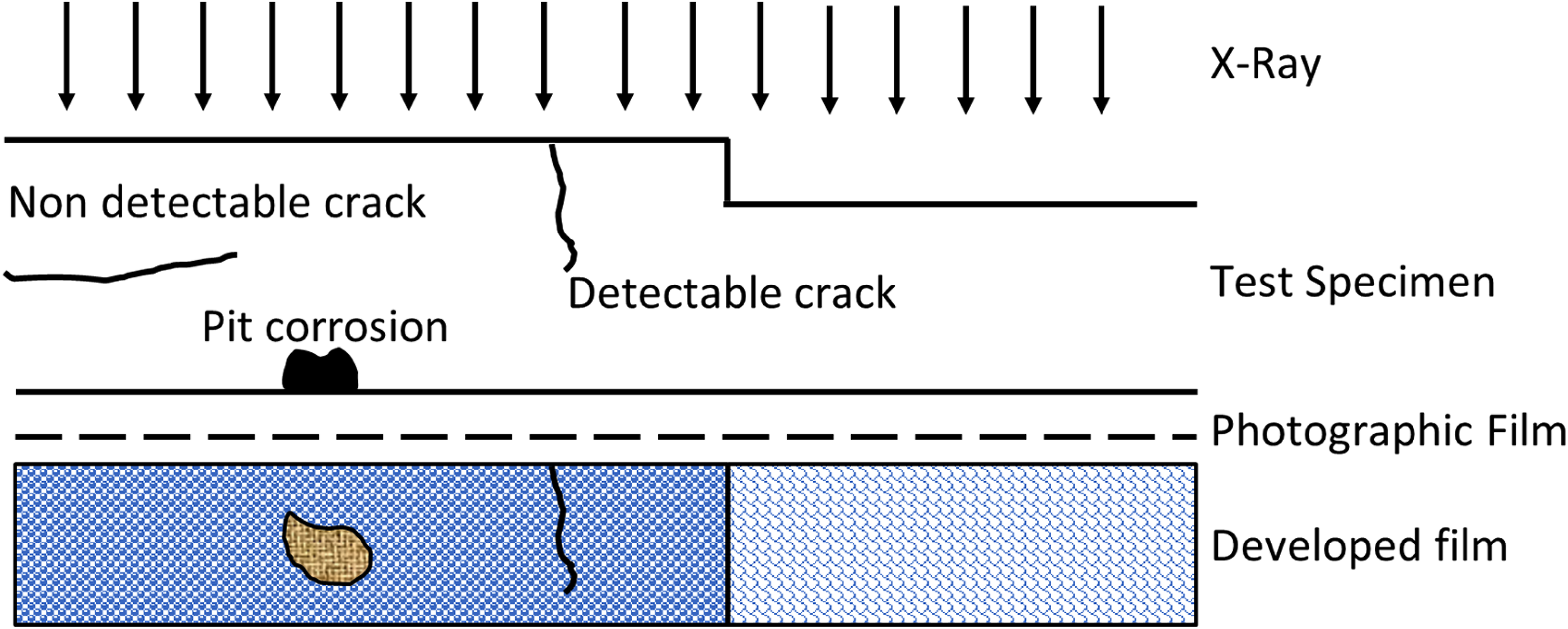
Principle of radiography (adapted from reference 42).
X-ray transmission radiography is one of the standard and early methods of radiographic NDT. The most fundamental characteristic of this technique is the type of tube used, among which the directional tube and the panoramic tube are most common. 150 In a directional tube, the radiations are emitted perpendicular to the long axis of the tube in a cone of 40°. However, in the case of the panoramic tube, the radiations are emitted in a complete 360° angle. In both types of tubes, the image contrast is determined by the attenuation characteristics and the thickness of the component that is being examined.4,151 Materials with a high atomic number, such as metals and alloys, have high attenuation, which increases the transmitted X-ray flux. This high contrast in the image is produced when there is pitting corrosion creating higher X-ray intensities.108,150,151
The other common source used is radioisotope or neutron source. Neutron radiography uses neutron attenuation determined by the scattering and absorption from the elements present in the component investigated. 152 For instance, hydrogen has high neutron absorption, and corrosion products mainly constitute hydroxides and moisture, which attenuates neutrons compared to the unaffected area. When used as the source for radiographic techniques, special care must be taken with radioactive isotopes. 153
Compton backscatter imaging (CBI) is a newly emerging technique primarily used to detect aircraft composites and metals and alloys flaws, for example, cracks, corrosion and delamination. Unlike the X-ray and radioisotope method, which measures the electromagnetic waves passing through the component, CBI measures the backscattered beam from the component to generate images. 154 CBI creates a tomographic image by raster scanning the component while the source-detector assembly is placed accurately parallel to the component testing.108,152
With computers and imaging software, it is possible to recreate a cross-sectional view of the component either in 2D or 3D form. More than one plane can be scanned, and with the aid of computers, these images are stitched together to recreate a 3D image. 155 This type of computer-aided radiographic technique is termed computed tomography or CT scanning. With these advanced systems, it is possible to detect defects such as wall thinning, accurately measure the size, shape and contours of the discontinuities in bulk.108,150,151
Rowe et al. compared the X-ray transmission radiography with neutron radiography to investigate corrosion on an aluminum alloy. In his studies, the X-ray method detected metal thickness changes as low as 0.8 mm, and the neutron method could detect hydroxide formed during corrosion. However, since the hydroxide layer formed during corrosion was three times thicker than the metal, neutron radiography was three times more sensitive in detecting the metal loss.156,157
The radiographic technique can be used over a large surface with high throughput making this technique rapid and reliable. The main advantage of using radio waves is propagating through any material.155,156 This method can detect different flaws, including corrosion, voids, and variation in density and thickness. This technique does not require contact with the component of interest, which makes it possible to inspect components that are not accessible. 41
Despite its advantages, this technique cannot determine the absolute value of thickness or defects in the components. The difference in optical density in the 2D radiographic image calculates the differences in thickness at specific areas inspected at regular intervals. 158 The radiographic images are dependent on the distance of the source to detection and the strength of the source. This imaging technique requires special care in the orientation and residual stresses.158–160
X-ray techniques, including radiography and X-ray fluorescence (XRF), can be utilised for corrosion monitoring by assessing changes in material properties, thickness or elemental composition.
The attenuation of X-rays refers to the reduction in the intensity of X-rays as they pass through a material. Attenuation is influenced by factors such as the energy of the X-rays, the density and thickness of the material, and the composition of the material. In general, if the attenuation of X-rays is high, it means that a significant portion of the X-rays is absorbed or scattered as they pass through the material. As a result, the transmitted X-ray intensity (the intensity of X-rays that make it through the material) will be lower. High attenuation usually implies strong absorption or scattering, leading to a reduced transmitted intensity.
If the attenuation of X-rays is high, it means that a significant portion of the X-rays is absorbed or scattered as they pass through a material. In this case, the transmitted X-ray intensity (the intensity of X-rays that make it through the material) will be lower. High attenuation implies strong absorption or scattering, resulting in reduced transmitted intensity.
The earlier source of radiation in X-ray imaging is typically an X-ray tube. In medical imaging, for example, an X-ray tube is used to generate X-rays. In industrial applications, X-ray tubes or other X-ray sources may also be employed. The X-ray tube produces X-rays when high-energy electrons are accelerated and collide with a metal target, usually tungsten. As for the earlier source of radiation, in X-ray imaging and industrial applications, an X-ray tube is commonly used. The X-ray tube generates X-rays by accelerating high-energy electrons and directing them to collide with a metal target, typically tungsten.
Regarding corrosion monitoring, X-ray techniques can indeed be used for this purpose. One common method is X-ray radiography. In this technique, X-rays are directed through a material, and the transmitted X-rays are detected on the other side. Changes in the material, such as corrosion or thickness variations, can be visualised based on the variations in X-ray attenuation. Another method is XRF, which can be used to analyse the elemental composition of materials. Changes in elemental composition, such as the presence of corrosion products, can be indicative of corrosion.
Microwave and millimeter-wave NDT
Microwave (MW) and millimeter-wave testing, which dates back to the late 1950s, has been recently recognised by the American Society of Nondestructive Testing (ASNT) as one of the new emerging NDT used in detecting defects in non-metallic surfaces. MW NDT is a technique that uses microwaves and millimeter waves as the source of energy. These waves can penetrate through non-conducting materials such as dielectric coatings, thereby enabling the underneath inspection without removing the coatings.161–163 However, the conductive materials such as metals reflect the microwave energy, limiting the inspection to the surface of such metallic components.161,164,165 The schematic shown in Figure 10 shows the principle of this technique.
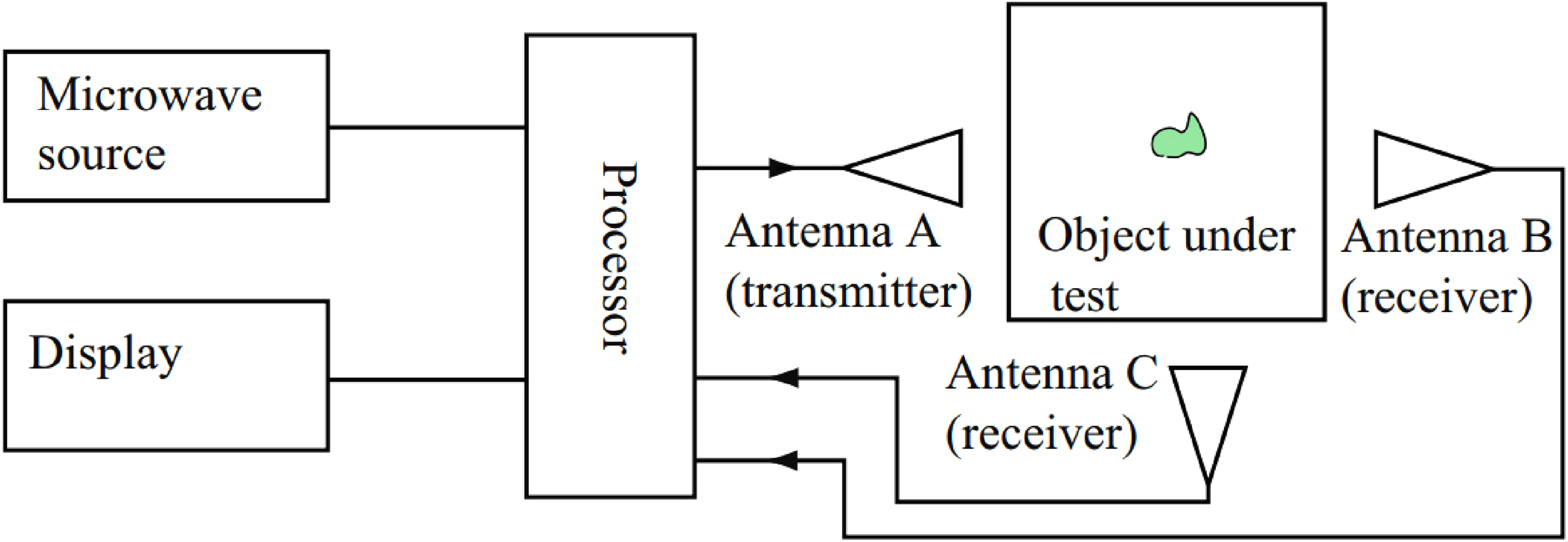
Principle in the detection of defects using microwave non-destructive technique through a scattering method (adapted from reference 166).
In general, MW NDT detects sub-surface cracks by observing the resonant frequency shift and the image of the magnitude, phrase and shift of the resonant frequency. The microwave frequency spectrum spans the frequency range from 300 MHz to 30 GHz, while the millimetre waves range from 30 to 300 GHz, corresponding to a wavelength of 1 m and 1 mm, respectively.161,167,168 There are different types of MW NDT used to measure and image the defect on the component. Among those, near-field MW, far-field MW and synthetic aperture radar imaging are a few of the common methods used to monitor defects in metals,169–173 composites174–178 and biomaterials.179,180 In near-field MW imaging, the probe and the component are placed at a very short distance, thus producing high resolution and high sensitivity to the defects in the component. There are different types of near-field probes including, open-ended rectangular and circular waveguides, open-ended coaxial lines, microstrip patches and cavity resonators, that provide unique advantages on specific applications. 161 However, as the distance between the component and the probe increases in near-field MW, the resolution and sensitivity rapidly degrade. Hence far-field technique is used in monitoring a thick component that requires the operation from a larger distance. In the far-field technique, an antenna with a focused beam is used to improve the resolution and sensitivity of the defects in the component. High-resolution delamination and voids defect detection through thick foam insulation samples using a lens and antenna are demonstrated. 168
The other form of imaging recreation technique uses backpropagation and synthetic aperture radar (SAR) algorithms to map 3D holographic images of dielectric structures. A fundamental principle of SAR imaging is demonstrated in Figure 11(a). 167 SAR uses a small antenna that moves either along 1D or across a 2D grid over a target region proving an image with special resolution. A successive pulse of radio waves are focused on the targeted image while the reflected echo pulse is measured at different angles of the sample. These reflected data is then processed to generate the required 2D or 3D images. Figure 11(b) demonstrates a comparison between an X-ray and a millimeter-wave (Ka-band, 26.5–40 GHz) SAR image of a fibre glass pipe joint structure. As seen in the image, the SAR millimeter-wave image shows a higher sensitivity to the non-uniform fibreglass structure in addition to the locations of missing adhesives as compared to the X-ray images. The main advantage of using SAR image processing is to generate real-time images, and hence it does not require any calibration, which makes this technique capable of on-line investigations.
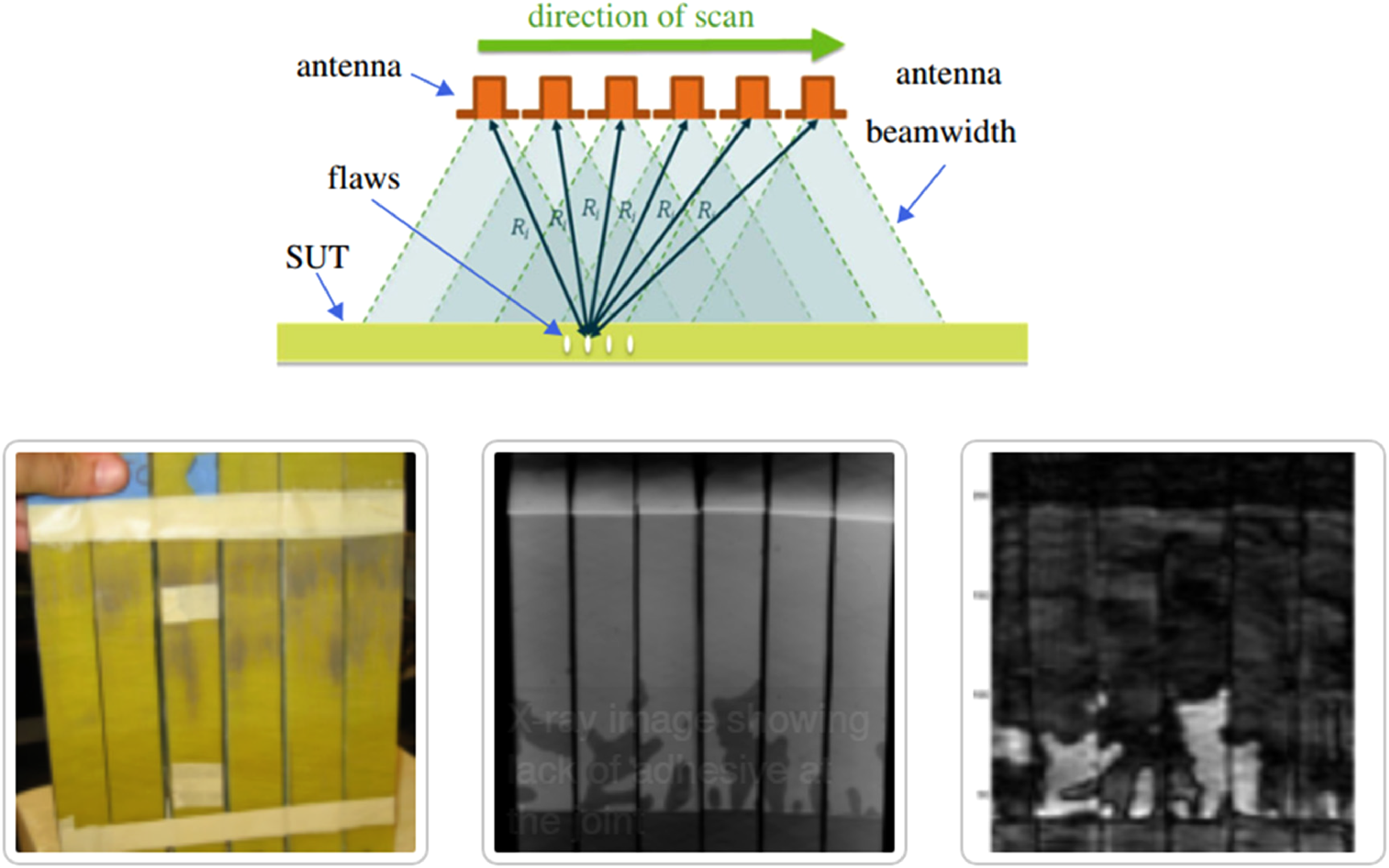
(a) Schematic representation of synthetic aperture imaging using a small antenna and (b) a comparison of a fibreglass pipe joint (left) between an X-ray and a millimeter-wave (26.5–40 GHz); sample and X-ray image are courtesy of Fiberglass Structural Engineering, Inc) (on-line version in colour) (adapted from reference 161).
Using this MW NDT allows obtaining qualitative information about the defects in the component and quantitative information such as the defect location, size and boundaries within the component.
Yu et al. 181 demonstrated a microwave measurement and imaging technique to characterise corrosion cracks in a metal component. A quantitative method to measure the defect was proposed with the imaging technique coupled with a canny algorithm. 181 Both numerical and experimental platforms were established to determine the type of corrosion, size and location of the defects.
Hugues et al. 182 demonstrated the detection of defects using Ka-Band (26.5–40 GHz) with V-band (50–75 GHz). His work also compared the effect of changing the bandwidth from Ka-Band to U-Band (40–60 GHz) and from V-Band to W-band (75–110 GHz). 182 Each band corresponds to an aperture opening with a higher band frequency, that is, the aperture opening is smaller. This method has been used to detect defects such as scratches, cracks and pitting. 147
The main advantage of using an MW NDT is that the microwave signal can penetrate a dielectric coating. MW imaging technique can reconstruct a complex profile of a component quantitatively of interest on both metal and non-metallic surfaces. Unlike ultrasonic methods, MW NDT does not require a coupling agent, and along with the lower requirement of detection, the environment makes it possible for this technique to be highly portable for on-line corrosion monitoring during the services of the component. Like other electromagnetic waves used for corrosion monitoring, the MW image resolution can be tuned by tuning for a higher frequency, and by tuning the frequency of microwave signals, it is possible to tune the depth of focus to measure the defects through the component, making it possible to evaluate from one side. This also eliminates the need for sample preparation, which significantly reduces the downtime and cost associated with the inspections. 183 High special resolution can be obtained by tuning the microwave reflectometry band and the aperture openings. With the decrease in aperture dimensions and maintaining a low frequency, Hugues et al. demonstrated an increased special resolution on aluminum substrates.182,184
Kharkovsky et al., 185 using focused and synthetic imaging techniques, focused on three recent applications of microwave and millimeter-wave NDT to detect disbonding between carbon fibre within a concrete structure, corrosion detection on aluminum and steel substrates as well as the flaws in insulation foam.
Terahertz imaging
Terahertz (THz) NDT is an electromagnetic wave that utilises a frequency range between 0.1 to 10 THz, corresponding to the wavelength range of 0.03 to 3 mm between the microwave and infrared. Materials that are opaque to visible and infrared light are transparent to terahertz radiations. The defects are determined by analysing the changes in THz wave at or near the radiation source after the interaction with the component. THz waves have better penetration through non-metallic components which makes it possible to use to monitor defects underneath a coating. These waves can travel through opaque materials which can be made use to detect the internal defects which cannot be detected using visual light. Since THz has a shorter wavelength than microwave radiation, THz has higher spatial radiation along with not posing any known harm to living organisms.
THz are divided into pulse and continuous wave (CW) THz methods. Pulse THz is the electromagnetic picosecond pulses having a spectral range from 100 GHz to several THz, which offers an advantage of broad spectral information from a single scan. The most popular pulse THz uses an optical gating photoconductive antenna (PCA) illuminated using a laser source for THz generation and detection. A typical pulsed THz is illustrated in Figure 12, where a femtosecond (fs) laser emits sub 100 fs pulses that split into an emitter and a detector arm. A large aperture PCA generates the THz pulses. The beam of THz waves is focused on the component using a parabolic mirror or a polymeric lens which is then reflected by the sample layers and the aluminum substrate. The reflected beam is then collected by another parabolic mirror sent to a ZnTe crystal where it overlaps with the beam from the probe. This method records the reflected THz's waveform and preserves phase and amplitude information. This technique typically offers a signal-to-noise ratio, calculated as the mean signal divided by its standard deviation, which is between 1000 to 2000. 163
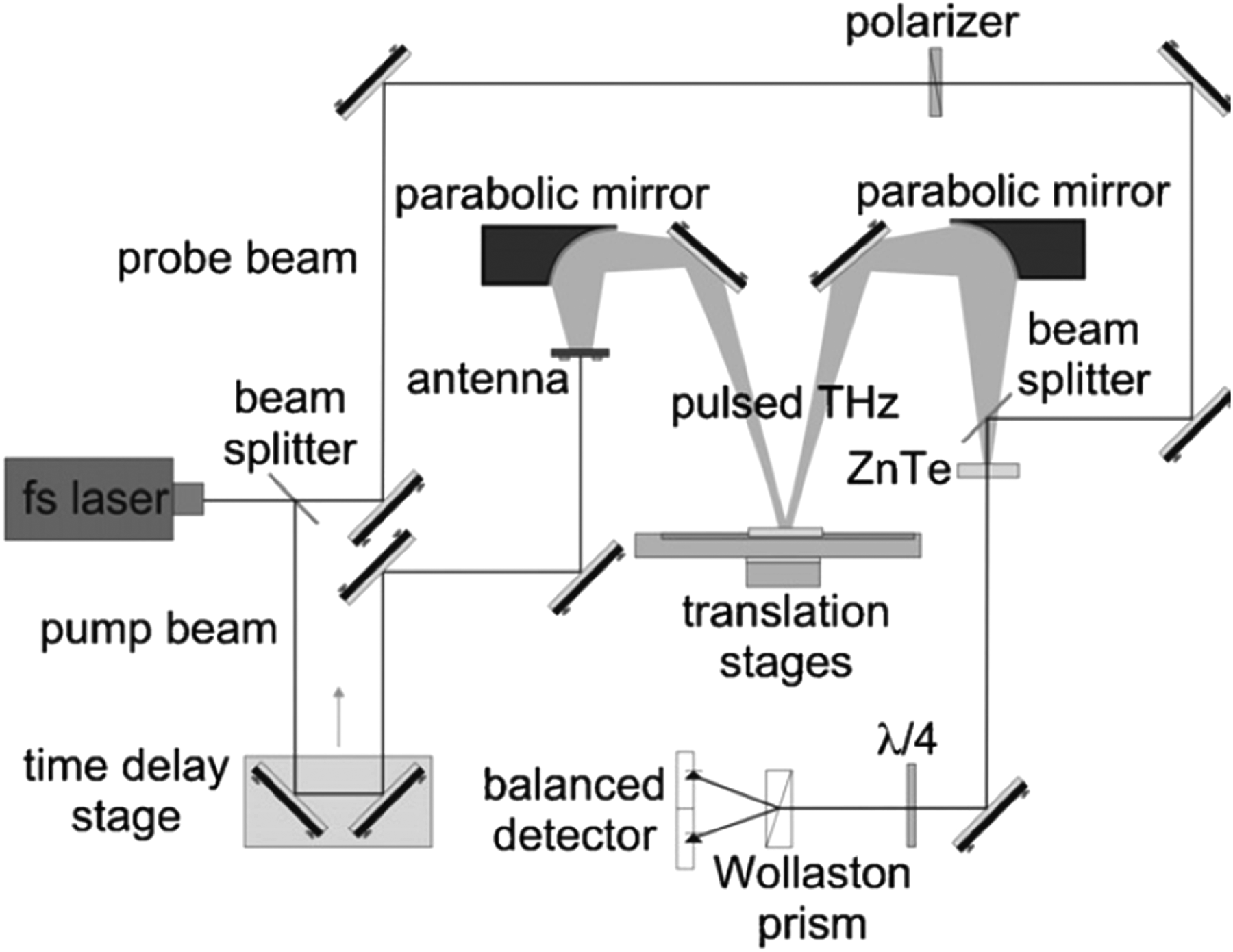
Typical setup of pulsed terahertz (THz) (adapted from reference 186).
A typical setup of CW THz is shown in Figure 13. In a CW THz, an oscillator emits the THz beam. The oscillations are created in several ways, including electronic methods, 163 optoelectronic via photomixers,164,165,187 quantum cascade lasers 188 and backward wave oscillators. 189 The emitted THz beam is focused through a parabolic mirror that passes through a chopper to a polyethylene Fresnel lens, typically at a focal length of 204 mm. 163 The distance between the parabolic mirror and the lens determines the spot size and the focus point. The component to be inspected is placed at this focus point. The reflected beam from the component is focused through a spiral lens, typically made with polyethylene, to a detector. The signal from the detector is then analysed by a lock-in amplifier. The intensity data are simply stored in a matrix that is directly converted to a raster image.
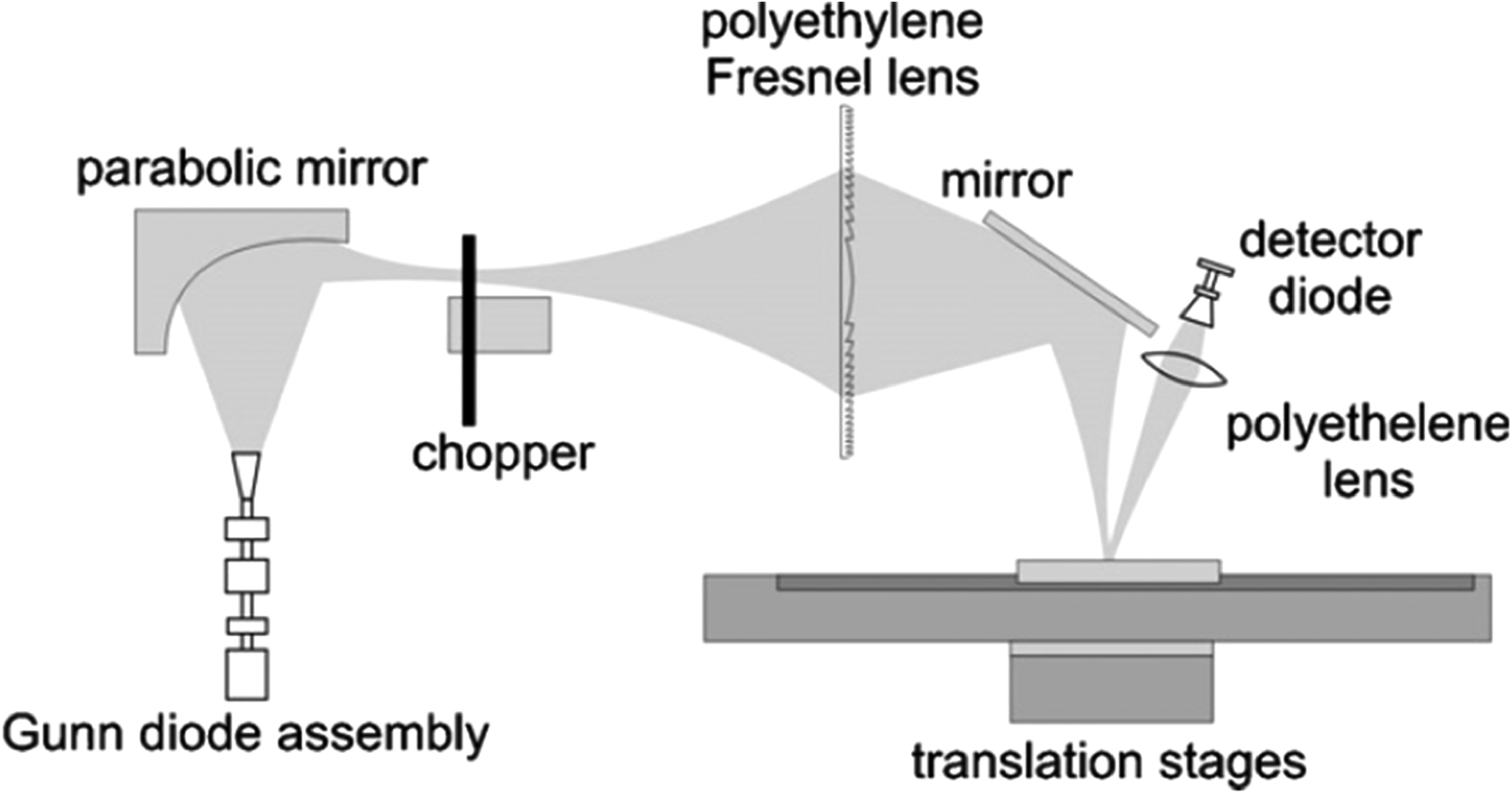
A typical setup for continuous wave terahertz (CW THz) non-destructive technique method (adapted from reference 186).
These two methods are wisely chosen to meet the requirements between simplicity and adaptability. While the pulse THz method has several detailed information on the defect, CW yields only the intensity data and does not provide any depth, frequency-domain, or time-domain information while the component in the investigation is exposed to a single frequency. However, the CW has the advantage of a compact, fast (does not require time delay scan – hence image formation is quick) and relatively low-cost system, and plots obtained from transmitted energy are sufficient for several imaging applications. The complexities of optics involved are significantly reduced in CW THz compared to pulse THZ making this technique a screening tool in most applications. The main advantage of the pulsed THz method is that detailed information is recorded with one measurement, and it can be precisely used to find the required information for each application. The pulsed THz method becomes vital where the imaging is precisely tied to the time-domain information. Table 1 summarises the main differences between the pulse and CW THz.
Comparison between continuous wave THz and pulsed THz methods.
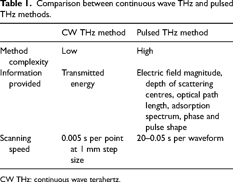
CW THz: continuous wave terahertz.
The THz has been prototyped using corrosion detection in space shuttles under the shuttle tile. 104 Work from Anastasi et al. 104 showed that THz was successful in detecting corrosion under a shuttle tile depth of more than 0.13 mm. As compared with FTIR, THz has the advantage of using the phase and amplitude of the waveform to calculate the refractive index and the absorption coefficient of the component. THz can also be applied on a multilayer component using the time domain waveforms without a coolant to the detector.
Comparison of different non-destructive methods
Table 2 gives an overview of the common NDT methods mechanism, its advantages, and disadvantages. This review is a brief overview of several NDTs available in the literature. In lieu of describing the technical and practical nuances of each method, a large number of references are provided for the interested reader.
Brief overview of the NDTs discussed in this review.
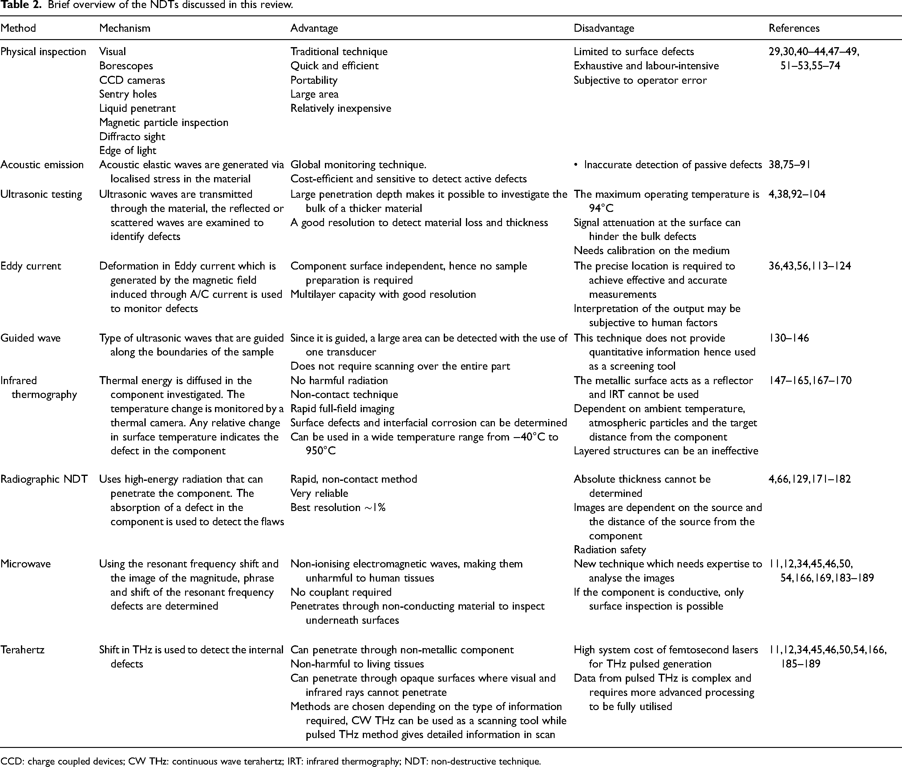
CCD: charge coupled devices; CW THz: continuous wave terahertz; IRT: infrared thermography; NDT: non-destructive technique.
The extent of error in measuring defects, including the depth of corrosion damage, can vary depending on the NDT method used, the equipment quality, the specific conditions of the inspection, and the skill of the operator. Each NDT method has its own capabilities, limitations and associated measurement errors. Ultrasonic testing (UT) is commonly used for measuring the depth of corrosion damage. The accuracy of depth measurements can be high, often within a few millimetres, especially when performed by trained and experienced operators using advanced equipment. ECT is effective for surface and near-surface inspections. The depth resolution is typically good, and measurements can be accurate within a certain range. However, the accuracy may be influenced by factors such as material properties and the size and shape of the defect. X-ray and radiographic testing: These methods are excellent for visualising internal structures and defects but may have limitations in accurately determining the depth of corrosion damage. The resolution is influenced by factors such as X-ray energy, material thickness and the quality of the radiographic image. MPI is primarily used for detecting surface and near-surface defects. It's effective for ferrous materials, and the accuracy of depth measurements depends on factors such as defect size and magnetic field strength. Dye penetrant testing (PT) is more suitable for surface defects, and it may not provide accurate depth measurements. It is mainly used for detecting cracks, porosity and other surface irregularities. It's important to note that while these methods can provide valuable information about defects and corrosion damage, the interpretation of results and the accuracy of measurements often rely on the expertise of the inspector. Additionally, factors such as material properties, surface conditions and the specific environment can influence measurement accuracy.
Calibration is a crucial aspect of ensuring the accuracy and reliability of instruments used in corrosion monitoring. Each type of technique listed below has its own calibration procedures.
Visual and optical testing (LP, MPI, D-sight, EoL): Calibration in visual and optical testing involves verifying the accuracy of measurement scales, ensuring proper lighting conditions, and checking the performance of optical instruments. Calibration blocks with known features (such as notches or artificial defects) may be used for this purpose.
AEs: Calibration in AE monitoring involves using controlled sources of acoustic signals to verify the sensitivity and accuracy of the monitoring system. Calibrated AE sources or reference sources are used to simulate events, and the system response is compared to known values.
Ultrasonic monitoring methods: Ultrasonic instruments are calibrated using reference standards with known dimensions and acoustic properties. Calibration involves adjusting the instrument settings, such as velocity and gain, to ensure accurate measurements of material thickness and the detection of flaws.
EC: EC instruments are typically calibrated using reference standards with known electrical conductivity and defect characteristics. Calibration involves adjusting instrument parameters to ensure accurate identification and characterisation of material properties and defects.
GWs and equipment: Calibration of GW equipment involves verifying the proper functioning of transducers and ensuring that signals are accurately transmitted and received. Calibration standards, such as calibration blocks with artificial defects, are used to confirm the reliability of the system.
IRT: Infrared cameras used for thermography are often calibrated using blackbody radiation sources with known temperatures. This calibration ensures accurate temperature measurements and thermal imaging.
Radiographic NDT: Radiographic instruments are calibrated using reference standards, including test objects with known thicknesses and discontinuities. Calibration ensures accurate exposure times and the proper interpretation of radiographic images.
Microwave and millimeter-wave NDT: Calibration of instruments in this category involves using precision standards to verify the accuracy of measurements and the resolution of the equipment. Calibration blocks with specific geometries and materials may be used.
THz imaging: THZ imaging systems are calibrated using reference standards, often involving known materials with specific absorption characteristics. Calibration ensures accurate imaging and interpretation of terahertz signals.
In all cases, the calibration process involves comparing the instrument's response to known standards or reference materials. Regular calibration is essential to maintain the accuracy and reliability of corrosion monitoring instruments over time. Calibration intervals may vary based on the specific requirements of the technique and the instrument used.
The sensitivity of detection and accuracy can vary based on factors such as equipment quality, operator expertise, material properties and specific application conditions. The values in the table provide a general overview and may not be universally applicable to all scenarios. It is recommended to consult specific guidelines, standards and experts in the field for accurate information related to a particular application. Below is a table summarising the application, sensitivity of detection and accuracy for each of the listed corrosion monitoring techniques (Table 3).
Summary of the application, sensitivity of detection and accuracy for each of the listed corrosion monitoring techniques.
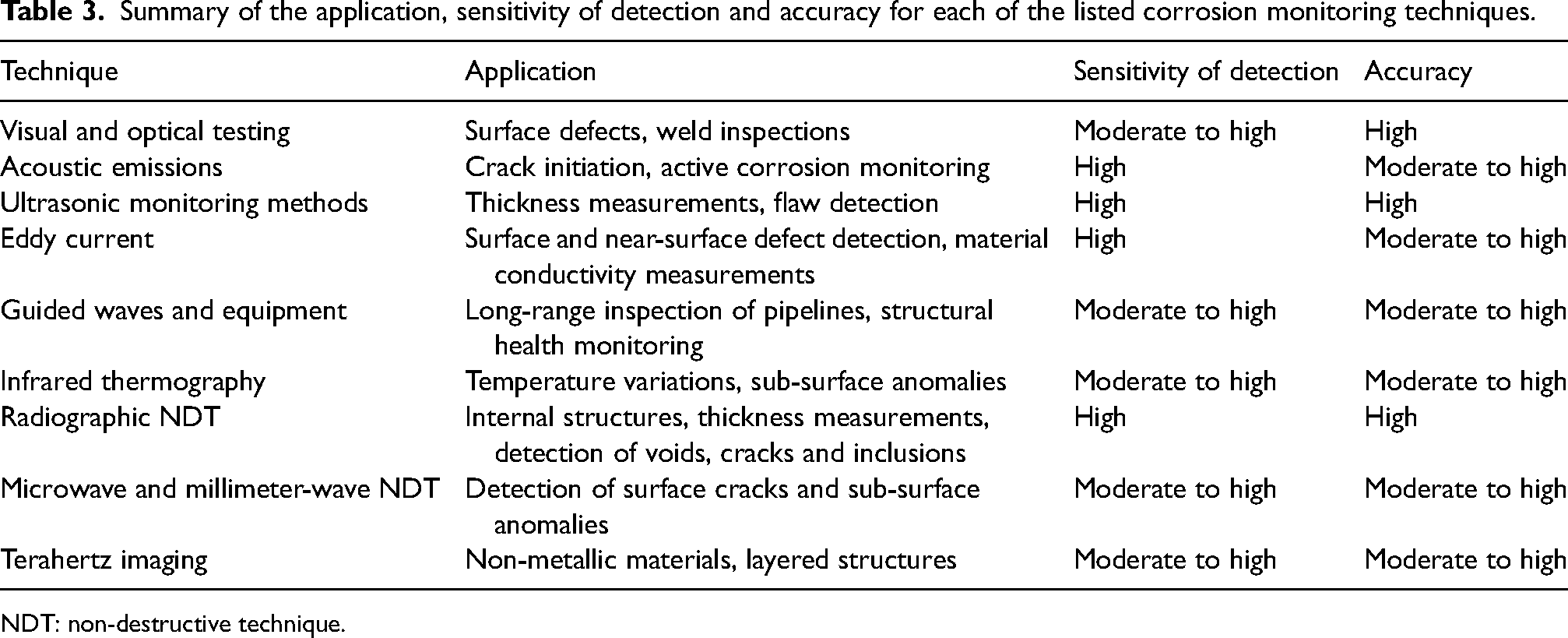
NDT: non-destructive technique.
In critical applications, it is common practice to perform validation and calibration exercises to determine the measurement accuracy of the NDT method for a particular scenario. This ensures that the inspection results are reliable and meaningful for making informed decisions about the integrity of structures or components.
Summary and conclusions
In summary, multiple component corrosion failures in the structures are fatal threats to structural health. Therefore, the critical focus of corrosion science and engineering over the past few years is validating the integrity through monitoring and inspection without any destruction or damage and enabling the component's preservation without substantial economic impact. The corrosion process is dependent on several factors, including the material selected, heat treatment, the exposed environment and the contaminants in the materials themselves. Understanding the type of corrosion is essential to employ appropriate technologies for detection and characterising corrosion. Because the corrosion type is dependent on the area where it occurs in a component, the material and the condition under which it occurs, no single inspection method can be employed to detect all possible forms of corrosion.
The corrosion prediction can either be preventive or corrective measures on the component, whereas, preventive measures are usually scheduled to repair and service the component before the failures. Corrective measures are retroactive strategies where the scenario is to replace an affected part of the component.
Visual methods are good at screening surface defects. When examining the under-surface defects, reliability is a concern while using the visual examination. Hence, other advanced techniques can be combined with a visual inspection.
The AE technique monitors the flaw growth rate early in localised corrosion, especially for inaccessible defects. On the other hand, the ultrasonic method is primarily used to characterise the type of defect being a non-contact method. EC has a good potential as a screening tool to monitor the depth size.
The techniques mentioned in this article are all NDT methods, used across various industries to inspect and assess the integrity of materials and structures without causing damage. Each of these techniques has its strengths and limitations, making them suitable for different applications across a wide range of industries. Here's a brief overview of their applications.
Visual and optical testing
Application industries: Aerospace, automotive, construction, manufacturing. Reason: Visual inspection is fundamental and widely applicable. It is used for detecting surface irregularities, cracks, corrosion and other visible defects. Application industries: Aerospace, automotive, petrochemical, welding. Reason: It's effective for detecting surface-breaking defects, such as cracks and porosity. After applying a penetrant and a developer, the indications become visible. Application industries: Aerospace, automotive, rail, power generation. Reason: It's used for detecting surface and near-surface defects in ferromagnetic materials. Magnetic particles gather at defect locations, making them visible. Application industries: Semiconductor, electronics, precision manufacturing. Reason: These methods are employed for inspecting very small and precise components where traditional methods may not be suitable. Diffractosight can be used for surface roughness measurement. Application industries: Structural monitoring (e.g. bridges, pipelines), pressure vessels, aerospace. Reason: Used to detect and monitor the release of stress waves caused by structural defects or changes, helping identify potential failures. Application industries: Oil and gas, petrochemical, aerospace, manufacturing. Reason: Ultrasonic waves are used to detect internal defects, measure thickness, and assess material properties. It's versatile and widely used for its ability to penetrate materials. Application industries: Aerospace, automotive, power generation, electronics. Reason: Used for detecting surface and near-surface defects, and also for measuring material thickness. Particularly effective for conductive materials. Application industries: Oil and gas (pipelines), aerospace, structural monitoring. Reason: GWs travel along structures, allowing for the detection of defects over longer distances. Effective for inspecting long pipelines and structures. Application industries: Electrical, building inspection, manufacturing. Reason: Measures infrared radiation to detect variations in temperature. Used for identifying overheating components, insulation issues and other anomalies. Application industries: Aerospace, oil and gas, construction, manufacturing. Reason: Utilises X-rays or gamma rays to inspect the internal structure of materials, detecting voids, cracks and other internal defects. Application industries: Aerospace, electronics, telecommunications. Reason: These techniques use microwave and millimeter-wave frequencies to inspect dielectric materials and detect defects in composites and electronic components. Application industries: Pharmaceutical, materials science, security. Reason: THz waves can penetrate many materials while providing detailed images, making it suitable for detecting internal defects in pharmaceutical tablets, composites and more.
LP testing
MPI
D-sight and EoL
AEs
Ultrasonic monitoring methods
EC
GWs and equipment
IRT
Radiographic NDT
Microwave and millimeter-wave NDT
THz imaging
Overall, predicting and monitoring corrosion is an essential tool for preserving material health and reducing the life-cycle cost of the infrastructures. Typical modelling in the understanding of corrosion has not been made partially due to its multi-disciplinary phenomenon that exists in many forms and combinations of corrosion that occurs based on the material, and the environment to which that material is exposed. Typical corrosion finding and detecting begin with a visual inspection. Any damage observed through visual inspection requires a closer look with sophisticated techniques for closer evaluations.
When selecting a corrosion monitoring technique, it's essential to consider the specific requirements of the inspection scenario, including accessibility, environmental conditions and the need for on-site or field inspections. The portability of the equipment can play a crucial role in the feasibility and efficiency of the corrosion monitoring process. Portability is an important factor in selecting a corrosion monitoring technique, as it can impact the ease of use and applicability in different scenarios. Here's a breakdown of the portability of each technique:
LP
Portability: Highly portable.
Reason: Liquid penetrant testing involves simple application and does not require bulky equipment. It is suitable for on-site inspections and field applications. Portability: Portable, but equipment size can vary. Reason: Portable magnetic particle inspection equipment is available, making it suitable for on-site inspections. However, the size of the equipment can vary based on the application. Portability: Generally portable. Reason: Diffracto sight equipment is typically compact and can be transported to different locations for inspections. However, the exact portability may depend on the specific device used. Portability: Portable. Reason: EoL techniques often use handheld devices or portable equipment, making them suitable for on-site inspections and field applications. Portability: Portable. Reason: AEs monitoring equipment can be portable and is suitable for monitoring structural integrity in various environments. Portability: Portable. Reason: Ultrasonic testing equipment is available in portable forms, allowing for on-site inspections. The equipment may vary in size and complexity. Portability: Portable. Reason: EC testing equipment is generally portable, making it suitable for on-site inspections and examinations of conductive materials. Portability: Portable but may require specialised equipment. Reason: Portable GW equipment is available, but it may require specific setups and considerations. It is suitable for inspecting long structures. Portability: Portable. Reason: Infrared cameras used for thermography are often handheld and portable, making them suitable for on-site inspections and monitoring. Portability: Generally less portable. Reason: Radiographic equipment, such as X-ray machines or gamma ray sources, can be bulky and require controlled environments. Portable options exist but may have limitations. Portability: Portable. Reason: Microwave and millimeter-wave NDT equipment can be portable, suitable for inspections in various industries. Portability: Portable, but equipment can vary. Reason: THz imaging equipment can be compact and portable, making it suitable for certain applications, but the exact portability depends on the device used.
MPI
D-sight
EoL
AEs
Ultrasonic monitoring methods
EC
GWs and equipment
IRT
Radiographic NDT
Microwave and millimeter-wave NDT
THz imaging
In addition, artificial intelligence(AI) and machine learning (ML) are increasingly being integrated into various industries, including NDT and corrosion monitoring. AI and ML might impact each of the corrosion monitoring techniques, with a forward-looking perspective. For LP, AI and ML can be used to analyse and interpret liquid penetrant inspection results more efficiently, automating defect detection and classification. ML algorithms can learn from historical data to improve accuracy and reduce false positives. For MPI, AI and ML can enhance defect detection by analysing MPI images. ML algorithms can learn to identify and classify defects, improving accuracy and speed. Integration with AI may lead to more automated and reliable inspections. For D-sight, AI and ML could assist in the analysis of D-sight data, helping to interpret complex patterns and identify defects. ML algorithms could be trained on various patterns, improving the system's ability to detect subtle changes. For EoL, AI and ML can be applied to analyse edge of light data for corrosion monitoring. ML can help identify and classify corrosion patterns, providing more accurate and faster results. Automation can lead to increased efficiency in the inspection process. For AEs, AI and ML can analyse AEs data to detect patterns associated with corrosion or structural degradation. ML algorithms can learn from acoustic signatures, improving the ability to identify and predict potential issues. For ultrasonic monitoring methods, AI and ML can enhance ultrasonic testing by automating defect recognition and classification. ML models can analyse ultrasonic waveforms to identify corrosion or other anomalies, improving the accuracy and speed of inspections. For EC, AI and ML can be integrated into EC testing to analyse complex signals and detect subtle changes indicative of corrosion. ML algorithms can learn from diverse datasets, improving the system's ability to adapt to various materials and conditions. For GWs and equipment, AI and ML can assist in the analysis of GW data, helping to identify and locate corrosion or defects in long structures. ML models can improve the accuracy of defect localisation and sizing. For IRT, AI and ML can enhance the analysis of IRT images. ML algorithms can learn thermal patterns associated with corrosion, enabling automated detection and classification. Integration with AI can lead to quicker and more accurate assessments. For radiographic NDT, AI and ML can be applied to radiographic data for automated defect recognition. ML models can assist in identifying and classifying defects in radiographic images, improving efficiency and reducing the need for manual interpretation. For microwave and millimeter-wave NDT, AI and ML can analyse microwave and millimeter-wave NDT data for corrosion detection. ML algorithms can learn from different material properties and corrosion patterns, improving the accuracy of inspections. For THz imaging, AI and ML can enhance THz imaging analysis. ML algorithms can improve the identification and classification of defects, leading to more accurate corrosion assessments. Automation can streamline the inspection process.
In summary, the integration of AI and ML into corrosion monitoring techniques holds great potential for improving accuracy, efficiency and automation in the inspection process. These technologies can assist in analysing complex data, detecting subtle patterns and providing more reliable insights into the condition of materials and structures. The forward-looking perspective involves continued advancements in AI capabilities, increased use of real-time monitoring, and the development of smarter, more adaptive inspection systems.
Footnotes
List of abbrevations
Declaration of conflicting interests
The authors declared no potential conflicts of interest with respect to the research, authorship, and/or publication of this article.
Funding
The authors received no financial support for the research, authorship, and/or publication of this article.