
Abstract
In regions with limited access to CAD/CAM machines like Latin America, academic experiences have adapted digital tools to local capabilities, aiming to enhance project creativity through digital technology. This article examines the use of timber as a material, addressing the technical, spatial, and cultural aspects related to its use, while intertwining the educational narrative of learning through doing and adapting. The structures designed in this research are based on three key parameters: timber as the main material, framing as a discrete design system and side-by-side joints as a vital component of the traditional fabrication process. Through the integration of digital and traditional techniques, the aim is to adapt methods frequently used in digital design and manufacturing processes. This study emphasizes that merging digital tools with traditional construction knowledge can lead to innovative solutions, especially in areas with limited digital resources, showing that digital fabrication can broaden and enrich traditional building methods beyond just being a numerical alternative.
Keywords
Introduction
Digital design and manufacturing encompass any computer-controlled process. In the 21st century, we are witnessing the dawn of a new post-digital era 1 where nothing is exempt from the use of digital technologies. In architecture, this development goes beyond being a mere numerical or virtual alternative to traditional analogue design and manufacturing techniques and has significantly changed the relationship between design and construction. This change has a profound impact on both processes and the conception of projects. 2 A relevant example of these changes is the compilation of cases presented by Gramazio and Kohler in their book The Robotic Touch: How Robots Change Architecture. This book illustrates by specific cases the redefinition of creative and formal possibilities by means of robotic technologies. 3 What is more, it also transforms the way in which the two processes are linked and collaborate, generating a profound impact on the perspective and territory from which they are conceived. 4
Under this local vision, in scenarios with limited access to Computer Aided Design (CAD) and Computer Aided Manufacturing (CAM) machines, like much of Latin America, designers have had to adopt digital tools and focus their approaches on existing capabilities. In this article, we analyse this approach, highlighting how the combination of territorial conditions and digital technologies can lead to solutions that have the potential to be innovative in different contexts, and attempt to show the potential and versatility of these tools, especially within educational experiences with undergraduate students from the Universidad Austral, Chile. We will seek to put into practice the idea of Neil Gershenfeld, that digital manufacturing is a form of analogue manufacturing controlled by digital means. 5
As a team at Dum Dum Lab, we have put a lot of effort into disseminating decentralized knowledge of computational design technologies, specifically in regions significantly distanced from the capital of Chile. And, as we have already mentioned, two of the biggest complications in designing collaborative installations in the national territory are the access to materials and the availability of manufacturing means, especially for larger installations. In the beginning, all the elements to be built in each of the workshops carried out met the condition of being able to be transported by air. This is where the material challenge comes into play: how to increase the scale of the projects without losing the logic of computer design and digital manufacturing?
Timber plays a fundamental role here. Chile has a growing timber industry that provides access to industrial timber almost everywhere in the country. 6 Chile has a tradition of timber construction, especially in the south, developing cultural and academic links with this material. This technical and cultural base makes it possible to focus research on timber with more confidence. How to bridge the gap in the absence of digital tools? Is it possible to maintain computational processes with traditional manufacturing, as Gershenfeld mentions?
Therefore, the projects presented here seek to innovate in the adaptability offered by current digital technologies, establishing a methodology that does not start with the final form, but rather with the recognition of the available material and manufacture inputs as fundamental variables in the project as shown in Figure 1. Rationalisation of the geometrical and constructive flow of timber construction systems. (a) Traditional timber truss (b)Geometrical analysis of the standard truss. (c) Parameterisation of the truss system (d) Form-finding exploration.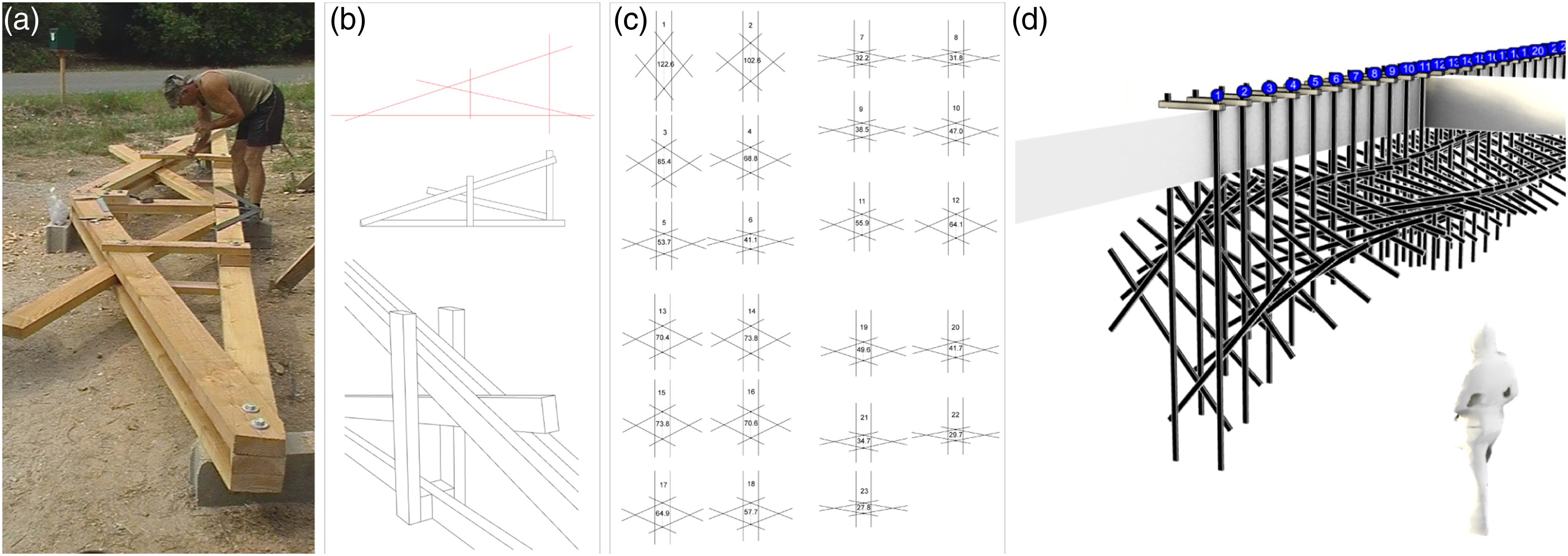
Adaptation process
The interaction between contextual constraints and digital technologies provides a unique opportunity to develop a technology appropriation protocol that aims to achieve an adaptation that results in a flexible and suitably adaptable methodology.
Drawing on three key approaches to design materialisation – Materials-Oriented Design, Fabrication-Based Design and Computational Design – it is proposed to address the territorial challenge in which we operate. These models, as Rivka Oxman 7 points out, are design approaches where the combined potential of material design and manufacture plays an essential role in design conception. From this modelled perspective, three constants were identified as essential to our approach: timber battens as the primary material, framing as a discrete design system, and side-to-side joints, borrowed from traditional fabrication. This strategy allows the projects carried out by the team to establish a constant negotiation between the variables recognised in the context, such as material and fabrication, and the technological means available. The adaptation of these systematised approaches has been essential to effectively address the complexities inherent to the territory and to the materialisation of the design.
Material-oriented design (MOD)
MOD is a design model that emphasises the specific properties and characteristics of materials when approaching the design process. Rather than considering material as simply an aesthetic or functional choice, Material Oriented Design focuses on using the intrinsic properties of the material to inform and shape the final design. As an office, when approaching any design process, the first constraints are related to the available material and its associated technical properties. MOD allows the properties, characteristics and behaviour of materials to be used as active drivers of design. 8
As already stated, this article focusses on the research carried out by the office, where timber is the main material. It is therefore important to take into account, from the outset, the structural characteristics of the material, such as its strength in relation to its weight, its ability to withstand loads in different directions, its flexibility, its durability and its ability to absorb shocks, etc. In addition, this biomaterial offers a wide range of applications. It can also be used at a wide range of scales, from small architectural details to massive structures, not to mention its high tectonic value. 9
This last characteristic, tectonic, allows us to recognise the potential of local precedents. In these construction methods, it is possible to identify trusses, grids and framing, among other systems. These structures allow for a more relevant and appropriate approach to the use of the resource. Such lightweight structures are an example of a context that lacks technological tools and wood-based materials. Consequently, the analysis of these construction systems is part of a strategy that seeks to be relevant and aware of the possibilities offered by a raw and discrete material such as timber.
Fabrication-Based Design (FBD)
The use of digital fabrication has become a common medium in design processes 10 and has reconfigured our experience of the material world. 11 However, as we have described in this article, these media have not yet permeated all regions of the Global South in the same way. 12 In Chile, for example, most CAD/CAM machines are located in the capital city or in cities close to it. 11 Due to this territorial situation of unequal access to digital technology, it is necessary to rethink the way in which the design and manufacturing process is conceived.
For this reason, as a studio, we have adopted FBD (Fabrication-based Design) as another primary approach to our design methodology. It places fabrication, usually considered at the end of the process, as one of the primary steps in the design process. FBD can be understood as a methodology in which manufacturing methods are prioritised from the beginning of the design process. Designs are also adapted to the available manufacturing technologies, be they digital or traditional, in order to achieve effective and efficient production. In short, this approach reveals the links between the properties of materials, their performance, and the strategies and methods for transferring them into physical reality. 8
The design process therefore starts from the premise that manufacturing should be a universal, feasible and adaptable process within a defined context, and is the first opportunity to explore the form and intentions of the project. The FBD allows the design process to admit the emergence of new approaches that result from the mediation between technology and local technical and human capacities. It gives rise to particular formal characteristics in each project, directly related to the circumstances of a geographical, cultural and economic context. This is a result of the interdependence between technology, technical resources and available materials.
The approach to the fabrication system governs the potential of projects, focussing on the concept of ‘node’ or ‘union’, crucial in speculative research for the past 8 years. Linked to linear materials, the ‘node’ extends beyond technical fabrication and assembly to influence relationships and variations, thereby guiding geometric definitions. Through the logic of similarity, it explores variations while maintaining constructiveness and efficiency. Success in iterating forms requires a thorough understanding and it is essential to have prior control of the node’s complexity and connectivity.
Computational design (CD)
The workflow adopted by the office seeks to improve the exploratory capacity of construction systems. The change of focus during the design process offered by computational methods, where it is possible to handle reciprocal processes between input and output values, allows for an informed design capable of anticipating and foreseeing possible complications, thus designing not only a form, but rather a behaviour, that is, a system. This system seeks to resolve the complexities inherent in the interrelationship and interdependence of material structures and dynamic environments. 13
Following this bottom-up logic, the constraints, and properties of materials, as well as their possible joints, can be encoded and incorporated into the logics from the outset, allowing controlled and materialisable forms to be proposed. Computational design therefore allows us to rethink constraints not as a problem per se, but as a generative driver in the design process. In conclusion, the control established at the beginning of the design process allows the project to be solved not only by digital fabrication but also by traditional fabrication. Furthermore, this implies that the context, material, economic, technical and cultural, become descriptive rules for the process of a design. Updating and making relevant the act of designing and the act of building.
Academic, material, and technological context
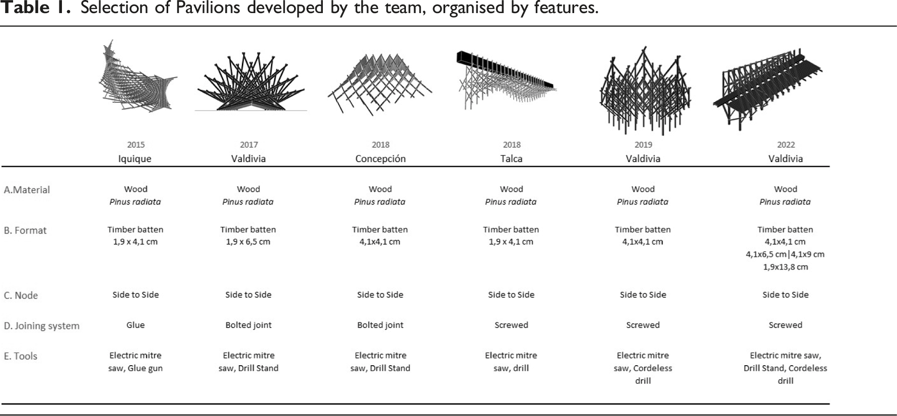
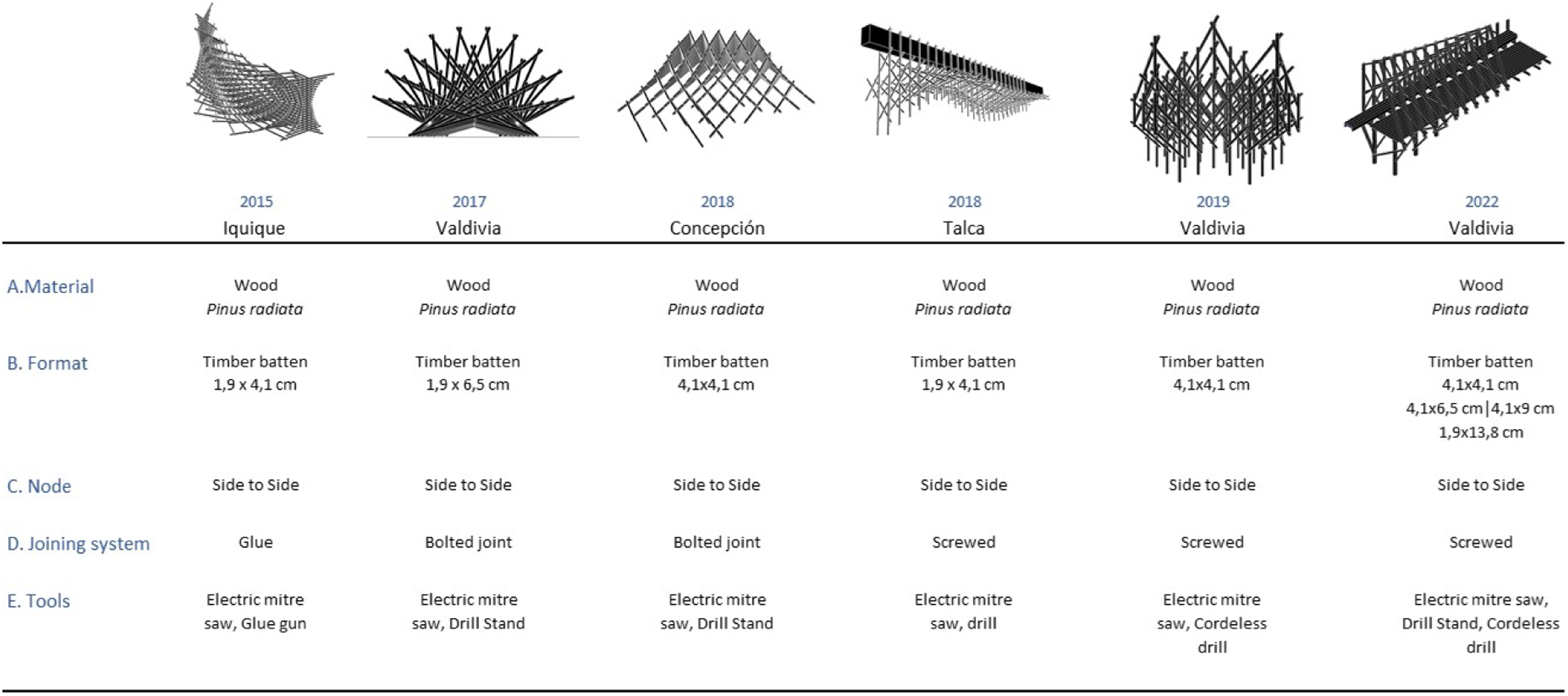
Selection of Pavilions developed by the team, organised by features.
The collaboration described in this article took place at the Architecture School of Universidad Austral in the city of Valdivia. This institution is notable for its academic focus on wood-based architectural design, which is strongly linked to the building tradition of Southern Chile, where timber is the predominant material in its built heritage. However, despite the close relationship with timber and traditional design, a gap was identified in the school’s academic curriculum in relation to the integration and use of advanced technologies in digital design.
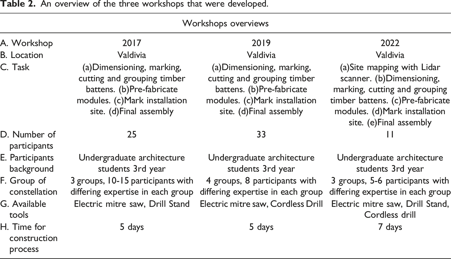
An overview of the three workshops that were developed.
Particular emphasis was placed on the importance of going beyond the exploration of digital designs in a virtual environment, considering that it was essential that, in each of the workshops to be carried out, the students would be involved in the construction of real scale (1:1) structures. This hands-on phase aimed to solidify and apply their knowledge, offering a chance to confront real-world construction challenges and validate their digital learning.
Main comparative features of the case studies.
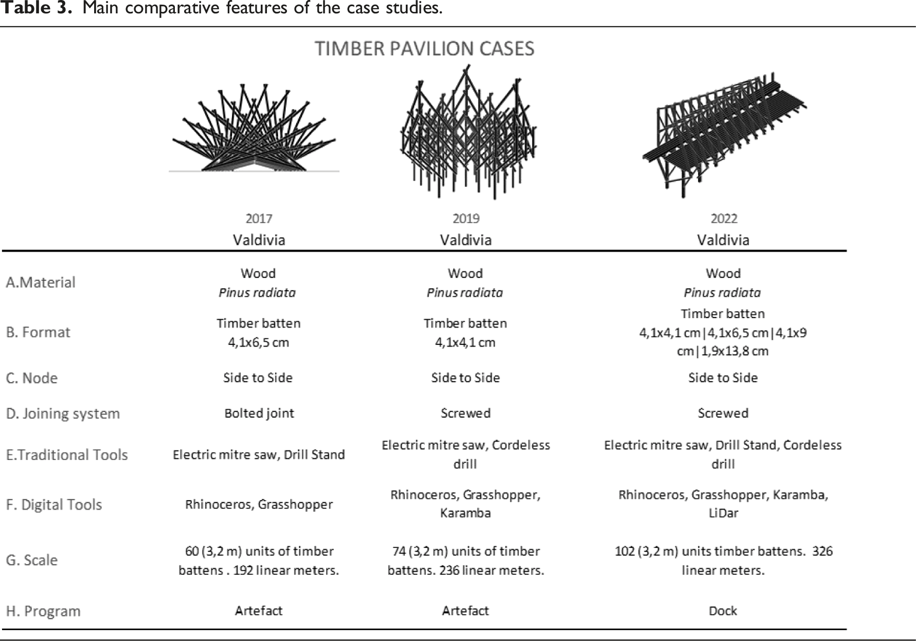
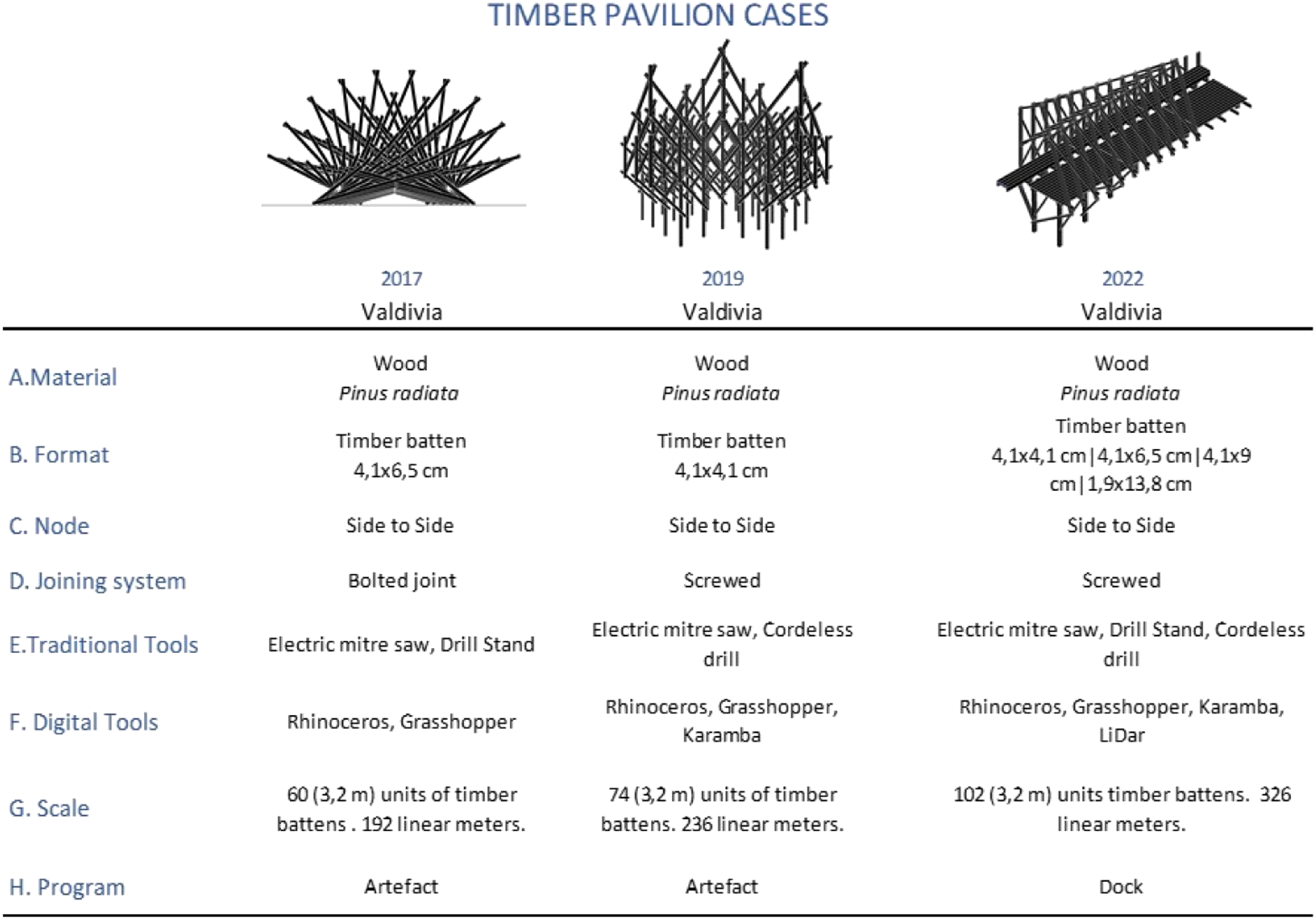
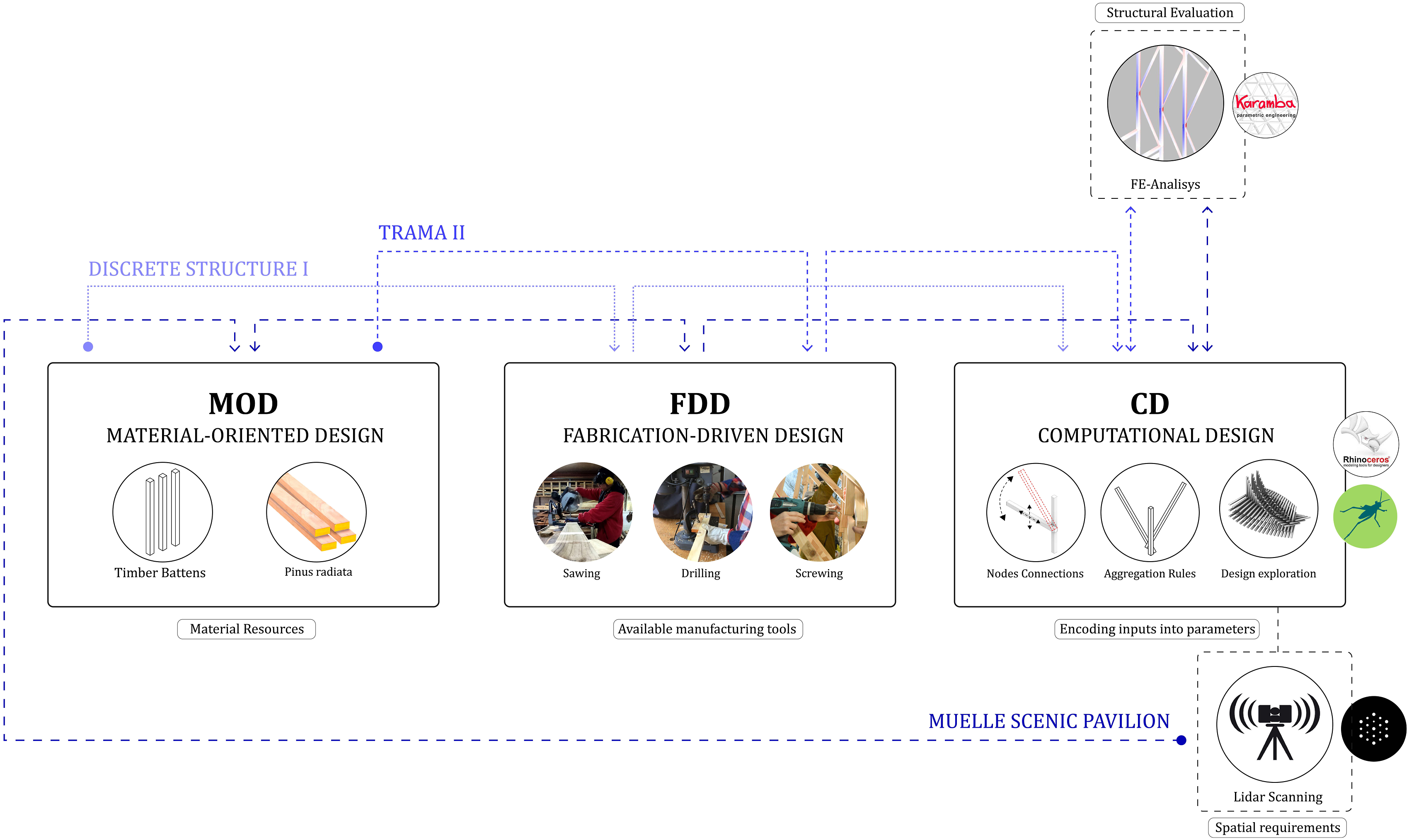
With this in mind, it was decided to use the above-mentioned MOD + FBD + CD adaptation methods to identify elements and improve their capabilities (Figure 2). a. Material-oriented design: Spatial structures in timber as primary material, focussing on the use of softwood elements, specifically planed Pinus radiata. This type of timber was chosen due to its predominance in the national timber industry, which ensures easy availability and access to the material. In 2020, Pinus radiata will account for 97.2% of Chile’s national production, with Oregon pine being the second most important species with a share of only 1.4%.
15
b. Fabrication-based design: Due to the traditional tools in the wood laboratory, the design utilized face-to-face joints and 90° wood cuts. This approach aimed to use generic assemblies executable with traditional tools, avoiding the need for CNC tool angle cuts or mechanized joints. c. Computational Design | Reciprocal process: The design methodology developed for each workshop shares the material and fabrication constraints mentioned above, incorporating them in a codified manner as starting inputs inside the platform of visual programming GrasshopperAs the complexity and scale of the last two experiments grew, structural analysis with Karamba 3D
16
software was integrated into the design process. Additionally, a Lidar (Light Detection and Ranging) scanner was used for the final installation to account for the irregular slope of the site. Workflow adopted for the design of the three cases. Development of the Adaptation Methodology.
Another reason for selecting these three cases is that they provide a consistent contextual perspective. This makes it easier to identify variations between the three workshops. In addition to differences in the projects themselves, there were also evolutions in the amount of software implemented, as well as in the scale and functionality of the projects.
Workshop process
In the framework of the proposed workshop as shown in Figure 3, an initial dynamic focused on familiarising students with the Rhinoceros and Grasshopper environments, based on the basic concepts of visual programming; introduction to the user interface and navigation of panels, menus and toolbars. Also, the creation of basic geometries with points, lines, and surfaces; the difference between components and parameters; manipulation of parameters to modify geometries, among other exercises. Workflow carried out in the 3 case studies, divided in stages and scopes.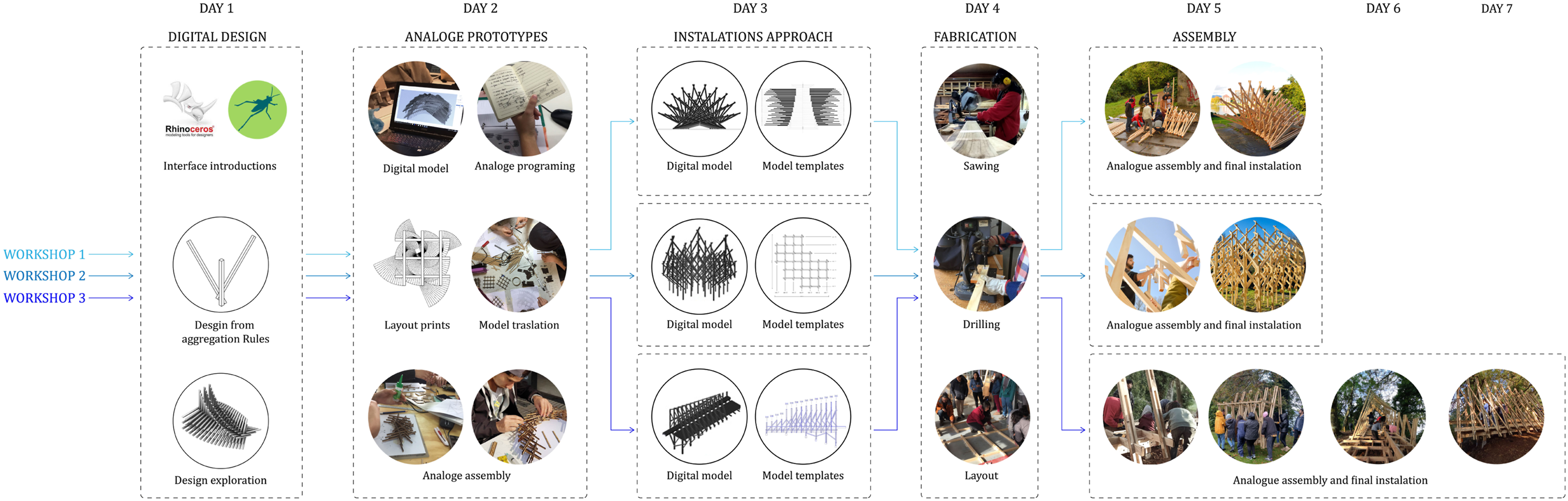
In a second phase, work was based on linear elements, understood as discrete components, and the establishment of possible connection nodes between them. The aim of this first stage was to facilitate the understanding of the interactions between different discrete components and how they can be programmed using aggregation rules in the visual programming interface.
Once the connection constraints between these nodes were established and understood, we then proceeded to a phase of sequential manipulation of the aggregation parameters. At this stage, we sought to delineate potential design spaces within a standardised digital environment. During this phase, successive transformations were applied to the elements, including translations, rotations and scaling of the initially proposed linear elements. This series of concatenated operations provided an initial approach to form finding techniques under design constraints.
In a practical transition of this digital knowledge, the exploratory exercises carried out on the first day were materialised into physical prototypes the following day. These prototypes, made from 2 × 4 mm model sticks, were meticulously cut by hand to the dimensions extracted from the previous digital model. This process was aided by 2D printed templates, which provided precise details of the positioning and assembly of each component (Figure 4). The aim of this analogue phase was not only to materialise the design but also to introduce the students to the complexity inherent in the transition process between a digital model and its realisation in a tangible prototype. Methodology for approaching manufacturing exercise. Material/Node/Shape Search/Fabrication.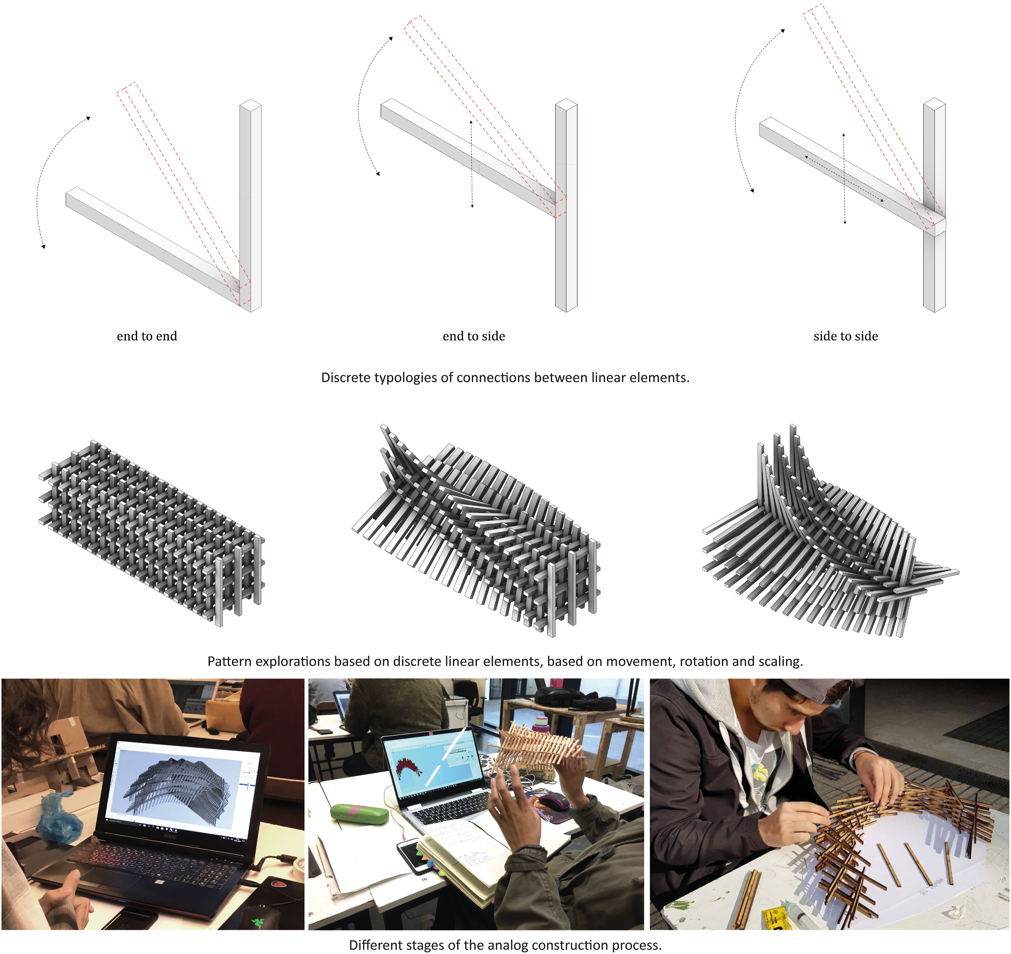
After the initial aggregation design exercises in the workshops, the next phase consists of dissecting and understanding the geometric and modular systems of the final installations to be built, focussing on node connections, aggregation rules and the use of different planes and axes. Discrete Structure I presents a simple node on a single axis with progressive rotations, resulting in a linear construction. The Trama II Pavilion evolves this concept, incorporating three axes of growth and two planes of rotation to achieve a more complex and reticulated form. The Muelle Pavilion further refines the system, using specialized nodes for different structural functions, culminating in a robust structure with defined interior spaces (see Figure 5). (a) Configuration of nodes based on axes and variation planes (b) variation on face-to-face assemblies in each pavilion.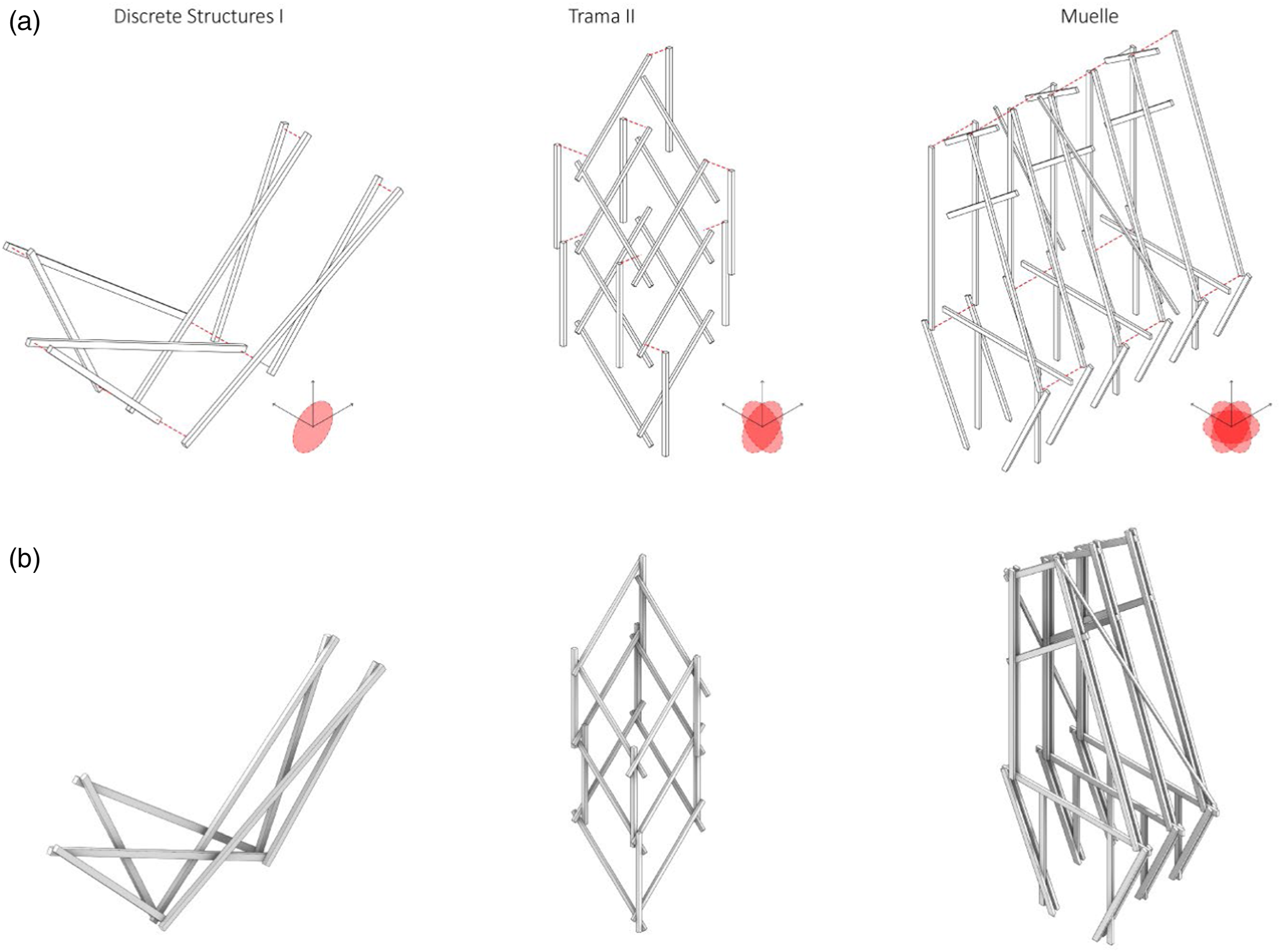
These digital and analogue exercises are primarily designed to make the participants aware of the underlying logic behind the design of 1:1 scale installations, which they will be expected to carry out in the subsequent workshops. It is important to note that, although the final installations have been pre-designed by the team, they are also intended to be experimental fields for the students, allowing them to engage with notation systems, the categorisation of pieces and the production of planimetries. All these elements are necessary to understand and carry out the following manufacturing and assembly tasks.
The third day was dedicated to training in the use of tools in the woodworking laboratory. Afterwards, different working groups were formed, one dedicated to the cubing and preparation of the planimetries for the prefabrication of the wooden components, and the other to the assembly of the first components.
The duration and scope of the workshops varied according to the complexity of the structures to be built. The first two workshops took place over 5 working days, while the third workshop, given the challenge of developing a habitable structure of greater dimension and complexity, provided for an additional 2 days of assembly work, as planned at the time of programming the activity in 7 days.
The work logistics described above are intended to encourage all the students taking part in the workshops to be involved in most of the stages of the process, thus achieving a common learning process and promoting collaborative work to achieve each stage. The aim was not only to transfer specific techniques and skills but also to instil a deep understanding of the integral process of design and construction, from its digital conceptualisation to its physical materialisation.
Case studies
The following case studies are based on the same design methodology, but they differ in terms of their spatial and formal criteria. The first case focussed on the formal and constructive exploration of a truss with sequential rotation variations, thus limiting its habitable possibilities. In the second case, the main objective was to generate a light and elevated volume that would minimize contact with the ground, thus maximizing the structural capabilities in the use of small section timber. For the third case, priority was to create a habitable structure, which meant incorporating a floor area as a pier, complemented by trusses that create a semi-open and functional interior space. These approaches reflect an evolution in design criteria, from non-habitable and form-limited structures to more complex and habitable solutions, demonstrating a progressive exploration of spatial possibilities.
Discrete Structures I
Discrete Structures I (2017) is the first pavilion in this selection of three. The general aim of the project was to construct a material installation of complex form, but with low technical resolution. To this purpose, the methodology of adaptation was applied:
Material-Oriented Design (MOD): As in the three case studies, industrial timber is the basic material for all the pavilions. In this case, 4,1 × 6,5 cm unplaned timber was used. So, already knowing the properties of the material, the approach to form was adapted to budget and difficulty.
Computational Design (CD): The design under the software Grasshopper begins by generating a series of elliptical curves that share the same axis of displacement and vary their radius incrementally. The upper zone of each ellipse is subdivided by points from 2 to 10, which are then connected by lines that interweave these points and are extended to provide space for point fixations. From this basic truss system, inscribed in the ellipse, the longest elements are controlled (with a maximum market length of 320 m), and a pattern of subdivisions and angles is determined that share linear axes at the bottom (See Figure 6(a)). Finally, these lines are used as central box axes with sections of 4.1 × 9 cm, dimensions that in turn determine the spacing between each axis lines. (a)Diagrams of angles variations and front view of the structure. (b)Nodes definition and assembly of components.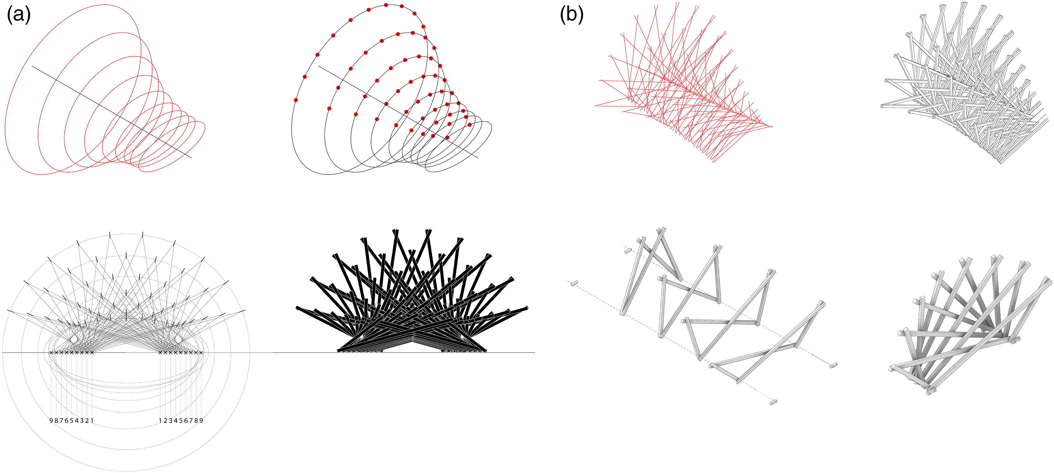
This approach allows the exploration of different possible configurations and shapes, leading to careful iteration and refinement of the design. Every subdivision and angle are explored to find a balance between structural stability and efficient use of materials. The chosen configuration consisted of nine independently reinforced modules (Figure 6(b)). Each module in turn increases the number of points to a total of 10. The angulations depended on the projection of a point between the division on the horizontal axis and a variable point on the outer ellipse. In this way, the control of the different angles made it possible to progressively extend the projection of the points, while maintaining structural stability in its 2 axes of support on the ground (See Figure 7(a)). (a)Sequence of assembly process. (b)Record of assembly progress. Image adapted from Homo Faber 2.0 (Scheeren R et al. Homo Faber 2.0: Politics of the digital in Latin America. 2018.).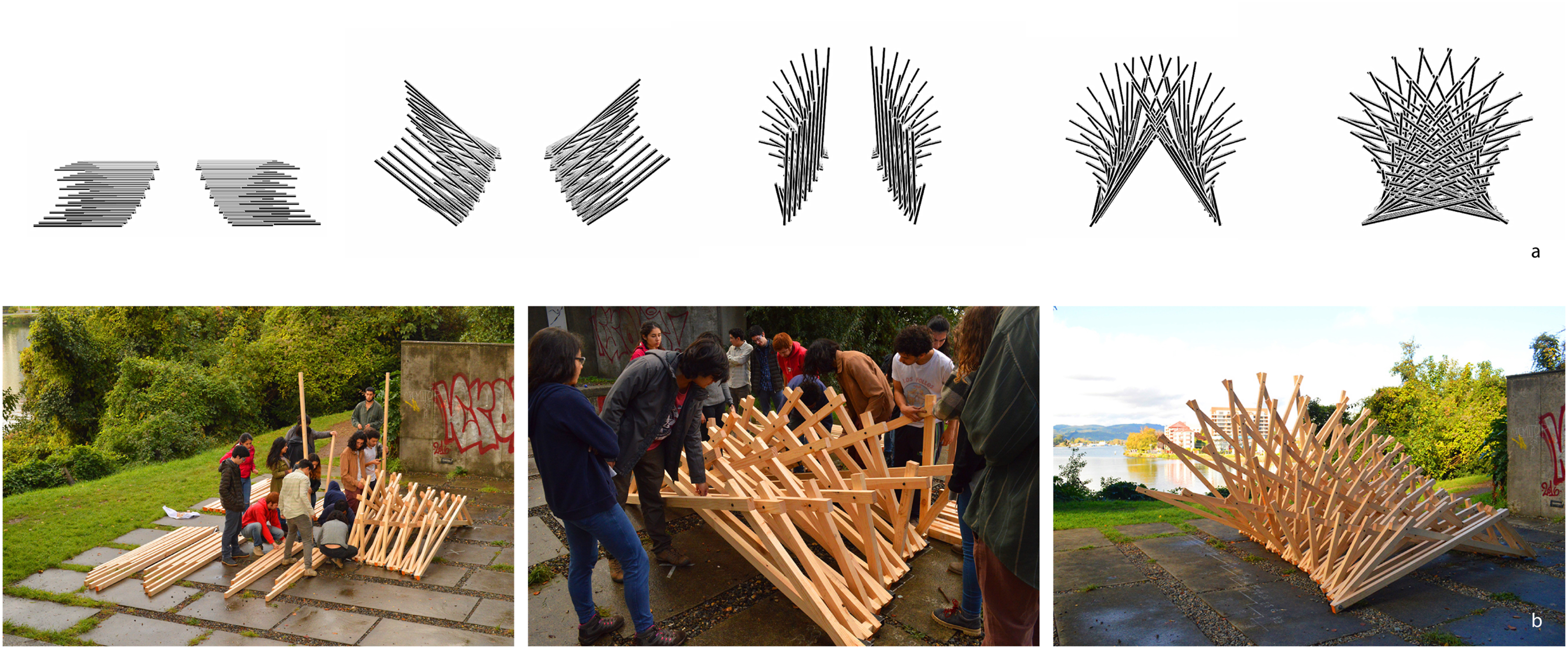
Fabrication-Based Design (FBD): This consolidation of joints on two axes facilitates a continuous connection by means of an endless bolt. Such a node allows rotation in a single plane and linear growth perpendicular to this plane.
For the construction of the pavilion, 90% of the timber was cut with an electric mitre saw at a unique 90° angle. All these pieces of wood were cut on site in a prefabrication phase that took two days. On the other hand, the remaining 10% are metal elements of two types: ten pairs of worm screws for the axles and 20 standard pieces of square metal tube for the spacers. In fact, it is these metal elements that allow the lateral connection to be efficient, articulated and adapted to the junction.
All the metal parts designed for this project were manufactured in the city of Valparaiso, so their dimensions could not exceed those allowed in an aircraft bag (approximately 70 cm long, 45 cm wide and 28 cm deep). The modularity of the trusses was therefore limited by these metal parts (Figure 7(b)).
Trama II
The second case study is the Pavilion Trama II (2019), which was part of the research for a larger project called Trama I for an international architectural competition. The initial phase of research for this Pavilion focused on discovering the potential for modularity in stereometric structures. Specifically in linear timber elements with the initial constraint of using face-to-face joints.
Material-Oriented Design (MOD): The timber used in this exercise consisted of 4,1 × 4 × 1 cm planed timber. This profile allows easy manipulation, with fast cutting and a screwing joints system that does not require much effort. The formal exploration begins with a linear growth sequence, based on elements oriented on the z-axis, with the possibility of lateral growth by means of diagonal axis couplings, in the pursuit of a closed grid structural module.
Computational Design (CD): The computational design sequence involves a first approach from aggregation rules between vertical and diagonal linear elements at 40° projection to the XZ and YZ planes. This aggregation rule is repeated until completing a module closed by 4 verticals and 4 diagonals (Figure 8(a)), establishing face-to-face intersection nodes. This initial module is rationalized by defining a container box of 100 × 100 cm base and 80 cm height with edges and diagonals representing the axes of the wooden slats (Figure 8(b)). This rationalization allows to explore larger groupings within a considerably lighter digital model (Figure 8(c)), when finding organizations of interest, we proceed in reverse to restore the components as 3D components (Figure 8(d)). Module aggregation rules and rationalisation module.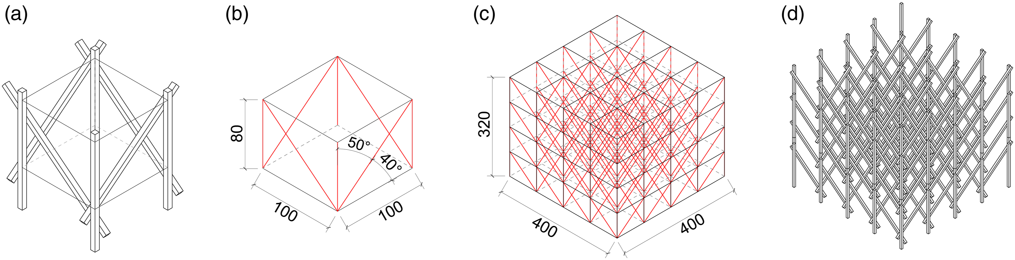
The workflow was enriched with the structural analysis offered by Karamba 3d (Figure 9(a)). Deformations under compression and tension were analysed, allowing the structural performance to be optimised without limiting the most creative versions. With this project, it is possible to demonstrate that the replicability and adaptability of the system is optimal, since the Trama I project mentioned above follows exactly the same construction logic, only adapting the node to the structural requirements. Trama II, (a)Form-finding and structural analysis. (b)Sequence of aggregations. (c) Node catalogue.(d) Construction process.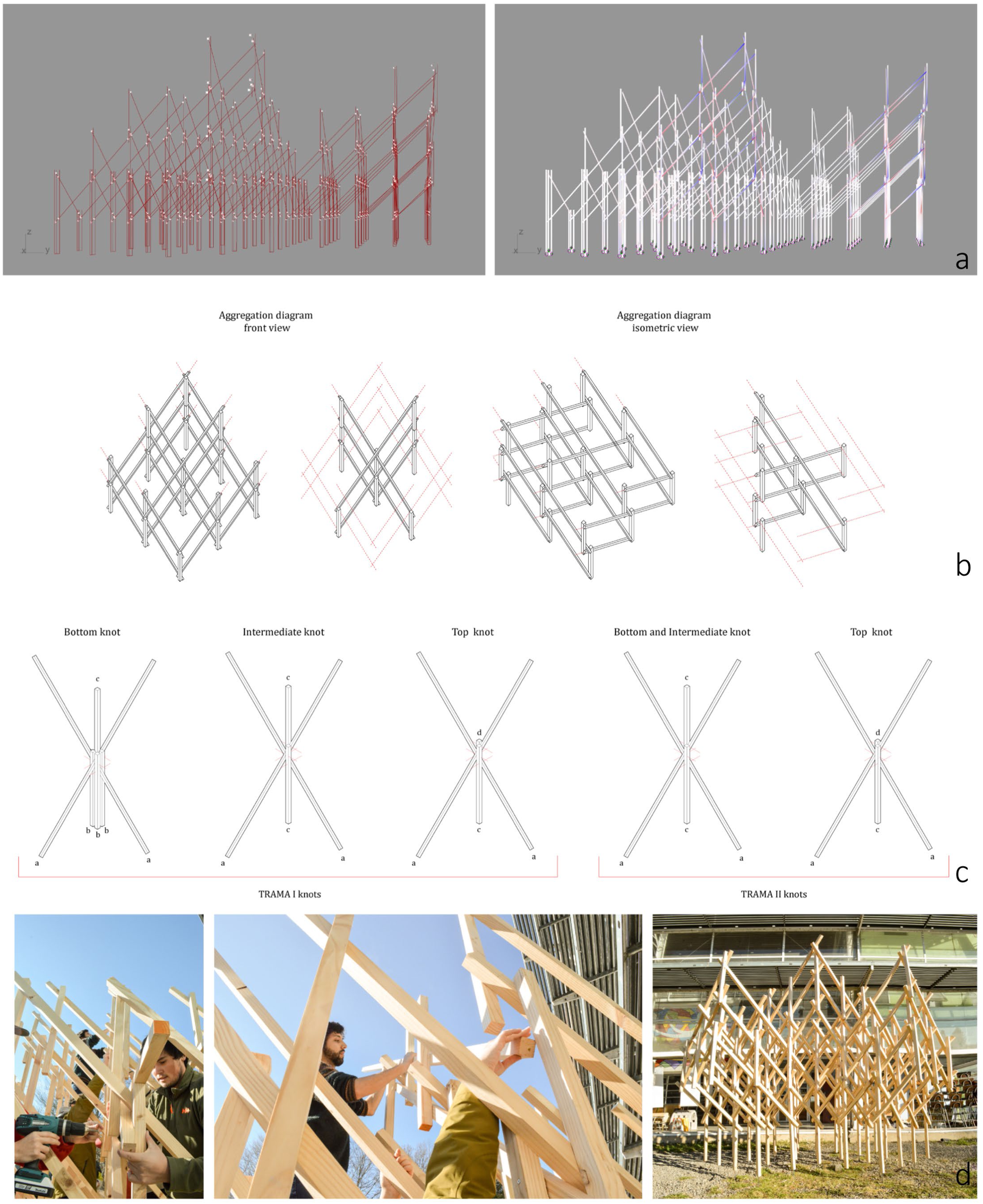
Fabrication-Based Design (FBD): The aim was to develop generic assemblies that could be fabricated using traditional tooling. This avoids the need for CNC tools or steel joints as in the previous case. As a result, the pavilion allows for a more three-dimensional grid-like formation, made up of light timber elements that together give robustness to the entire system (Figure 9(b)). The spatial complexity is thus obtained from a simple constructive logic, three axes of growth and two planes of rotation. Based on this result and the basic analysis of the structural behaviour, a single type of node was defined to be used throughout the project (Figure 9(c)).
The prototype was built from a total of 74 3.2 mt wooden battens, cut to 9 different sizes with an electric mitre saw at a single right angle. The whole system was organised by assembling seven sections, connected by continuous diagonals (Figure 9(c)). Design based on fabrication allows examples like this, where the complexity of the shape is based solely on the relationship of its parts. Again, the simplicity of the node and the discrete elements allow for a clear and precise notational system, making the organisation of the assembly simple and quick (Figure 9(d)).
Muelle, scenic pavilion
Finally, the last case, Muelle (2021), is part of a project of three different pavilions located on a riverbank in the same city. Although this project had a slightly larger budget, it presented a slightly more complex requirement. This particular pavilion had to be located on an uneven site with an irregular slope. The aim was to create an access at ground level, a viewpoint that would progress in a linear fashion on the uneven terrain. The site context therefore became a significant constraint.
Computational Design (CD): The initial phase of material investigation was complemented by a map of the site using a Lidar scanner (Figure 10(b)). The creation of the occupation grid allowed the difficulties and opportunities of the site to be identified and a site strategy to be developed. As a result, it was decided that the structure would be a pier, so the landings would have to be punctual supports to sustain a habitable platform. Once the basic constraints on the possible location and scale of the pavilion had been established, the material research process began (Figure 10(a)). (a) Diagrams of geometric parameters and components in front view (b) Lidar scanning incorporated in digital design model (c) Nodes and module sequence organization (d) Record of assembly progress.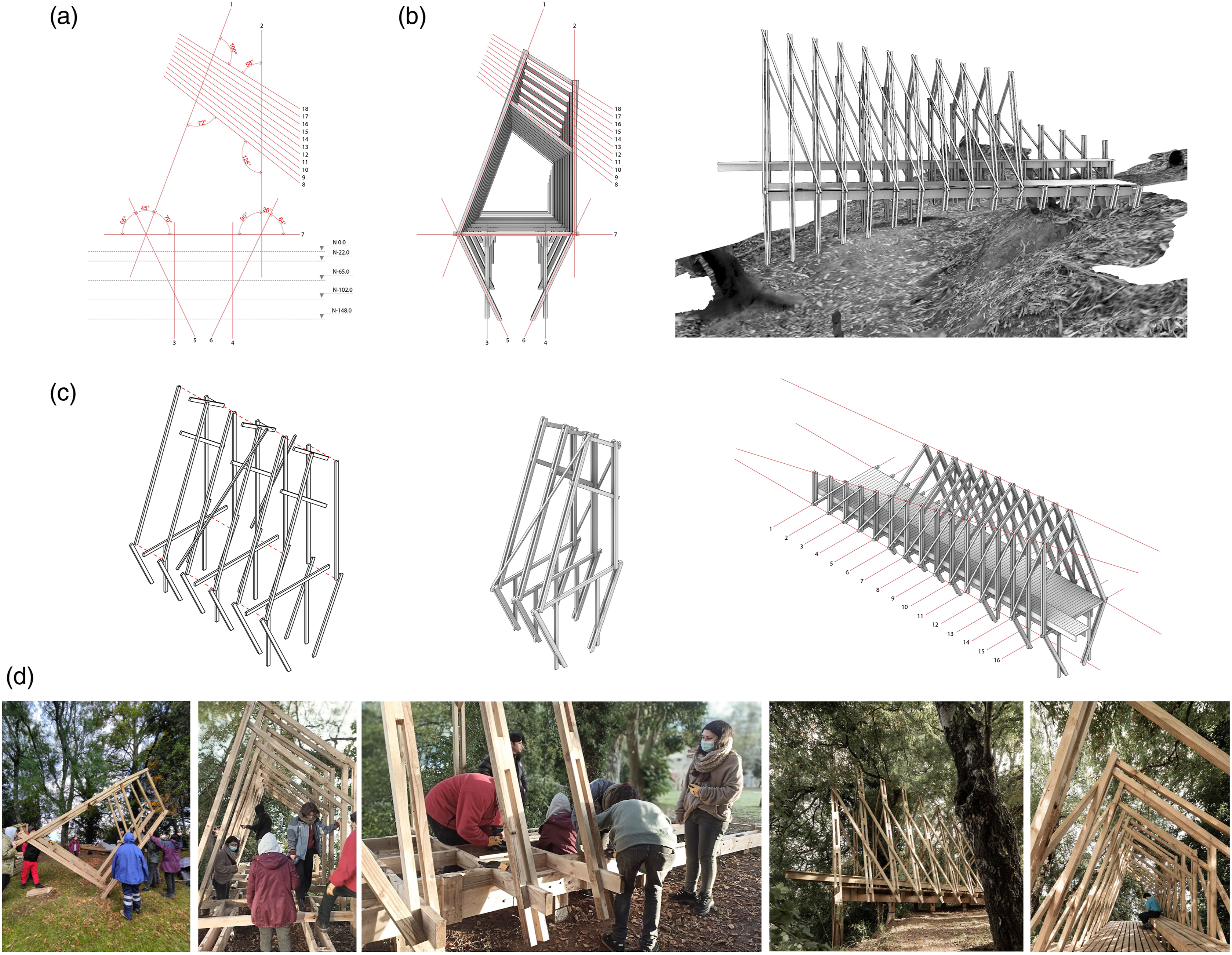
Material Oriented Design (MOD): The material is still timber, but this time in a greater number of variations. These will respond directly to the structural requirements of a pier design (beams, primary structure, secondary structure, etc.).
Fabrication-Based Design (FBD) + Computational Design (CD): The structure had to be articulated by means of a face-to-face connection system. The truss concept is therefore used again to create a habitable interior space. This time, it is not the angular variation that is the priority of this research, but rather the sequence of repetitions. Following this logic, a three-sided fence was established as a basic element. In this way, it would be possible to vary the angle at the upper ends while maintaining the control points of contact with the surface (Figure 10(c)). This simplified the reinforcement system and ensured that the trusses were always in contact with the surface. Each truss sequence allowed the generation of graded angles at the top of the truss. To control the load distribution and structural behaviour, Karamba 3D was integrated into the workflow to achieve optimal behaviour and ease of construction.
Muelle needed two distinct parts to the design. Firstly, a specialist team was responsible for establishing the calculated support points for the pier. The timber used responded directly to create a safe plane to support the pier. Second, and in parallel, was the prefabrication of the pavilion. A total of 102 single piece timber slats were used to construct 11 trusses. Diagonal elements were used to connect the trusses, forming a reciprocal grid.
Once again, knowledge of the material’s properties and design based on the manufacturing possibilities allowed a highly refined control of the result. Muelle could be built without having to manage dozens of items, but rather three main ones: measuring, cutting and screwing (Figure 10(d)).
Discussion
Material
Timber was a relevant material in the pursuit for increase the scale of material approaches made in these workshops. Its accessibility of standardized formats throughout Chile, in addition to its conditions and benefits in terms of lightness and high structural performance, as well as its fasteners with simple elements, were important criteria for testing various manufacturing scales without compromising the use of advanced manufacturing technologies.
For structures with such complexity, Karamba seems sufficient for calculations on a smaller scale, allowing us to safely anticipate possible natural problems of changing stresses. However, in future work, as we face larger sizes and geometric complexities, we believe it is necessary to integrate a professional into the design workflow.
Students basic construction knowledge helps them foresee possibilities and limitations in their projects and the final installation, shown by their autonomy in construction tasks. This facilitates the absorption of learned skills. Yet, as workshop complexity grows, more in-depth guidance at each process stage will become necessary.
After ten completed pavilions, and specifically after analysing these three cases, it is possible to draw conclusions about the scalability potential of wood. Two concrete examples are presented here, firstly the adaptability and iterative capacity of the designed nodes. The first case presents a simple face-to-face node developed on an axis and a base rotation plane. The second case is solved with the same face-to-face node system, but it is developed on 3 growth axes and two rotation planes. Finally, the last case, solves its growth from the same node, but with independent nodes according to its structural function.
This last characteristic, the structural stresses, is also the second proof of the scalability of wood. The first and second cases are self-supporting structures, which means that they depend exclusively on the mechanical properties of the wood to resist the stresses applied, furthermore the third case, the pier, integrates structural stresses combined with live loads derived from traffic and the weight of people.
Method
By reducing complexity and limiting the range of possible interconnect combinations, this approach provides a cost-effective alternative to manufacturing that, despite the computational design involved, still relies on analogue material processing techniques, bridging the physical and digital realms in contexts of intensive academic experiences. 14
The combinatorial capability of MOD and FBD enables a synergy where the design is informed by both the material potential and the fabrication process. This can lead to more robust, efficient and potentially innovative solutions. As seen in the cases, the design process may start with a MOD approach, but as it progresses, the limitations or capabilities of the FBD manufacturing process may feedback and influence design decisions. As new fabrication techniques emerge or new material properties are discovered, the combination of MOD, FBD and CD allows the workshop to adapt and evolve.
The ability to combine variables and software that the appropriation methodology analysed here presents can be seen through the evolution of its cases. From Discrete Structure I, a formal exploration structure designed on a generic site, to the Muelle Pavilion, a controlled design with structural analysis, site information (LiDar) and a functional use of the pavilion, highlights the replicability potential of the method, which can operate under different parameters and be adapted without compromising its constructability. This trajectory demonstrates that while the methodology retains its central focus on traditional manufacturing processes and timber as the predominant material, it is also adaptable to existing manufacturing tools and technologies, particularly in environments where advanced manufacturing tools are not readily available. 17 It is therefore possible to build on Gershenfeld’s argument in this article about digital tools in relation to traditional tools.
More research is needed to detail and enhance the methodology, yet it serves as an important foundation. Using common building systems and traditional techniques opens a vast area for exploration. These exercises in regions lacking digital tools and guidance highlight the methods potential for contextual adaptation.
Workshop
The collaboration with different Schools of Architecture in the country opened up this problem related to fabrication methods. ¿How do you teach digital design tools without having digital fabrication tools? Here, local possibilities and contextual realities are active variables in addressing workflows in technological processes. 18 It is not only about the use of new tools but also about the relevance and capacity to appropriate such developments. Consequently, innovation in contexts of technological deprivation can be understood as a novel re-reading of an existing context. 16
A key lesson from the work undertaken is the need to strike a harmonious balance between tradition and innovation. The incorporation of digital design methods into the academic framework should not overshadow the value of traditional methods of design and construction, but should be seen as a complementary tool that, when progressively incorporated, complements and enhances traditional practices. 19
A satisfying observation is the recognition that although the participating students started from a basic user level, by the end of the workshop they had acquired the necessary skills to use digital design tools with a certain degree of autonomy. This improvement in their skills underlines the potential of these intensive workshops to accelerate the acquisition of competences during the undergraduate phase.
Future editions could improve by reconsidering the workshop duration since the extensive information covering digital tools, model fabrication, and pavilion construction can overwhelm participants. Extending the workshop over several weeks may allow students more time to absorb the material and engage more deeply in the early design stages of the final pavilions.
Despite students basic knowledge of timber construction, many have not built 1:1 prototypes because construction systems are usually associated with building rather than exploratory methods like in the workshop. Therefore, this activity provides benefits in understanding design methodologies and digital fabrication, as well as in reviving hands-on construction as a learning approach.
Footnotes
Acknowledgments
The authors would like to thank the School of Architecture of the Universidad Austral of Valdivia for their collaboration, especially the director Cristian Valderrama. To the third year students of the Universidad Austral, participants of these three instances, who made the construction of these pavilions possible. To our research and design team: Gonzalo Vegas, Matías Correa, Valentina Cabrera, Constanza Grenett and Amaya Glaría. And special thanks to Pablo C Herrera, for always encouraging us to disseminate our work.
Declaration of conflicting interests
The author(s) declared no potential conflicts of interest with respect to the research, authorship, and/or publication of this article.
Funding
The author(s) disclosed receipt of the following financial support for the research, authorship, and/or publication of this article: This work was supported by the Fondart, National Fund for the Arts, Cultures and Heritage (This research has been funded by Fondart, National Fund for the Arts, Cultures and Heritage. Mincap, Chile).