
Abstract
A form-finding technique based on the deformation of plastic sheets by the action of gravity and temperature increase is proposed, allowing the exploration of complex geometries to support form-giving processes within architecture projects, both by students and practitioners. Using an analog and computational approach, the ideal material for the technique was selected from a multifactorial experiment. Semi-structured analog experimentation was carried out based on inputs, rules, and outputs previously identified, and the resulting models were morphologically analyzed, to later translate the components of the analog experimentation into a computational algorithm to carry out computational experimentation. The technique can be used as a generator of novel forms possessing adequate transformational qualities. Finally, potential applications of the technique and avenues for future research are presented.
Keywords
Introduction
Tools and strategies have been developed to enhance the creative generation of architectural forms among students and to invigorate the form-giving processes within projects undertaken by expert architects. These strategies encompass activities such as precedent searches, the creation of mood boards, and the utilization of form-finding techniques. Form-finding techniques involve the designer’s interaction with three fundamental elements: (i) the technical properties of the material, which include mechanical, chemical, magnetic, and acoustic properties 1 ; (ii) the geometric properties, such as size, proportion, surface, texture, and symmetry, possessed by both the material and the form sought; and (iii) rule-based processes, that is, the manual or automatic interaction of the two previous elements from algorithms of different complexity.2–4
Rules consist of an input, a process of controlled manipulation of variables, and an output. Likewise, rules are based on physical phenomena that usually allow finding forms that, due to self-organization, are like geometric patterns present in nature. 5 Self-organization is an automatic procedure that is mediated by the designer’s manual or computational actions, which allows physical phenomena, such as gravity and electromagnetism, to interact in the triad: “technical material properties,” “geometrical properties,” and “rule-based processes.” The greater the self-organization, the greater the possibility of generating forms like geometric patterns found in nature, and the greater the likelihood that they will become a support or additional aid for application in architecture.
Now, analog form-finding can help to generate ideas in this phase of the design process, providing cognitive and technical tools to alter the passive state of the designer,6,7 visualize early on design proposals, 8 generate forms with geometric characteristics similar to those found in living and inert nature, 5 increase the size of the morphological vocabulary of each designer, 9 and check as early as possible technical and structural properties of the project. 10
Furthermore, it is usual for the analog form-finding to precede the computational or digital ones. Although both approaches are conducive to the rapid exploration of forms11,12 and the development of complex geometries that would otherwise be difficult to find, 13 the two have different strengths. The computational approach, for example, allows for a higher level of automation, accuracy, and proximity to digital fabrication, 14 but the analog possesses strengths at the cognitive level that make it suitable for use as a creative resource in the form-giving phase. Likewise, the analog approach allows transit through areas of the design space, such as the generation of highly complex forms, which, to make them digitally, would require the use of complex algorithms, programming, and a high investment in time.
Deformation of plastic sheets
Different form-finding techniques are present in the scientific literature. For example, Otto and Rasch, 5 Gaß, 15 and Patiño and Maya 8 present the most extensive catalogs in the number of techniques. In addition, there are reviews of specific techniques: the studies on membranes and minimal surfaces by Bletzinger 16 ; tensegrity structures by Tibert and Pellegrino 17 ; bending-active structures by Lienhard et al. 18 ; reciprocal structures by Thönnissen 19 ; and folding structures by Lebée. 20 In the context of plastic sheets and heat, Chen et al. 21 introduce a form-finding technique based on thermoforming. This method involves heating thin plastic sheets until they reach a malleable state, allowing an industrial robot to subsequently manipulate them and generate three-dimensional shapes.
But from what has been traced, only Bradley and Gohnert 22 present experiments on the deformation of plastic sheets due to the influence of temperature and gravity. They use hanging models of previously heated plastic sheets (polymethyl methacrylate) to explain the structural behavior of the Mapungubwe shells, a building located in South Africa. They make two types of models, the first with a square sheet attached to its four corners, and the second with a rectangle attached to two of its opposite sides. In both cases, it is observed the generation of catenary curves by the action of gravity and the increasing temperature, which, being inverted as shells, efficiently distribute the loads that are perpendicular to the ground.
This type of deformation occurs because thermoplastic polymers, such as polymethyl methacrylate or polystyrene, change their behavior as the temperature or the experiment time scale increases. At low temperatures, polystyrene is expected to behave similarly to glass, with a high Young’s modulus, that is, in a state of stiffness associated with small displacements of the molecules. In contrast, at high temperatures, polystyrene is expected to behave viscous, with a low Young’s modulus, that is, rubber-like elastic deformations due to the flexibility of the molecular chains. 23
In practice, as the temperature of the sheet is increased, there are several transitions between the stiff and viscous state, but there is a primary transition commonly called the Glassy Transition that involves a large change in Young’s modulus. The temperature that produces it is called tg (Glass-transition temperature). The change in viscosity by temperature can be explained by equation (1), where n is the viscosity, aT is the temperature change factor, nt is the polymer temperature, and ntg is the glass transition temperature
23
:

Similarly, the relationship of Young’s modulus with the relaxation time of viscoelastic behavior can be seen in equation (2), where t is the time, n is the viscosity, and E is Young’s modulus
23
:

Objective
Therefore, the objective of this article is to present a form-finding technique based on the deformation of plastic sheets by the action of gravity and the increase of temperature, which allows a structural exploration but, above all, enables a creative exploration of complex geometries. This technique can support form-giving processes within design and architecture projects, facilitating the understanding of the process, accelerating the form-finding process, 14 and providing clarity to control the inputs and outputs of the procedures. The development of these types of techniques prevents costly revisions in the design process and reduces the time required for project execution.26–29.
The technique combines analog and computational approaches to form-finding. This allows, on the one hand, to understand experientially the interrelation of “the technical properties of the material,” “the geometrical properties,” and “the process based on temperature and gravity,” to facilitate the programming of the computational algorithm. And, on the other hand, to broaden the understanding of the creative tools that can support the design process. As mentioned above, the external representation, in this case, the analog mock-ups and digital drawings, is directly related to creativity to the extent that it has the function of cognitively assisting the design process, that is, it releases the memory and attention load so that the designer can think easily. 30 This makes, among other things, that mental images and visual representations relate in a reflective dialogue, 31 enabling the generation of a broad set of representations or design proposals. 32
Methods
For the development of the technique, the following methodological route was followed: (i) selection of the thermoplastic polymer that allowed heat deformation; (ii) design of the semi-structured experimentation of the technique; (iii) analog generation of forms resulting from the technique; (iv) analysis of the analog deformation of the forms; (v) design of the prescription-based algorithm to emulate the results of the technique; and (vii) analysis of potential applications.
Selection of the thermoplastic polymer
To identify the polymeric material with the best behavior to deformation by a heat source, a multifactorial design experiment was developed with three laminar materials that could be deformed with conventional thermoforming equipment of local construction (no brand name), as shown in Figure 1. The experiment included as fixed variables the thickness of 2 mm, the temperature of 140°C, and the characteristics of the heat source (Figure 1). The independent variables were the material, the type of constraint, and the time since the sheet reached 140°C. Noise factors such as climate and possible equipment overheating were decreased by randomly sampling the experiments. Finally, the dependent variables or response variables that were analyzed to select the material were strain height (H) and undesired effects on geometry. (a) Heat source and device location. (b) Device securing the plastic sheet. 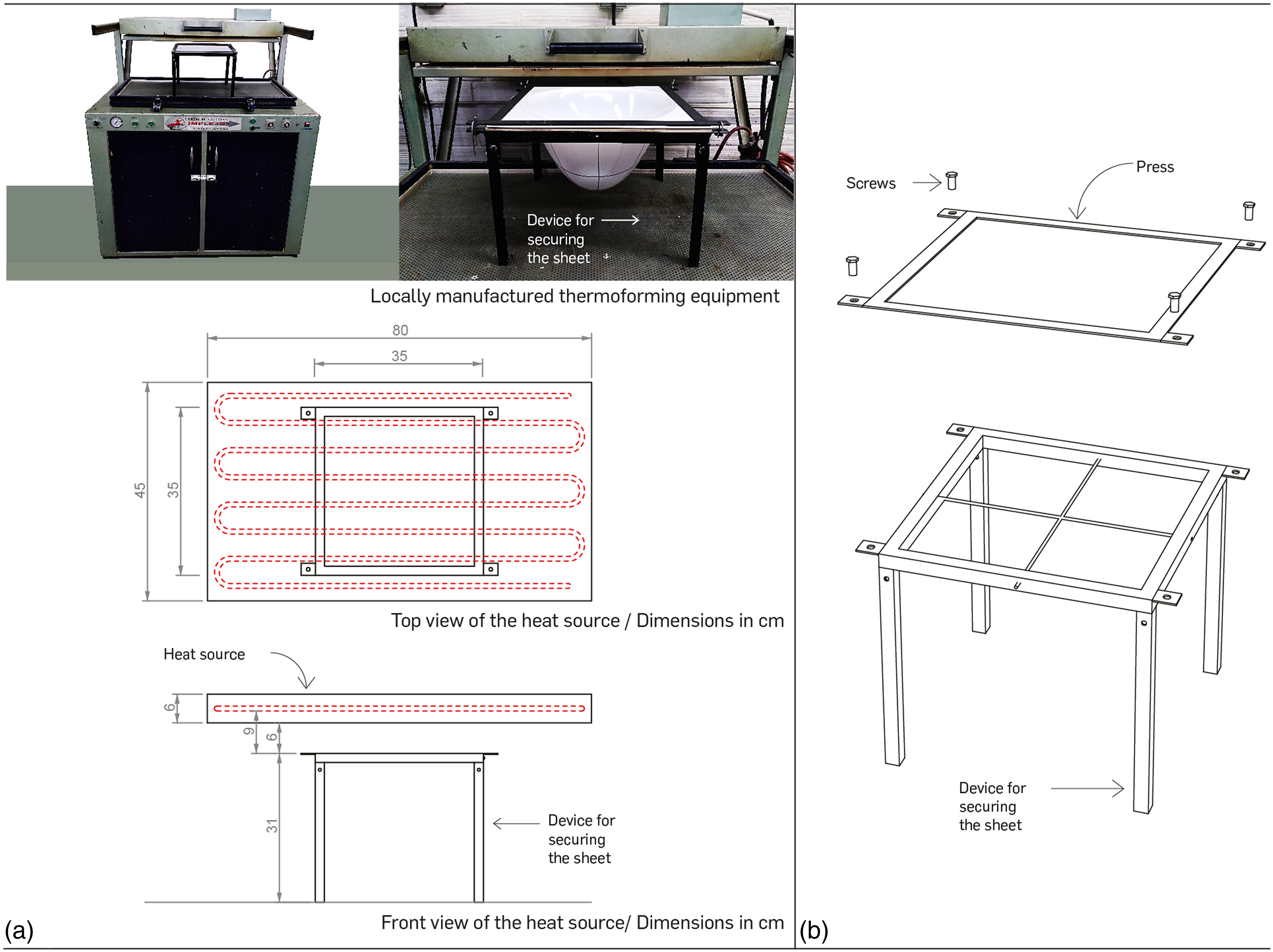
The three materials tested were polystyrene glass, polystyrene, and polymethyl methacrylate. There were two types of restriction: without internal support or with a cross support in the middle of the sheet. The times to perform the experiments were 45 and 75 s. The resistance of the equipment can reach 290°C; therefore, the time of the experiments was taken from when the sheet reached 140°C in its center. This was the base temperature, considering the thermoforming temperature of these polymers: in a range between 135°C and 170°C for polymethyl methacrylate and 140°C and 170°C for polystyrene. 33 It should be noted that, due to the irregularity of the sheet thicknesses and the type of heat source, in this case, an “S”-shaped upper heating element, the temperature in all areas of the sheet is uneven. In addition, the equipment does not allow the temperature to stabilize; therefore, after reaching 140°C, the temperature continues to rise in relation to the time the experiment would last.
The tools used for the execution of the experiment were the following: a. Digital infrared thermometer. b. Locally manufactured thermoforming equipment (Figure 1(a)). c. Device for securing the plastic sheet (Figure 1(b)).
Design of the semi-structured experimentation of the technique
A semi-structured experimentation scheme was established with the promising variables that emerged in the material selection. Semi-structured is understood here as the theoretical proposal of the possible relationships between all the independent variables but the empirical execution of only some of the relationships. For this, six independent variables were defined: (A) Time, (B) Type of sheet, (C) Contour, (D) Support, (E) Court, and (F) Group, each having its respective levels.
This means, for example, that for an experiment with six independent variables, each with an average of seven levels, 276.000 combinations are possible (6⁷), which would also have to be evaluated quantitatively with the dependent variables. However, since it is not in the interest of the procedure to find the best values of the variable (i.e., the best forms) that influence the results to the greatest degree, it was decided to establish a qualitative exploration approach to run only those combinations that showed some possibility of significantly varying the results.
Analog generation of forms resulting from the technique
The interaction between the six independent variables and their respective levels occurred to generate novel shapes with complex geometries. This was done to expand the exploration space with the available resources, that is, to increase the possibility of finding results different from each other in the generation of the form, with little investment of time and material inputs. From this qualitative approach, each time a variable combination was started, it was based on the results of the previous combination.
Analysis of the analog deformation of the forms
To analyze the forms, tests were conducted to measure the deformation of the axes and the thickness of predetermined models. For this purpose, the same tools used for selecting the thermoplastic polymer were employed, along with a Mitutoyo Absolute model digital calibrator. Subsequently, some analog models were scanned using a GOM scanner, ATOS Core 200 model, with GOM Inspect 2018 software. Finally, the stresses involved in the deformation were graphed, and the geometries were analyzed using Rhinoceros 7 software.
Design the prescription-based algorithm
The Rhinoceros 7 environment was used for the algorithm design, specifically Grasshopper Software (with GhPhyton Script and Kangaroo 2) for developing a logic that would emulate the outcome of heat and gravity-induced deformation in plastic films. For this purpose, four algorithms were developed to geometrically replicate the deformation of two experiments without deformations and two with perforations. Their logic was developed in relation to the stresses affecting the material due to temperature, gravity, and independent variables: time, sheet, outline, and support. Subsequently, common points were analyzed, and a single logic or deformation sequence was developed.
Analysis of the computational emulation
Using Grasshopper and Rhinoceros Software again, graphical diagrams were created to depict the outcomes of the algorithms and the sequences of deformations.
Analysis of potential applications
Finally, a framework is proposed for envisioning possibilities for applying the process and the resulting objects through the study of nine design and architecture cases. Firstly, some results of the technique were associated geometrically with design and architecture projects. Secondly, the possible materials and manufacturing processes were analyzed using the manufacturing process and material selection methods proposed by Ashby and Johnson 34 : (i) Synthesis: Materials that conform to the overall design constraints and requirements are sought without necessarily examining each property in detail. Materials that have proven effective in similar applications or that align with intuition and experience are considered; (ii) Similarity: This approach identifies materials previously used in similar or comparable designs. If a material has performed well in a similar application, it may also be suitable for the new application; (iii) Shaping profiles: Families of shaping processes related to material, shape, required size, precision, and surface finish.
Results and discussion
Thermoplastic polymer selection
As shown in Figure 2, 12 models were made in random order, where material, type of restriction, and time were interleaved. In the models with the polystyrene glass, different undesired effects were present, such as warped geometries and discontinuous curvatures, which, together with the deformation height of up to 16.6 cm without restrictions, caused visible fractures. In the models with polystyrene, the material deformed continuously without generating visible defects; without restrictions, it reached a larger height than the other two materials: 20.2 cm. Experiment to select the material for the technique. 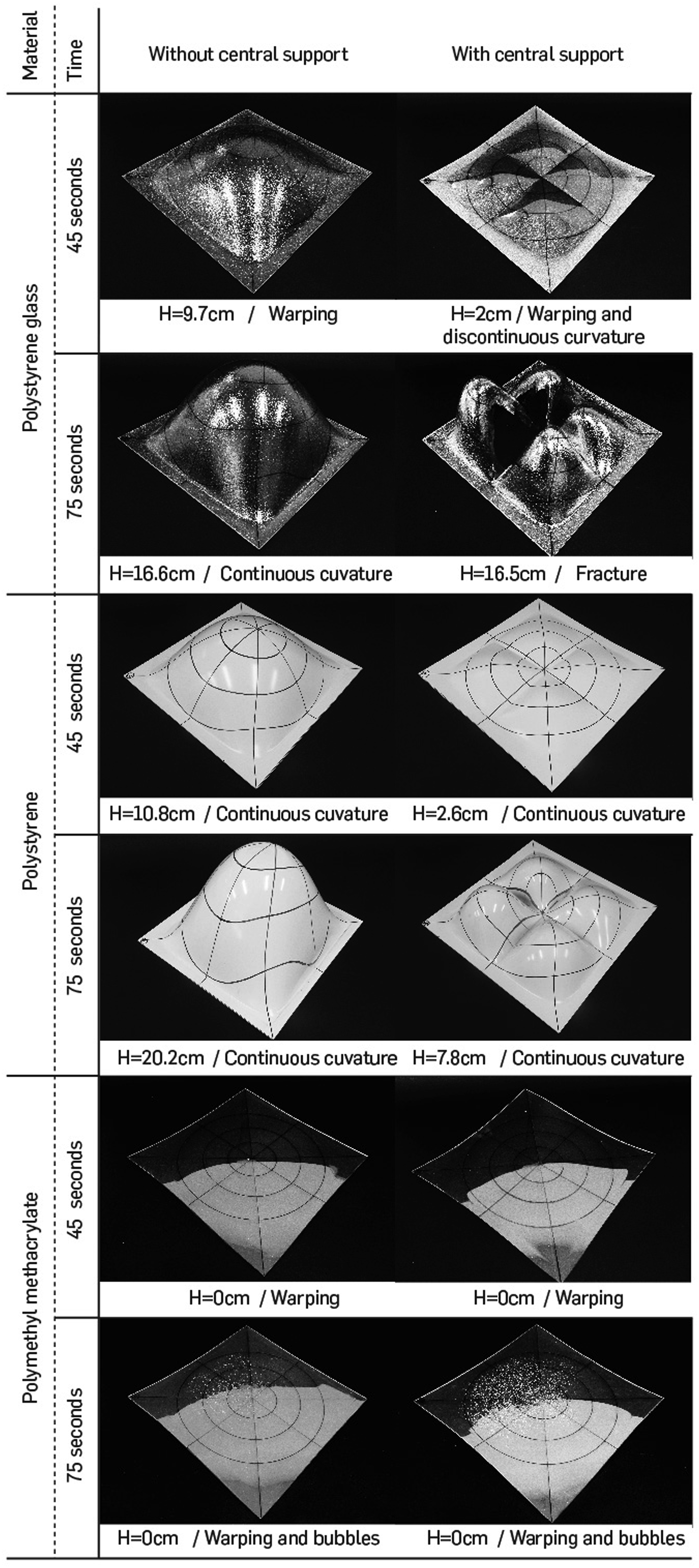
Finally, in the models with polymethyl methacrylate, the material reached a viscous state but was not overcome by gravity. After 70 s, the material loses physical stability and internal bubbles are generated. The bubble defect may be due to irregularities in the thickness of the film, considerable temperature differences in the different zones, or the presence of high humidity. In experiments such as those of Bradley and Gohnert, 22 a heat source is possibly needed on both sides of the foil. In conclusion, the polystyrene sheet was selected because of the material’s heat behavior, continuity of geometry, and its property of reaching higher heights than the other materials without fracturing.
Design of the semi-structured experimentation of the technique
Figure 3 shows the experimental scheme, with a dotted line example of the combination of the independent variables for a particular result, shown at the bottom of the figure. Likewise, the use of the polystyrene sheet support shown in Figure 1 is graphically explained. The independent variables are then (A) Time, (B) Type of sheet, (C) Outline, (D) Support, (E) Cutting, and (F) Group. Graph of the semi-structured experimentation process. 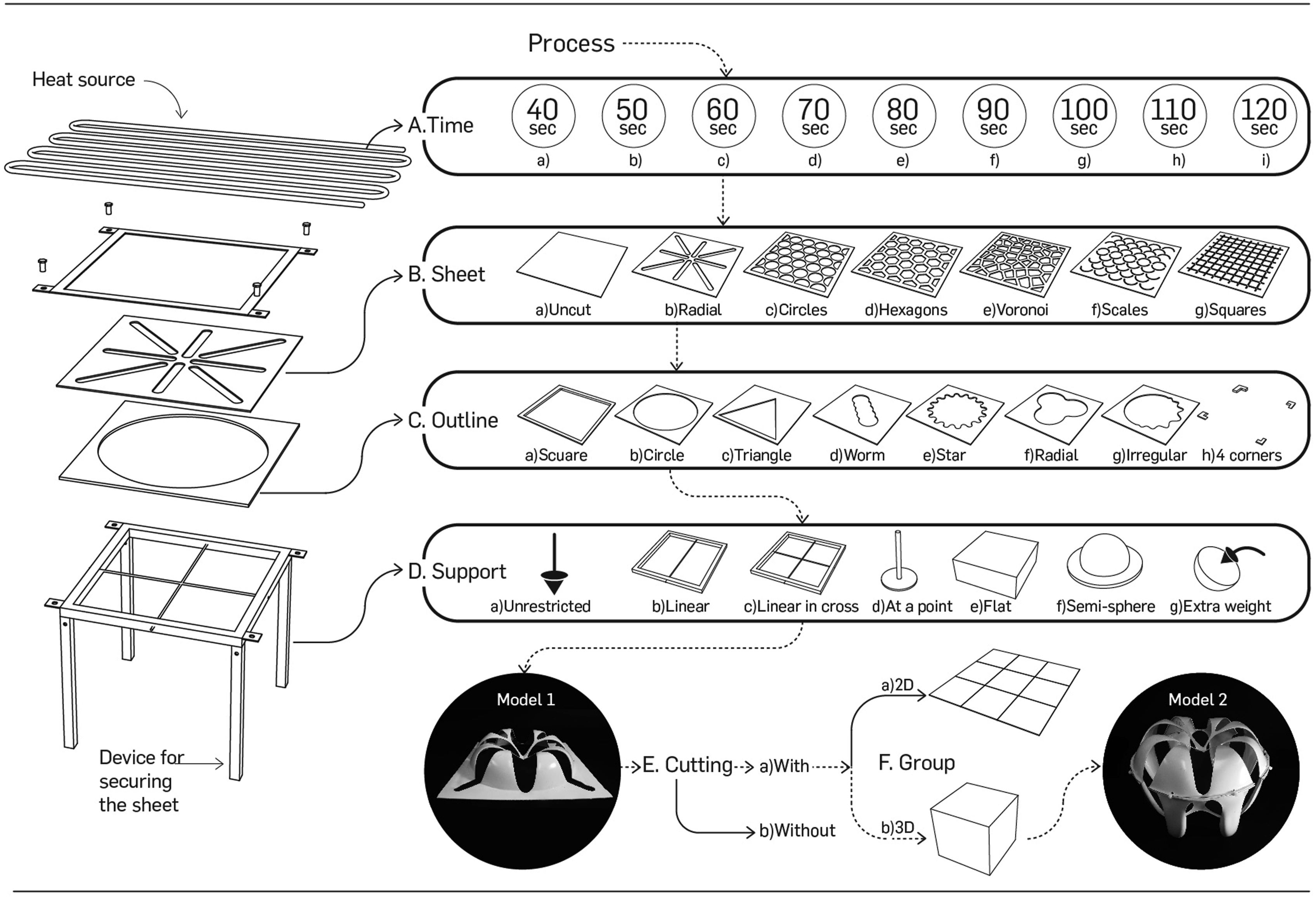
Two models resulting from the technique are exemplified in Figure 3. Model 1 is obtained from the following combination: Ac + Bb + Cb + Dc. This means that the following specifications were used: a. It was heated for 60 s after it reached 140°C. b. A 2 mm polystyrene sheet with a radial cut was used. c. A circular outline was used to limit the deformation. d. A linear cross support was used to restrict deformation as well.
For model 2, a cut is made following the geometry resulting from the deformation of the previous model and it is grouped with a similar geometry so that it is configured as a solid or three-dimensional volume. That is to say, that the combination Ea and Fb is added to the combination Ea and Fb.
Analog form generation
Figure 4 shows the results of the semi-structured experimentation scheme. The variable (E), Cutting, was defined to change the perception of the result, to change from a surface to a three-dimensional solid, which, although geometrically only a flat area was subtracted, allows perceiving the object differently. In practice, the models were cut by the deformation line established by the variable (C), Outline, or by the union of this line with the geometry of the perforations of the variable (B), Sheet. In the variable (F), Group, whose models can be seen in Figure 4 in results 17 to 24, the use of symmetries and repetitions for clustering in a plane, that is, 2D group, and for grouping with symmetries and repetitions in a three-dimensional space, that is, 3D group. Results of the semi-structured experimentation. 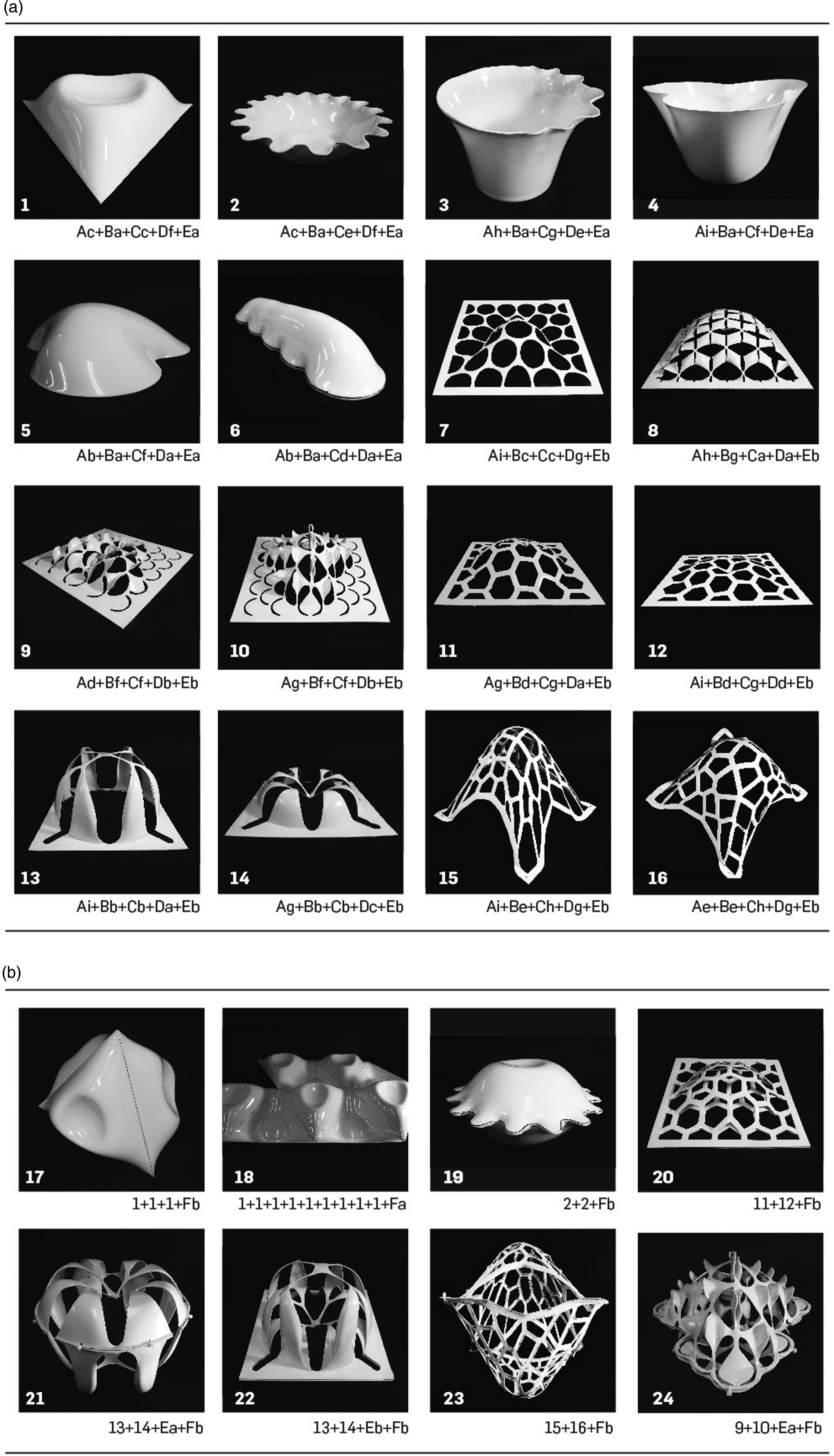
For example, in result number 17 in Figure 4, three models of result number 1 are used to be grouped three-dimensionally as a tetrahedron, that is, 1 + 1+1 + 1 + Fb. Similarly, in result number 18, nine models of result number 1 are used to generate a grouping in a plane and occupy a two-dimensional space, that is, 1 + 1+1 + 1 + 1 + 1+1 + 1+1 + 1 + 1 + 1+1 + 1 + 1 + Fa.
Concerning the constituent elements of form-finding, “technical properties of the material,” “geometrical properties,” and “rule-based procedures,” the plastic property of the material that allows it to deform uniformly by heat allows one to find forms of continuous curvatures, with a high geometric variety, that is, the results are geometrically different from each other, demonstrating the creative possibilities of the technique. On the other hand, the procedure established in the experimentation allows us to visualize (i) Input (plastic sheet, heat, and restrictions); (ii) Process or rule (gravity, heat deformation, and plastic behavior); (iii) Output (doubly curved surfaces); (iv) Variables (time, sheet type, outline type, support type, cutting, and group); and (v) Constants (temperature, sheet thickness, and polymer type).
Analog deformation analysis
To control the deformation process caused by changes in viscoelastic behavior, four deformation tests were performed to demonstrate the geometric changes of the technique. In the first two tests, sheets without perforations were used, and in the last two tests, perforated sheets were used. The same 2 mm polystyrene sheet, the same heat source, and the same period were used for the tests: 80 s after reaching 140°C in the center.
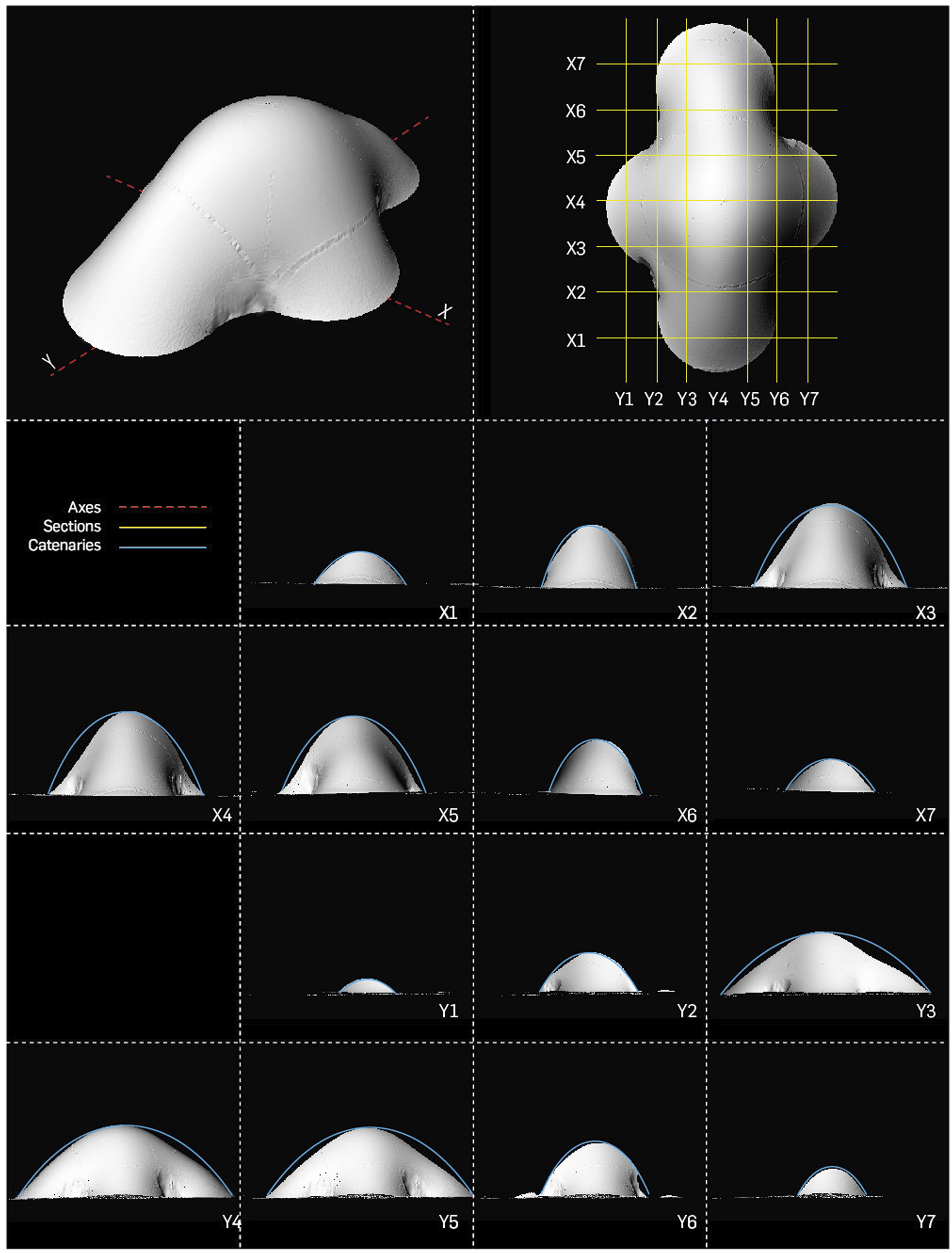
Figure 5 shows the circular deformation test, in which a mold with a die-cut circle was used, trying to recreate a homogeneous process. The figure shows the sheet with three zones and eight axes of analysis without the effect of the temperature increase and the same zones and axes in the deformed model. By measuring the axes, the closer the zone is to the center, the smaller the deformation, and the farther the zone moves away from the center, the greater the deformation, deforming up to 110.2% of its initial length. On the contrary, the thickness of the polystyrene zones decreases the further away they are from the center of the sheet, decreasing the thickness up to −59.09%. Circular deformation test. 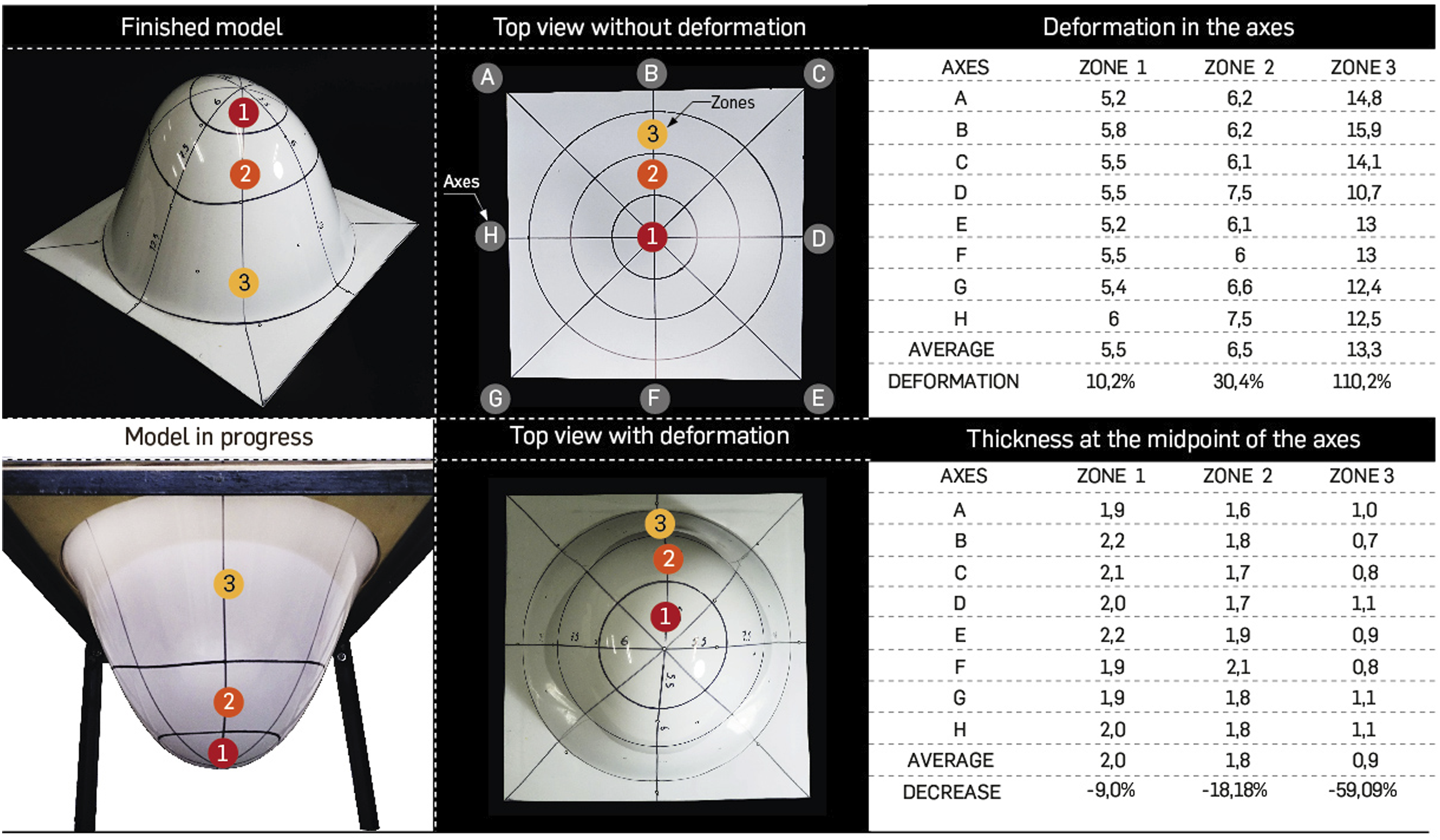
Figure 6 shows the irregular deformation test; in this test, a mold with an irregular die was used to determine the similarities and differences with the circular deformation test. In contrast to the previous test, in this one, zone 1, closer to the center, deformed more than the other two zones. Zone 3 was outside the area of influence of gravity, but this zone showed only up to 20.5% deformation. This is because there are points within the same zone that are far away from the support zone, and others that are very close, causing the deformation to adapt to this change in stresses. Likewise, there are changes in the thicknesses, but they do not exceed −22.7%, well below the circular test. This is because there is less weight that can be influenced by gravity. Irregular deformation test. 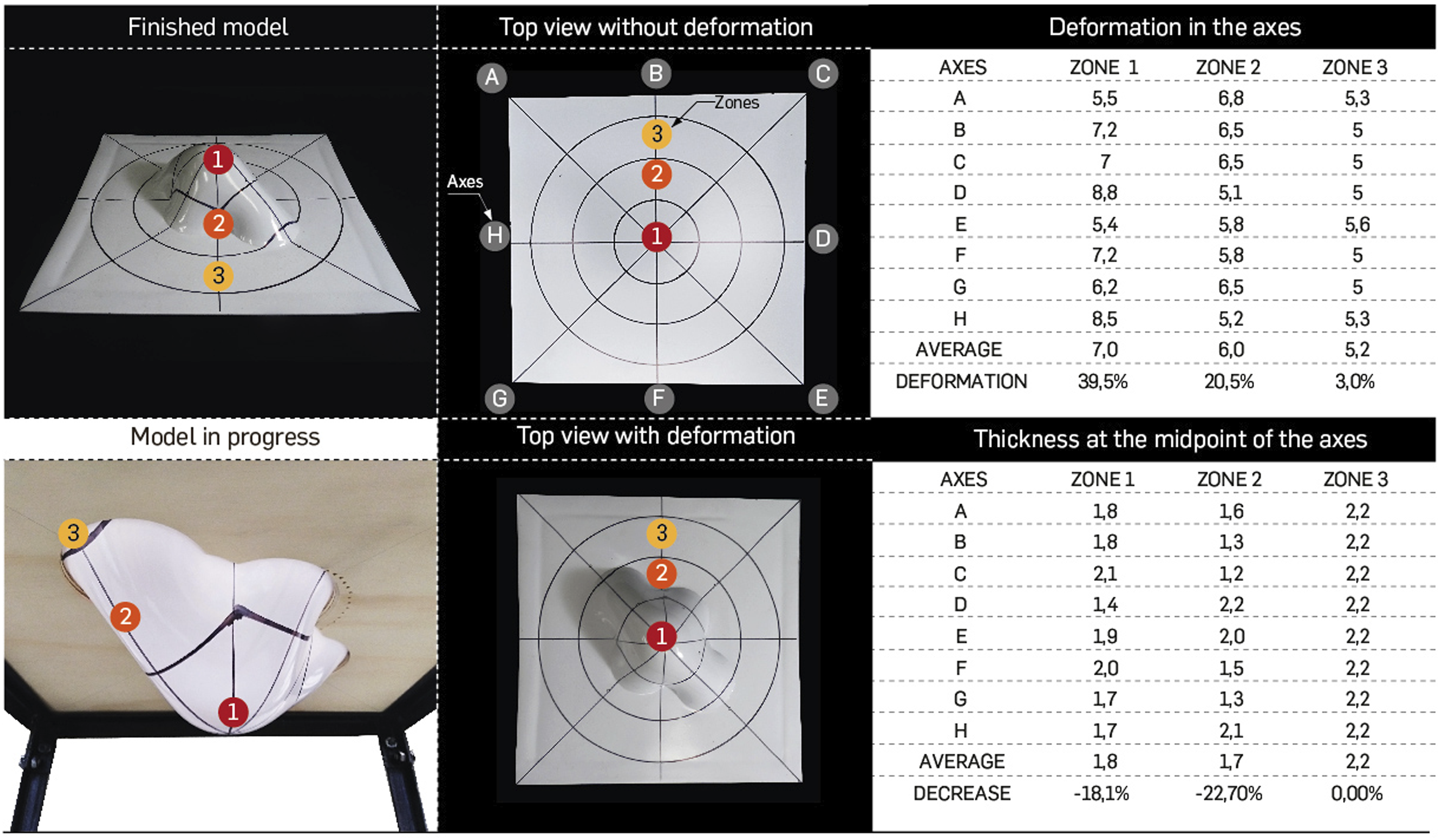
In Figure 7, this deformation process can be better understood. The sheet’s first point, “C,” influenced by gravity, is the farthest point from the bearing surface. On the support surface, an anchorage is generated due to the die-cut wood and a press-type metal sheet, which can be seen in Figures 1 and 3; this press holds the polystyrene sheet from the top. In this anchorage, N, as the normal stress, is perpendicular to the support surface. The larger the surface outside the support area, the greater the weight, and the greater the stress. Physical analysis of stresses and the influence of gravity, in a plastic sheet with heat supply at the top and anchoring in the flat area. 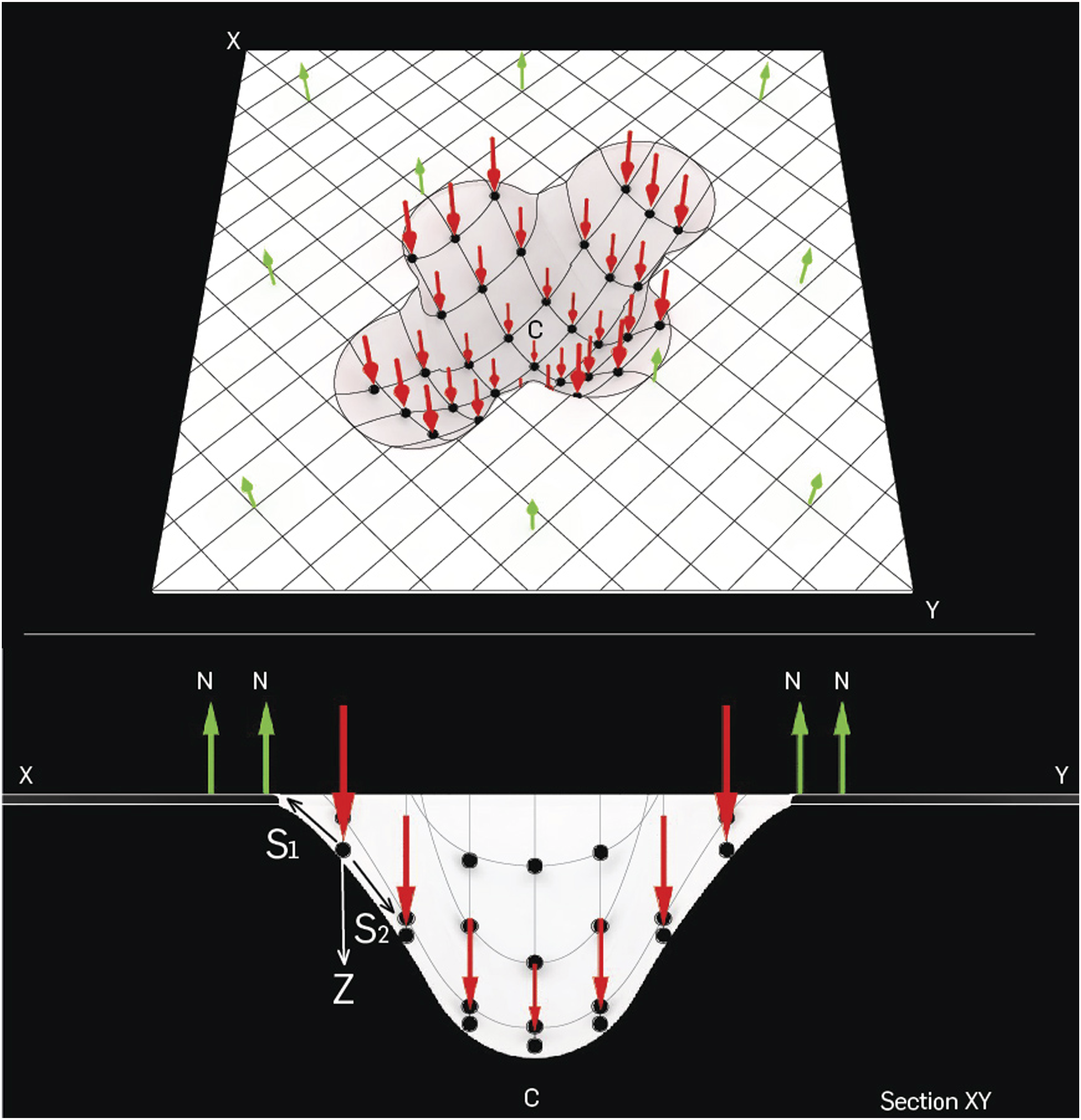
The stress of each point results of the stress of gravity Z, the stress of the upper anchorage S1, and the stress of the weight of the lower material S2. The higher the point is located, that is, the closer it is to the bearing surface, the greater the stress S2.
In a form like that of Figure 6, the stresses are very heterogeneous, which makes their analysis more complex, but in a form like that of Figure 5, the stresses are more homogeneous and regular, making the behavior more easily predictable.
After understanding the material behavior with increasing temperature and its changes in stiffness, a geometrical analysis was carried out to look for structural possibilities. Theoretically, plastic sheets, elastic fabrics, or meshes pulled by gravity generate catenary curves. To empirically test this proposition, the two previous deformation tests were scanned, and the surfaces were cut with Rhinoceros 7 software. Employing the Grasshopper plugin, which has programmed the algorithm that represents the homogeneous gravity force on any line, the catenary curves were modeled between the two points that are extremes of the cuts. The length given to the catenary was the closest to the curve of each cut. Figures 8 and 9 show the cuts with the graphical relationship of the catenary. Geometric analysis of the circular deformation test. Geometric analysis of the irregular deformation test. 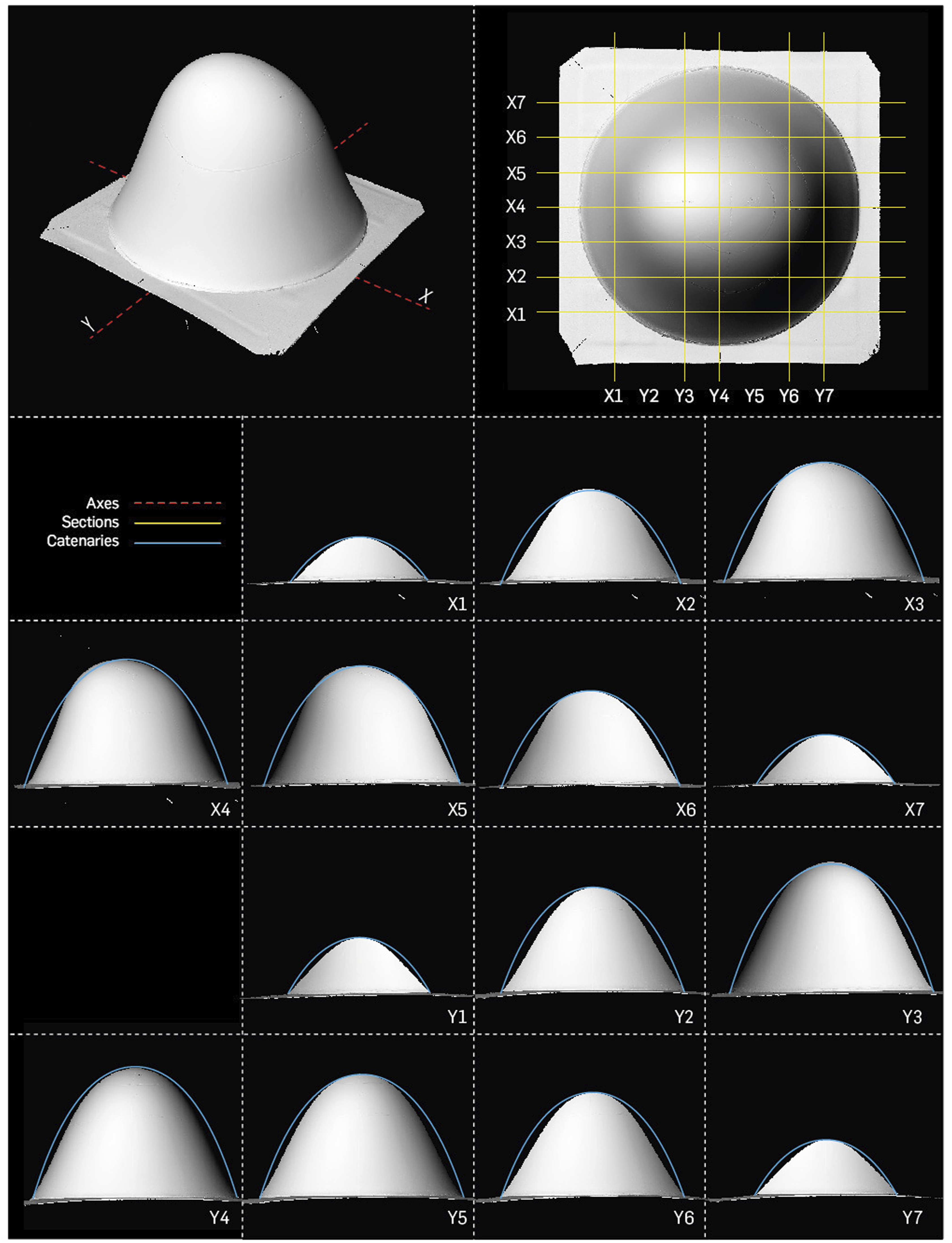
In both cases, the curves that originated are not exactly catenary, that is, they do not have the same structural behavior as the catenary when it is inverted and subjected to a compressive force. If the sections of the technique were catenary curves, the surface generated could be geometrically described as a double positive curvature; on the contrary, the analysis shows that the surface generated is a double-negative curvature caused by the relationship described above, between the strength of the stresses and the height of the points (Figure 10). Geometric analysis of the double-negative curvature. 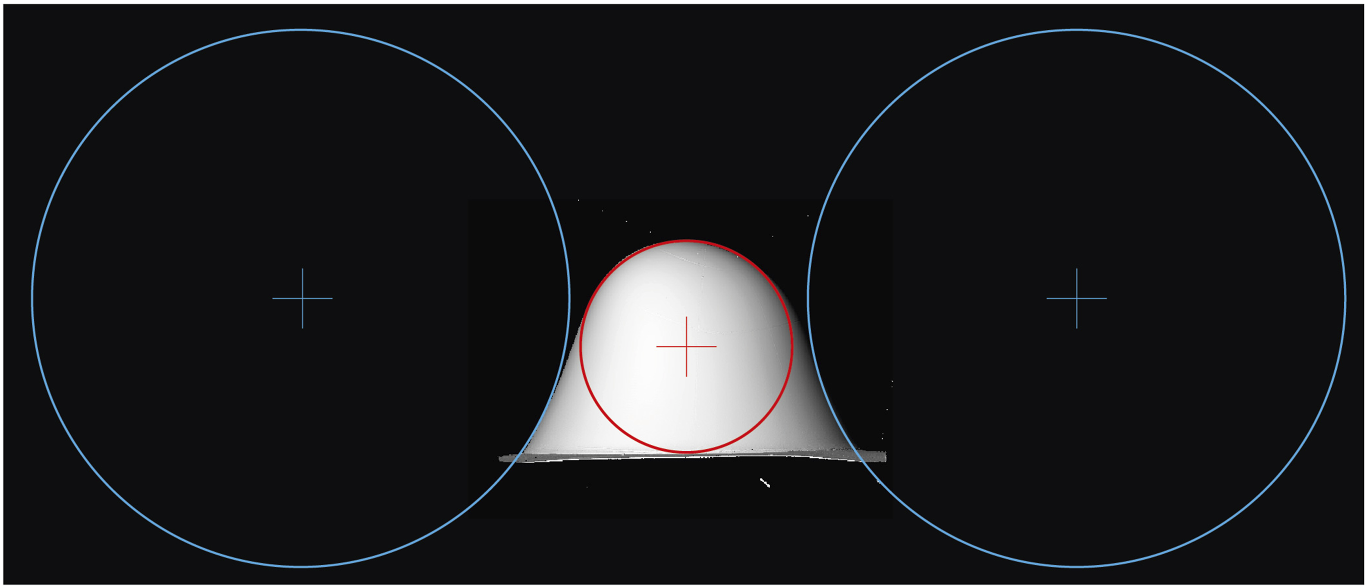
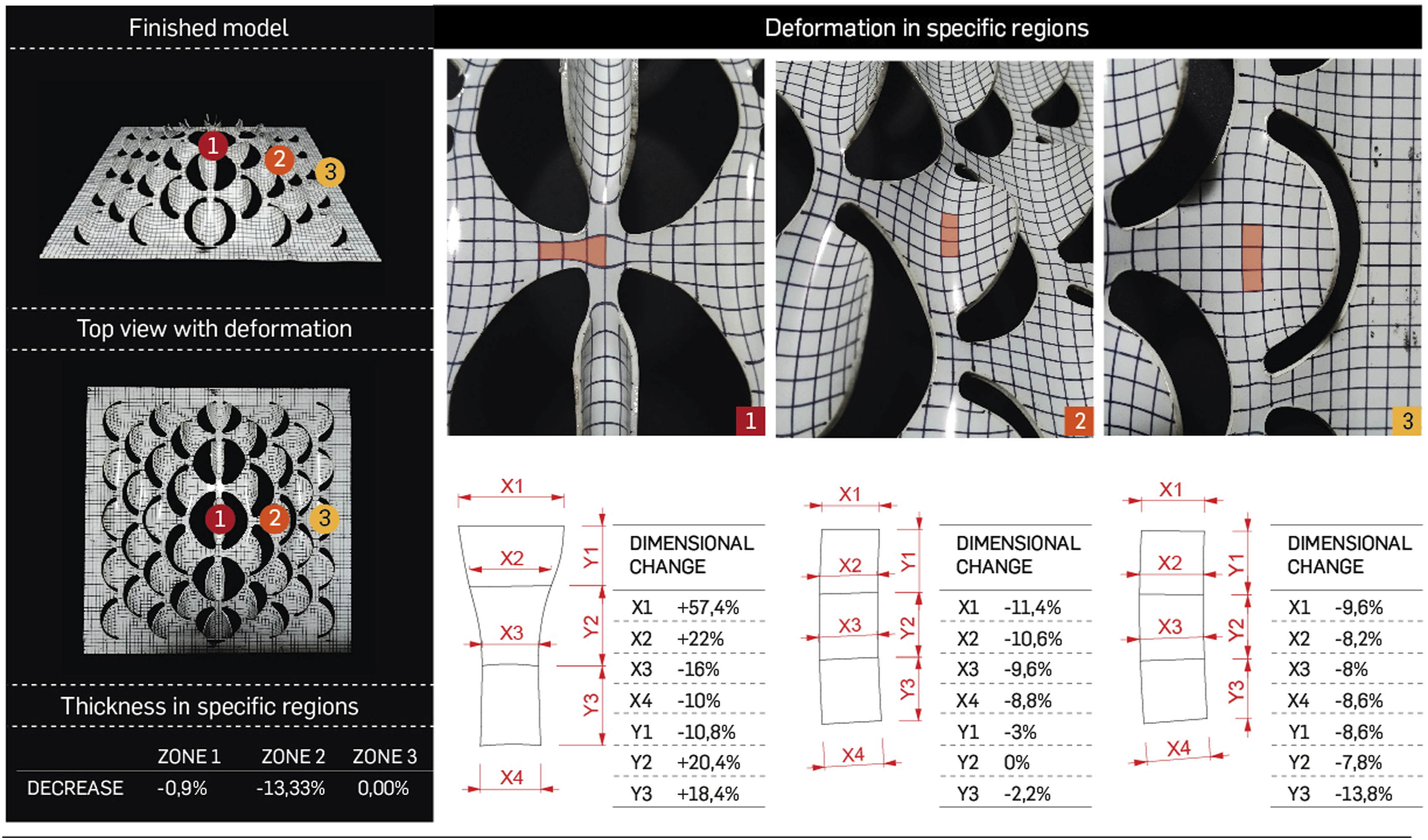
Additionally, to gain a comprehensive understanding of the material’s behavior, Figures 11 and 12 present the geometric and deformation analysis of the material from two additional tests using polystyrene sheets with different perforations. In this case, radial axes were not used due to the geometry of the perforations not allowing for accurate readings. Instead, a 5 mm × 5 mm grid was drawn, and specific study areas were identified. Geometric analysis of hexagonal grid. Geometric analysis of a sheet perforated with semicircles. 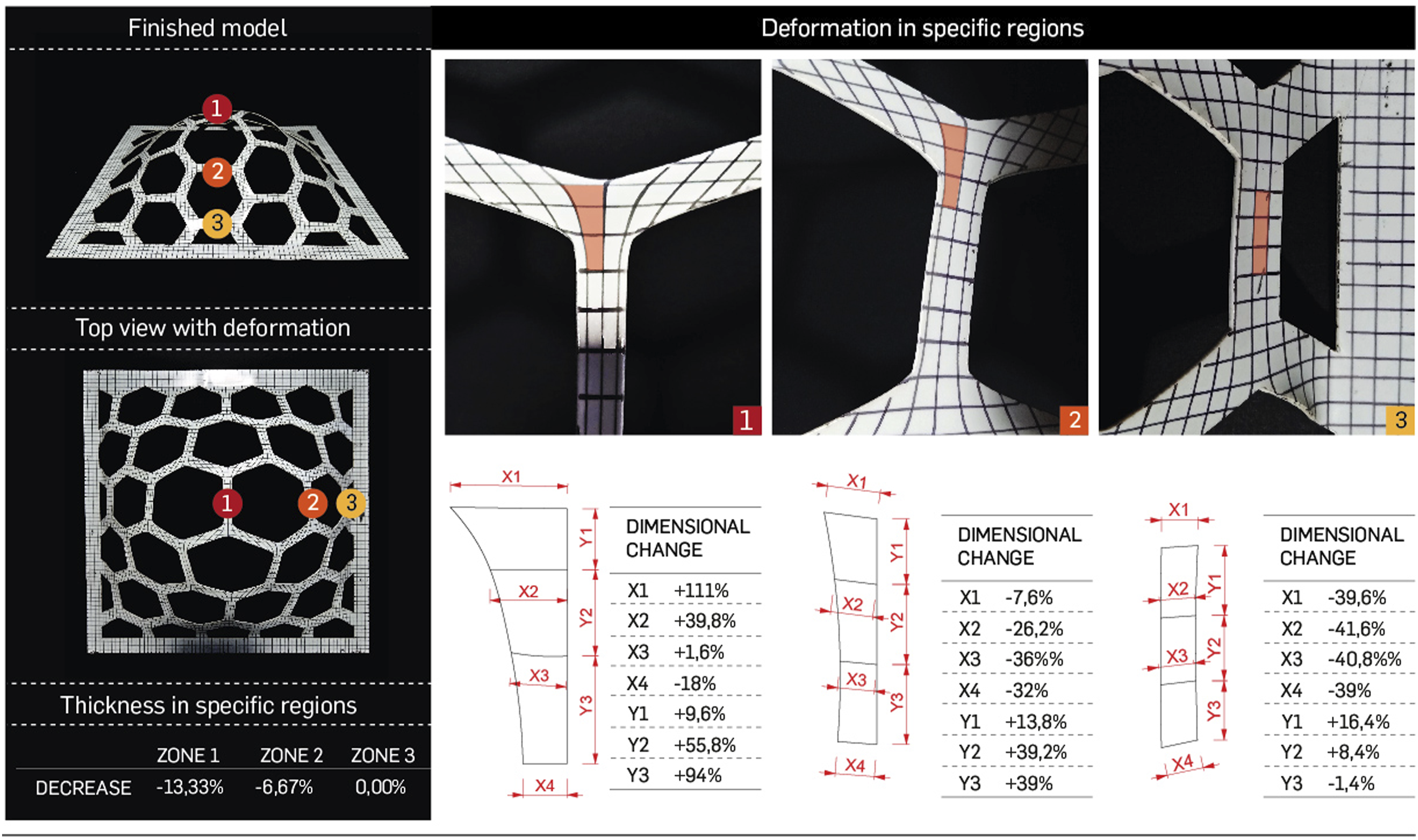
Computational algorithm
For designing the algorithms, the information verified in the analog procedure was used to computationally simulate the deformation test of Figures 8 and 9 and two additional results that used perforated sheets. Figures 13–16 graphically illustrate the logic of the algorithm developed in Grasshopper, where a surface (mesh) is divided into particles to simulate the behavior of the technique on them. The definitions were divided into three steps as follows. (i) Input: This is the step where the geometric properties of the surface, such as dimensions and location on the plastic sheet plane, are defined; (ii) Rule: In this step, information is provided to the particles of the plastic sheet to simulate the plastic behavior of the material under the influence of gravity and temperature; (iii) Output: This is the step in which the Kangaroo 2 solver is used to merge the properties of the particles and visualize the resulting shape. It is important to clarify that the heat source, material thickness, and type of polymer are constants that do not directly affect the algorithm. Algorithm logic of the basic test. Algorithm logic for the test without perforations with an irregular contour. Algorithm logic with hexagonal perforations. Algorithm logic with circular perforations. 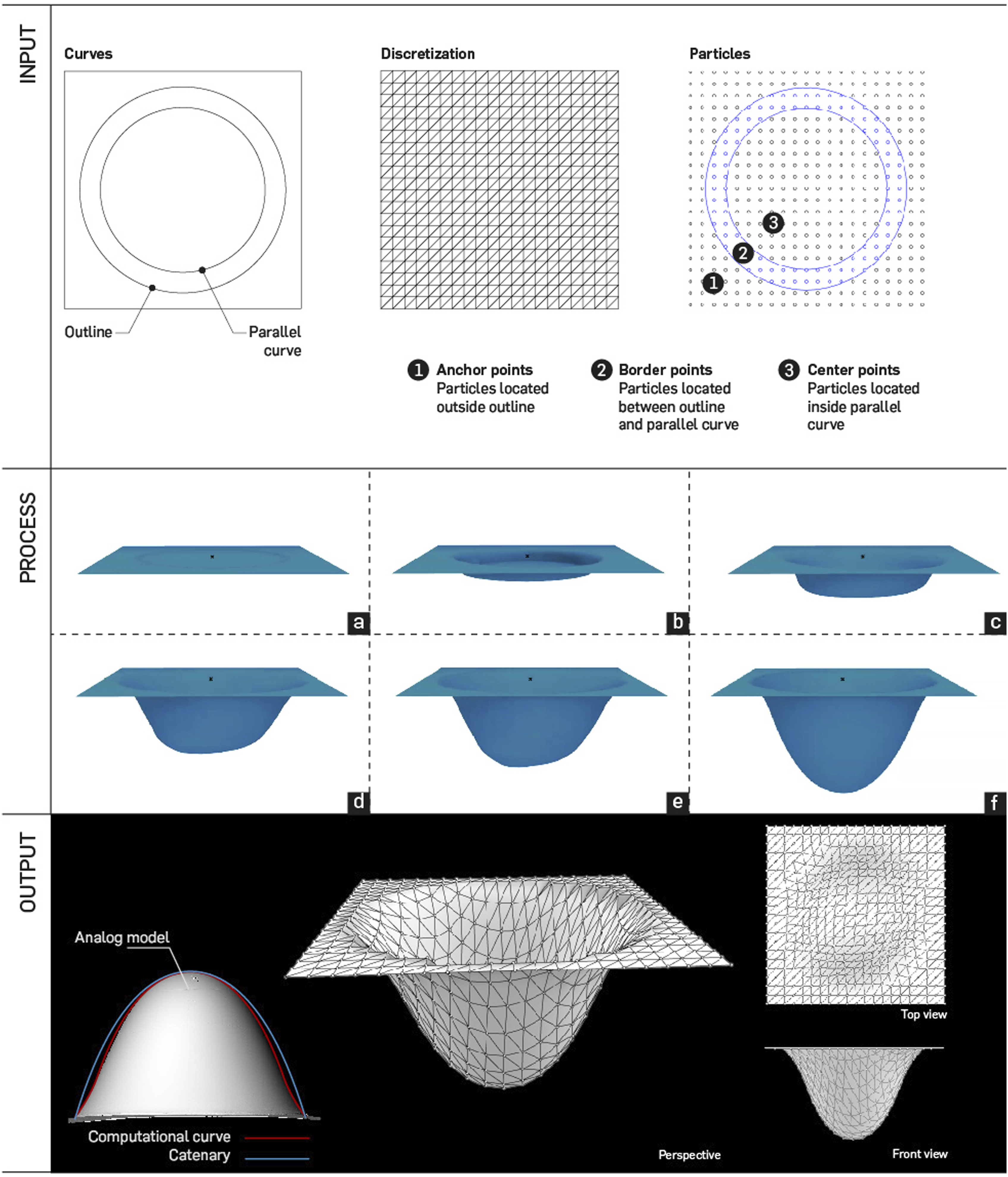
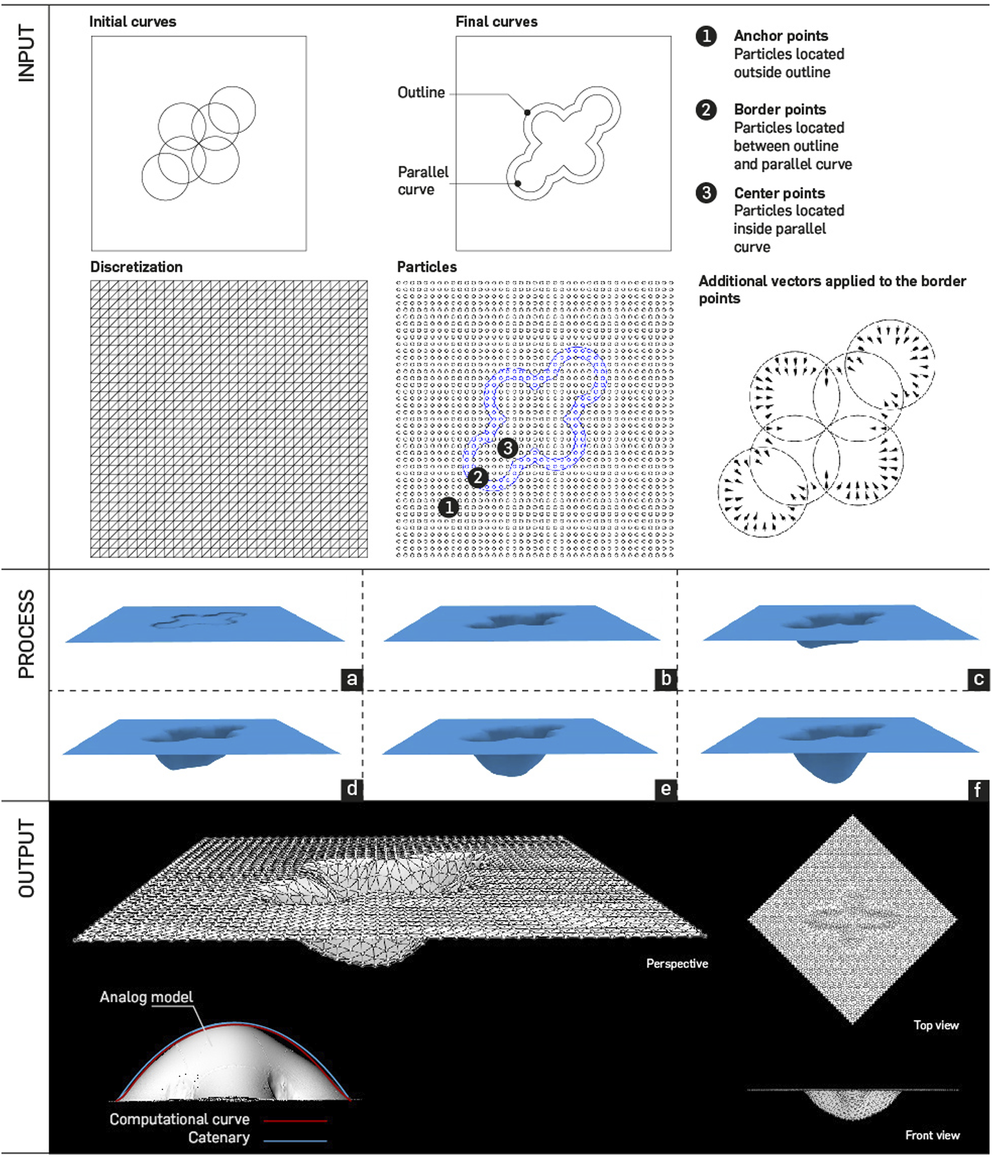
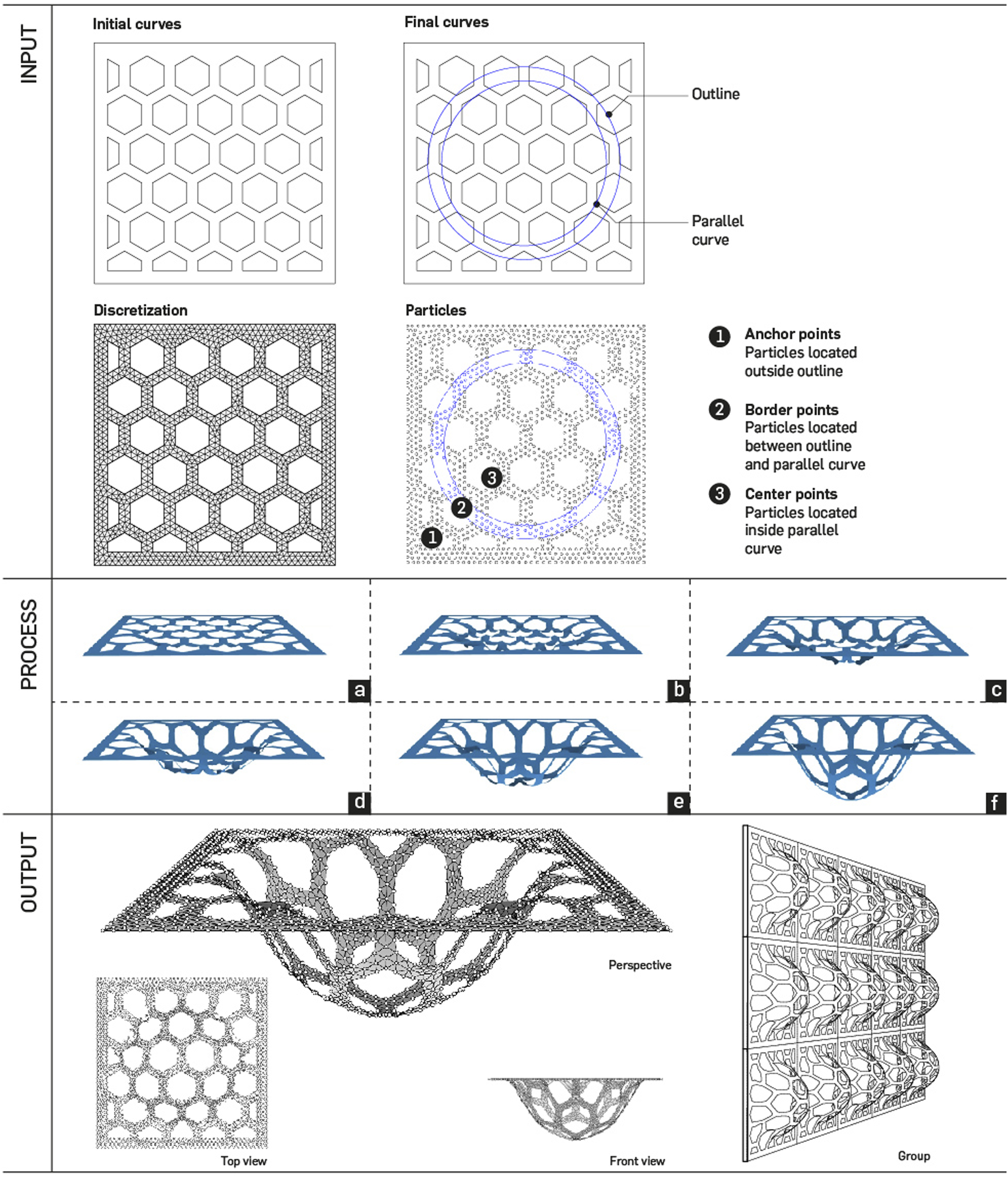
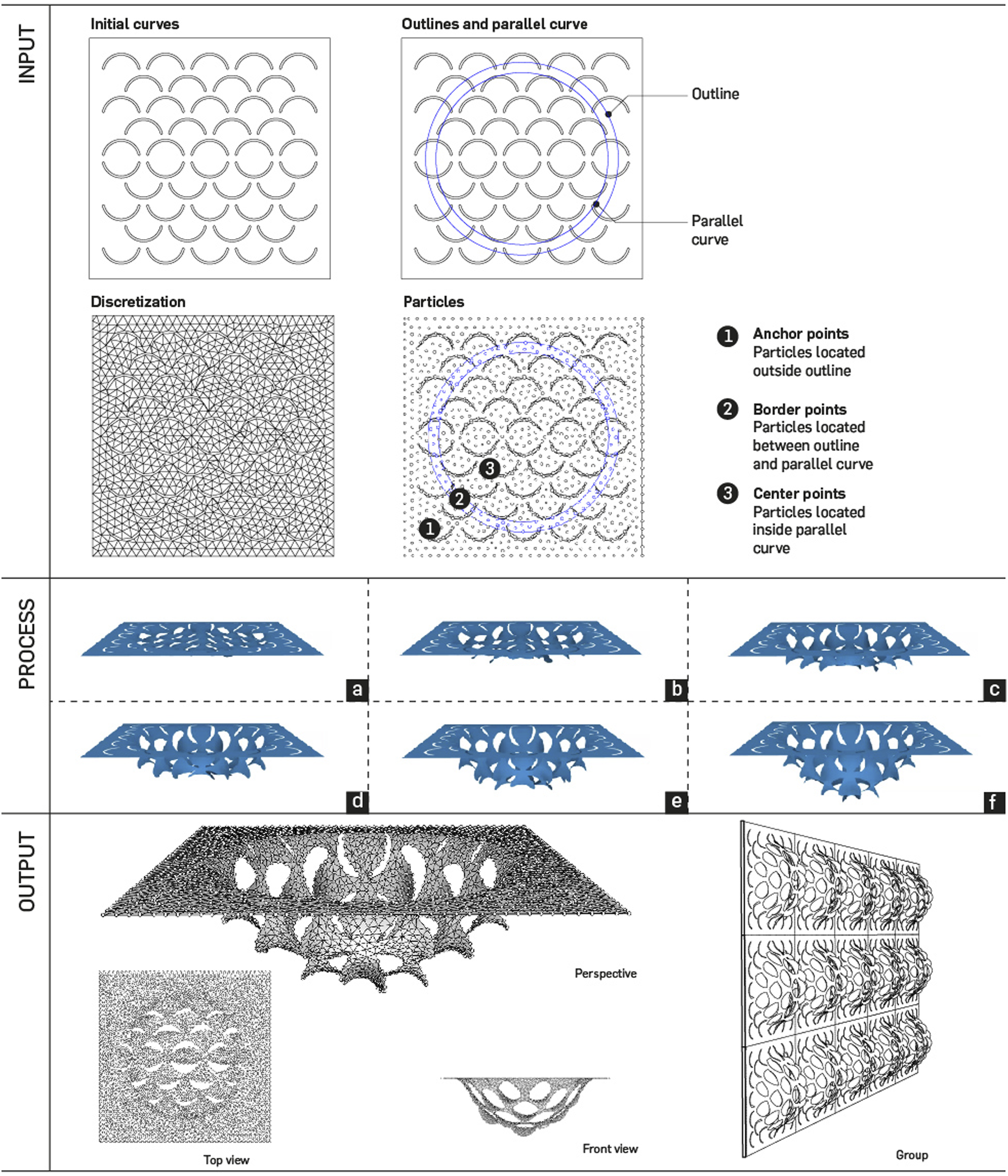
The results of the algorithms seem to indicate that the three moments of the algorithm can be replicated in other types of forms such as the models in Figure 4. In particular, the designer must define the anchor points, center points, and border points, which will have the function of supporting the physical attributes and thus generate the complex curved surfaces. Similarly, parallel curves are essential for locating the border points, which are the particles responsible for generating curves with double-negative curvature.
On the other hand, for the process described in the second moment, properties were attributed to the particles as follows: (i) the component gh. EdgeLenghs was used to give elasticity to the Mesh; (ii) anchor points were anchored; (iii) a load was applied to simulate the force of gravity to the center points; and (iv) loads were applied with vectors directed toward the center of the sheet to simulate the double-negative curvature as observed in Figure 10. Finally, the third moment includes the gh. Solver, which has the function of running all the information of the first two moments, and a mesh that is responsible for displaying the result of the simulation. At this stage, the resulting shape can be cut or grouped to generate a different type of structures (Figure 17). Algorithmic logic can be applied to experiment with all kinds of shapes. 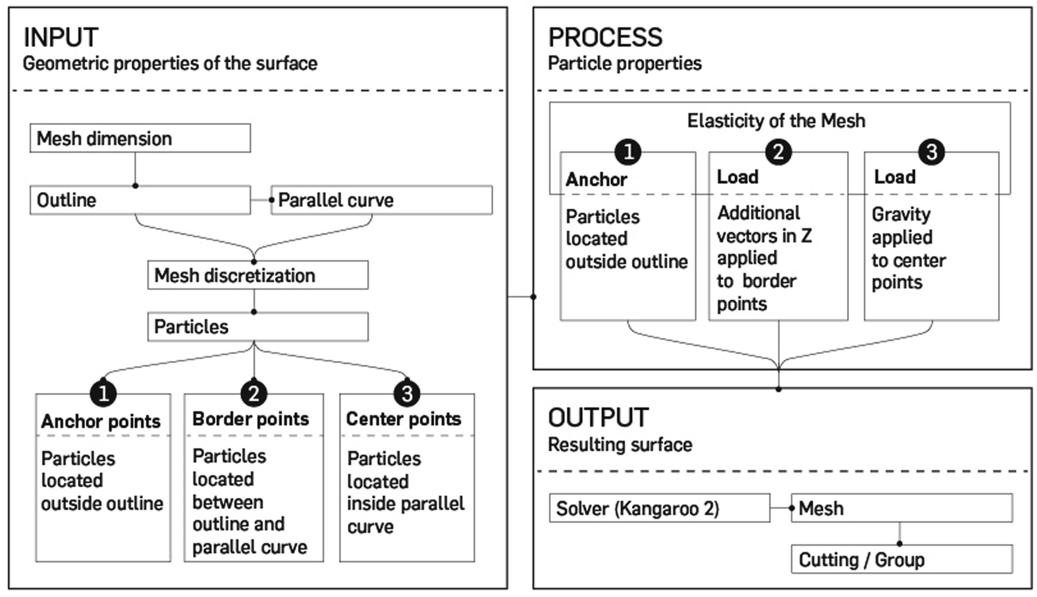
Potential applications
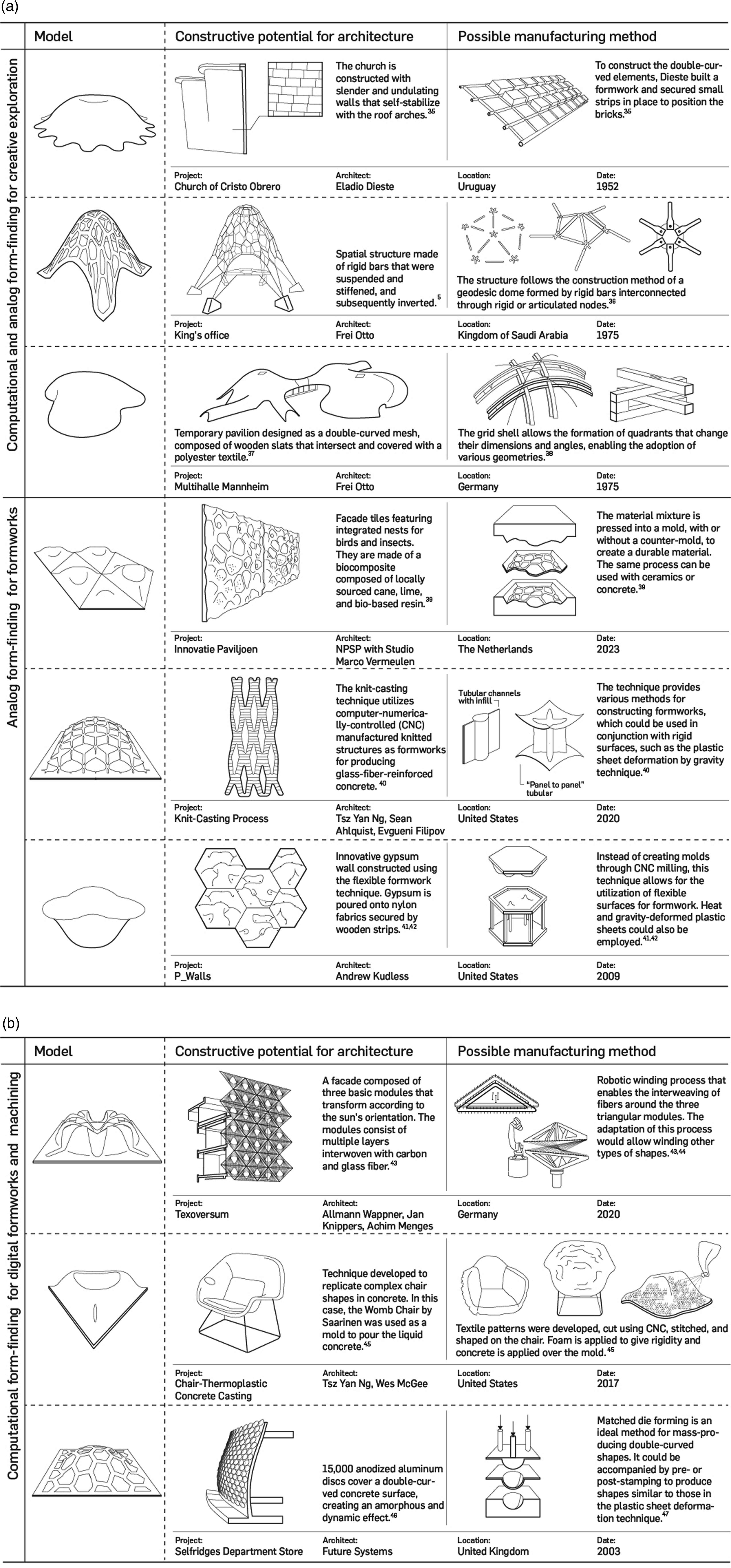
In Figure 18, the potential application of the technique is demonstrated by establishing relationships between some of the technique’s outcomes and design and architectural projects35–47. The projects were divided into three groups: (i) Computational and analog form-finding for creative exploration. This demonstrates the creative potential of the technique to inspire the generation of forms that can later be used in an architectural project. (ii) Analog form-finding for formworks. It highlights the technique’s capacity to generate formworks that can be used to cast biomaterials, gypsum, ceramics, or concrete. (iii) Computational form-finding for digital formworks and machining. It connects the technique with shapes that can be 3D-modeled using algorithms, subsequently manufactured through industrial manufacturing processes, using molds machined with CNC milling, or any other digital manufacturing procedure. Potential use of the technique. Authors’ drawings based on the indicated references.
Conclusions
The development of the form-finding technique based on the deformation of plastic sheets by the action of gravity and the increase of temperature serves as a basis for novel or expert architect practitioners, to analyze from an analog and computational approach, form-finding techniques based on the transformation of laminar material through stress.
The methodology implemented allowed us to explore different research tools that can be used in similar projects: (i) multifactorial design experiments for material selection from geometric analysis; (ii) semi-structured and qualitative experimentation to investigate geometric possibilities of a form-finding technique; (iii) morphological analysis of analog and computational models; (iv) analysis of the physical principles involved in the deformation of a material; and (v) translation of the inputs, rules, and outputs of an analog algorithm into a computational algorithm. Similarly, the developed algorithm enables the application of the same programming structure to other types of shapes, contours, and physical constraints.
On the other hand, the geometrical properties of the models, their variety and complexity, allow the developed technique to be a powerful creative tool to generate stimuli that propitiate the search for novel forms in an agile way. The analog approach of the technique has the virtue of being free of high cognitive efforts since the designer can let the physical principles act autonomously; moreover, it provides the tools to understand the physical processes before starting the programming. On the contrary, the computational approach of the technique presents a high investment of time, especially in the preliminary stage, which is compensated when the algorithm is developed since the designer can generate the shape quickly without incurring into material costs and without using specialized machinery.
To conclude, the technique’s versatility makes it suitable for a wide range of creative and practical purposes across multiple industries and contexts. The potential use of the technique could include the following: (i) Architectural Applications: Creating innovative building facades, roofing, and structural elements with complex, double-curved geometries. (ii) Art and Sculpture: Producing artistic sculptures and installations that feature intricate shapes and patterns. (iii) Industrial Design: Developing unique and aesthetically appealing product designs for various industries. (iv) Aerospace and Automotive: Designing lightweight and aerodynamic components for aircraft and vehicles. (v) Environmental Design: Incorporating sustainable and visually appealing elements into landscape and environmental designs. (vi) Furniture Design: Crafting custom furniture pieces with innovative and ergonomic designs. (vii) Research and Development: Exploring new possibilities in material science and manufacturing processes. (viii) Education: Teaching and learning about advanced architectural and design concepts. (ix) Prototyping: Rapidly prototyping complex forms and structures. (x) Custom Manufacturing: Producing one-of-a-kind, custom-built structures or components for specialized applications.
Footnotes
Acknowledgments
The authors would like to thank Alejandro Zuleta-Gil from Universidad Pontificia Bolivariana (Medellín, Colombia), Andrés Montoya, and Jairo Madrigal from Instituto Tecnológico Metropolitano (Medellín, Colombia), for their guidance on materials science and physics fundamentals.
Declaration of conflicting interests
The author(s) declared no potential conflicts of interest concerning the research, authorship, and/or publication of this article.
Funding
The author(s) received no financial support for the research, authorship, and/or publication of this article.