
Abstract
This paper presents an innovative design and fabrication workflow for a lightweight composite slab prototype that combines mineral foam 3D printing (F3DP) and concrete casting. Non-standardized concrete elements that are geometrically optimized for resource efficiency often result in complex shapes that are difficult to manufacture. This paper extends the research in earlier studies, showing that F3DP can address this challenge. F3DP is used to construct 24 stay-in-place formwork elements for a lightweight, resource-efficient ribbed concrete element with a 2 × 1.3 m footprint. This advancement highlights the improved robotic F3DP setup, computational design techniques for geometry and print path generation, and strategies to achieve near-net-shape fabrication. The resulting prototype shows how complex geometries that were previously cost-prohibitive can be produced efficiently. Discussing the findings, challenges, and future improvements offers useful perspectives and supports the development of this resourceful and sustainable construction technique.
Keywords
Introduction
According to the UN Environment Program’s Global Status Report for Buildings and Construction, production emissions of building materials, including cement, steel, and glass, are rising and account for 10% of all carbon emissions worldwide. 1 Cement production alone is responsible for about 7% of the total. Therefore, it is essential to lower the cement content of concrete buildings to meet the sustainable development objective of responsible consumption and production (SDG12).
In favor of ease of fabrication and cost-effectiveness, most concrete used in construction nowadays is used for standardized flat cast floor slabs that are large, monolithic parts. 2 This focus on costs is misguided, though, as slabs not only consume the most volume of materials in concrete-framed buildings and have the greatest embodied carbon levels, but they also make up the majority of a structure’s mass. As a result, this necessitates an overall stronger load-bearing structure for buildings and raises the amount of energy and costs needed for construction logistics.
Numerous methods exist for optimizing slabs to be material-efficient and lightweight. Hollow-core slabs, for example, are pre-fabricated elements made by extrusion with continuous tubular voids and used to cover standardized spans. An on-site approach involves placing hollow forms in portions of the slab where structural strength is not required; the remaining area is then filled with a concrete cast.3,4 This is more difficult for the geometrically complex formwork of non-standard slabs. Their manufacturing often involves wasteful subtractive techniques, they are not reusable for other slab geometries, and they demand more materials and labor, all of which raise the cost of the product.
These material efficiency and sustainability strategies have changed with additive manufacturing (AM) in the construction industry because differentiated shapes may now be produced without molds, production-specific tooling, or additional labor. As a result, several studies used AM methods for creating the formwork for novel, material-efficient, lightweight concrete slabs.5,6
This study presents an innovative fabrication workflow employing mineral foam 3D printing (F3DP) and concrete casting. In the context of the design and construction of a lightweight composite concrete slab prototype, challenges are highlighted, and strategies for improvement are discussed. This work represents the next phase in the body of research looking at F3DP for applications on an architectural scale. This idea has already been researched in a pilot study using sintered mineral foams for a composite facade shading panel 7 and an arched beam floor system. 8 In the current study, the material and robotic fabrication system are improved. The fabrication of 24 freeform stay-in-place formwork components is demonstrated at higher precision due to the implementation of machine vision and 3D scanning. These formwork components are used with fiber-reinforced ultra-high performance concrete (UHPFRC) to produce a prototypical 2 × 1.3 m ribbed concrete slab geometry.
The material and F3DP system are presented alongside computational design workflows, advanced print path generation, and infill pattern assessment. 3D scanning procedures are used to improve the print path and mitigate target shape deviations. Compared to monolithic slabs, the resulting prototype uses 72% less concrete, resulting in a 70% lower mass. The filigree ribbed geometry is a generic example for optimized concrete structures 9 and is designed as a use case for formwork fabricated by F3DP. Discussions of the benefits and challenges of this innovative production technique are complemented with suggestions for future advancements.
Opportunities of foam 3D printing
Mineral foams are materials that contain a considerable volume of entrapped air. They are lightweight, fire-resistant, and offer good insulation and acoustic qualities. 10 Therefore, they are frequently employed in the construction industry as insulators to strengthen the thermal resistance of buildings or as non-load-bearing wall and floor layers to reduce the dead weight of structures.
Pre-fabricated boards and blocks, sandwich panels, custom freeform elements, and on-site casting or spraying solutions are the most typical ways foam materials are employed. Due to their excellent machinability and high strength-to-weight ratio, foams are particularly well-suited for formwork applications. Traditional ways of processing foam to achieve intricate shapes for custom formwork are cutting and milling of larger blocks. These subtractive techniques cause significant amounts of waste from chipping and offcuts. Additionally, this makes utilizing the material efficiently in geometrically complex building components exceedingly challenging.
However, additive manufacturing (AM) in construction is a promising approach for more sustainable and efficient fabrication processes,11,12 with numerous chances to improve building with foams using foam 3D printing (F3DP). 13 F3DP enables automating the waste-free production of intricately shaped building components using porous building materials. This makes fabricating stay-in-place forms for specially designed, geometrically efficient building parts easier. Furthermore, the high heat and sound insulation capabilities of foams can also enhance the functionality of wall and slab components. As a result, F3DP makes it possible to create novel composite structures that utilize less material and are more lightweight and portable while boosting worker productivity and safety at the same time.
State-of-the-art and challenges
F3DP for stay-in-place formwork has been the subject of several studies in the past. A prototype dome and a one-story residential home’s stay-in-place formwork were constructed using expanding polyurethane spray foam.14,15 For F3DP, though, more environmentally friendly, cement-free, and naturally non-flammable mineral foams exist and were applied in this study. In the past, F3DP with mineral foams has been used in a number of small-scale investigations,16,17 the prototyping of climate-responsive bricks, 18 and the creation of a lightweight composite facade shading panel. 7 However, these studies used sintering, a highly energy-intensive technique, for material consolidation. Additionally, cement foam mix designs and production methods were examined for large-scale F3DP19,20 and the fabrication of parts with varying densities. 21 The dimensional accuracy of the elements created by F3DP is not discussed in any of these investigations, though.
With F3DP, geometrical errors happen when the extruded material is placed and quickly changes from fluid to solid. This transition may cause a volume change, leading to an unknown print geometry. Furthermore, long-term curing is needed following manufacturing in the case of alkali-activated mineral foams, which may cause the solid specimen to shrink. These phenomena provide difficulties for near-net shape fabrication techniques that ideally do not require further post-processing.
Designing at layer-scale
The design of the print path has a significant impact on the printing process, the behavior of the material during deposition, and the physical properties of the finished part. Printing times for a given geometry can greatly vary depending on the chosen path strategy and affect the economy of this production method. The print path design determines the motion profile of the robotic deposition system and can lead to increased wear and even damage. Moreover, the print path affects the surface properties of the final part, such as roughness or porosity. Finally, the physical properties of the printed part, such as strength and mass, are also influenced by the spatial arrangement of the printed material.
Different print path schemes can be chosen for specific performance objectives. Existing research lists numerous categories with suitable path planning and AM technologies, such as surface quality, shape, and corner accuracy, infill distribution, saving time, material, and weight, improving mechanical properties, achieving thin-walled geometries, functional grading, isotropic parts, and easy print bed removal. 22 Another study, for example, used advanced print path design and varying robot speed to create parts with functionally graded density, specifically lightweight beam elements fabricated by concrete 3DP. 23
In general, print path strategies can be distinguished between planar and non-planar. For the former, Ding et al. argue that infill path patterns can be categorized into six main types. 24 Raster paths are based on planar ray casting, creating disconnected direction-parallel lines within a given 2D contour. The zigzag path approach is derived from the raster method and connects the resulting lines in an undulating manner into one continuous path. Contour paths are another strategy based on iso-contours of the Euclidean distance transform and result in disconnected curves, which follow the geometrical features of a given 2D contour. A derivation from this is the spiral path, which connects the disjoint iso-contours into one continuous path. More sophisticated are connected Fermat spirals because they start and end in the same location. 25 Space-filling paths are another approach that generates continuous curves, which cover a given 2D contour without intersecting itself. Maze-like path schemes belong to this category and are known to produce complex, labyrinthic, continuous line patterns. 26 Hybrid path strategies are derived from the types mentioned above and combine both approaches of direction-parallel and contour-parallel path algorithms. Bi et al., for instance, propose a continuous contour-zigzag print path that enables solid and partial infill patterns to be printed more efficiently with fewer sharp turns. 27
Methodology
The following section covers the main methods used in this experimental study. First, the material and 3D printing system are introduced. Then the design strategy for the formwork elements of the slab prototype is elaborated in detail, followed by investigations of print paths and, more specifically, infill patterns. Last, methods to overcome the challenges of dimensional accuracy of F3DP are proposed. Long-term specimen assessment can be used to forecast deviations and modify the print strategy. This work suggests using 3D scanning to analyze long-term shrinkage and correct target geometry deviations during toolpath processing. Using a geometrical pre-scaling factor for toolpath generation based on 3D scanning findings, the initial results demonstrate a considerable improvement in printing accuracy.
Material and 3D Printing System
Fly ash, a by-product of industrial coal combustion, is the primary ingredient in the sustainable mineral foam employed in this project. Fly ash hardens and sets like cement in an alkaline environment, gaining its full strength after mild heat curing.28–30 Compared to earlier research that utilized sintering for material consolidation, this represents a substantial advancement.
In the first step, the material is prepared for printing. This entails mixing fly ash, water, and additives in a planetary mixer. After that, a continuous flow of slurry and hardener is pushed into a foam generator, which combines and foams the two ingredients in a specified ratio.
The slowly hardening foam that results from this process moves inside a flexible hose from the foam generator to the ABB IRB 1600 robotic arm, which performs the printing motion (Figure 1). The robotic trajectory and printing speed are computed by the digital path generator tool, which is discussed in more detail in the following section. Rigid wooden plates are used as print beds with a footprint of 55 × 95 cm. Robotic F3DP setup: foam generator, slurry, and hardener pumps connected to the IRB1600 with a flexible hose.
31
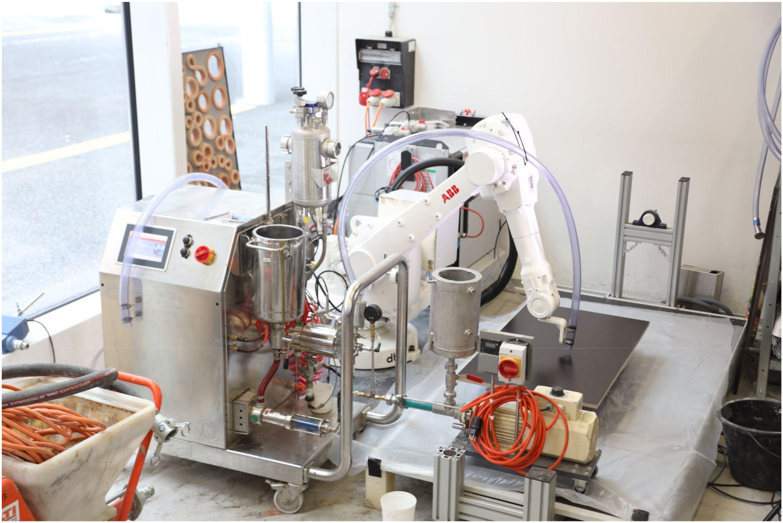
The system enables the production of 100 L of foam from up to 40 L of slurry with wet densities of about 500 kg/m3 during each experiment. Robotic printing at a speed of 110 mm/s deposits the foam at a 2.1 L/min extrusion rate. After printing, the printed parts are kept at 40°C for the first day in a humid environment (about 70% RH) and for a further 6 days in a dry environment (around 45% RH).
Element Design
The slab prototype serves as a case study for the innovative manufacturing approach that combines traditional concrete casting with F3DP of formwork. The resource-effective form is shaped by the elements of custom-printed sustainable mineral foam. UHPFRC, which is a high-performance load-bearing material used in the building industry, was chosen, along with typical rib dimensions. It is anticipated that the slab prototype’s structural performance will be comparable to slabs built with traditional formwork composed of polystyrene or wood. 9 Consequently, this study did not include any structural evaluation. Instead, an evaluation of the F3DP procedure, the subsequent fabrication steps, element and print path design, and strategies for deviation mitigation were investigated.
Techniques based on the ribbed floor slab systems of the pioneering structural designer Pier Luigi Nervi 32 are used to construct the generic geometry of the slab prototype. 28 In order to specify the position of structural floor ribs, isostatic lines that are derived from the major stress pattern occurring in a certain boundary and loading situation are used. Various research studies exist on optimizing the geometry of slab elements using vaults and shell structures.9,33,34 In contrast, this study uses an exemplary geometry for formwork made by F3DP with ribs in tension.
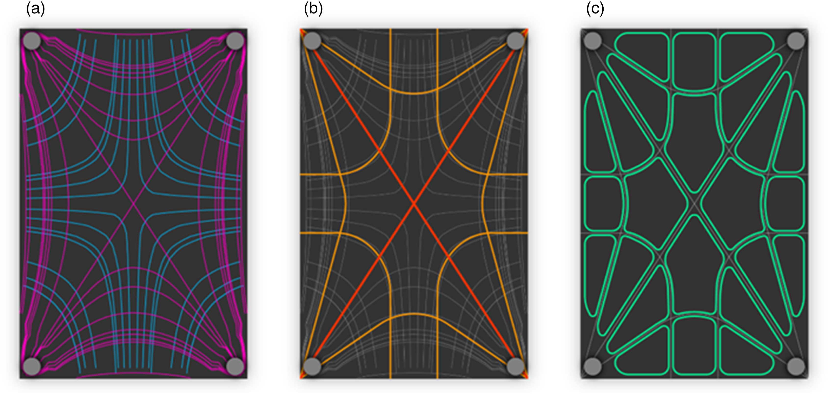
As a first step, a finite element analysis (FEA) is conducted to analyze the major stress pattern. The analyzed geometry is a rectangular concrete slab measuring 2 × 1.3 m, with 14 cm thickness. The support is defined with four points, one in each corner of the rectangle. The anticipated dead load for residential use is an evenly distributed area load of 2 kN/m2. The resulting stress pattern is translated into a simplified hierarchical rib layout in a second step. The negative space between the ribs defines the custom stay-in-place formwork geometry (Figure 2). Slab layout design stages: a) principal stress pattern derived from FE analysis, b) simplified hierarchical rib lines, and c) final formwork elements.
31
The rib thicknesses are not structurally optimized but pronounced in 25 and 40 mm thicknesses, as example geometry. The number of ribs was chosen to divide the slab into formwork pieces of the same size, fitting into the robotic F3DP fabrication area.
The formwork for the ribs comprises 24 foam parts with 12 pairs of similar geometry because of the symmetric load situation and stress pattern. The overall thickness of the slab prototype is 14 cm. This results from the 10 cm high foam elements and a 4 cm concrete coverage. The outline curvature of the foam elements is tailored for the F3DP process’s resolution, and their corners are rounded off to minimize the possibility of over-extrusion. The hierarchical ribs have two different thicknesses of 25 and 40 mm.
Path Design
Print path design and part geometry are highly interdependent. Hence, when designing the path layout, the type of target geometries and specific performance requirements have to be considered. In this study, the formwork elements are simple extruded polygons that must be produced with all boundary surfaces closed, which means solid infill patterns. The option of printing their boundary surfaces as shells and then casting the infill in a second step was discarded to avoid an additional fabrication step and potentially slower production speed.
The formwork elements should be lightweight for handling and strong enough to resist the hydrostatic pressure of the concrete during the final casting step. Their simple geometries do not require curved-layered printing paths and can be designed as successive planar print layers. Since the developed F3DP setup does not offer start–stop operations, the print path should be continuous, or travel moves should be minimized as much as possible.
Previous studies have shown that direction changes in the print path design for solid infill patterns influence the bulk density of the filled volumes. 35 More changes introduce under-extrusion areas in tight turns and reduce the final density. Moreover, infill patterns with excessive turns, like space-filling curves, also increase the layer length, hence, the overall printing time. For this reason, they are not considered an option for the print path investigation in this study.
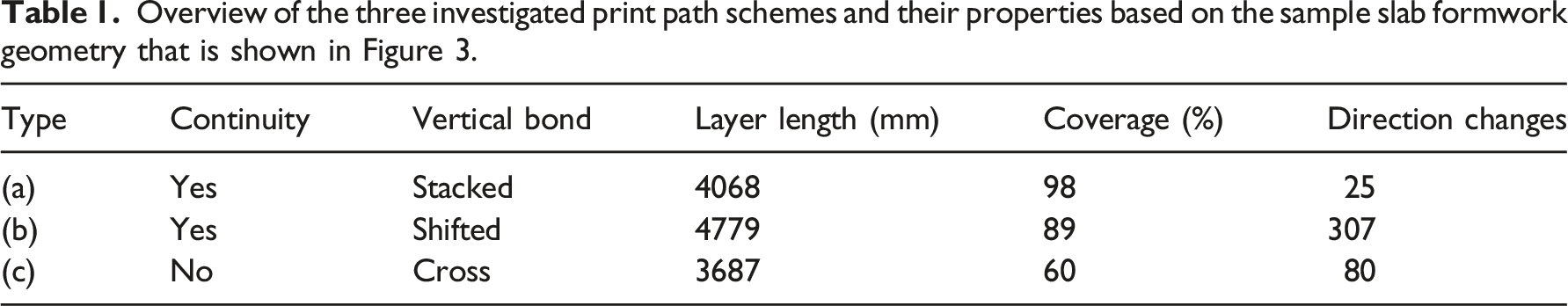
The infill path designs that were considered in this study are shown in Figure 3, where they are applied on test geometry from the slab prototype formwork. They consist of (a) a direction-continuous spiral, (b) a contour-perpendicular zigzag pattern, and (c) a direction-parallel cross zigzag pattern. Table 1 shows, in an overview, how the design options perform differently in print metrics evaluated from slicing the test element. The following section describes the individual print path designs in detail. Three investigated print path design options: (a) direction-continuous spiral, (b) contour-perpendicular zigzag, and (c) alternating direction-parallel zigzag. Overview of the three investigated print path schemes and their properties based on the sample slab formwork geometry that is shown in Figure 3.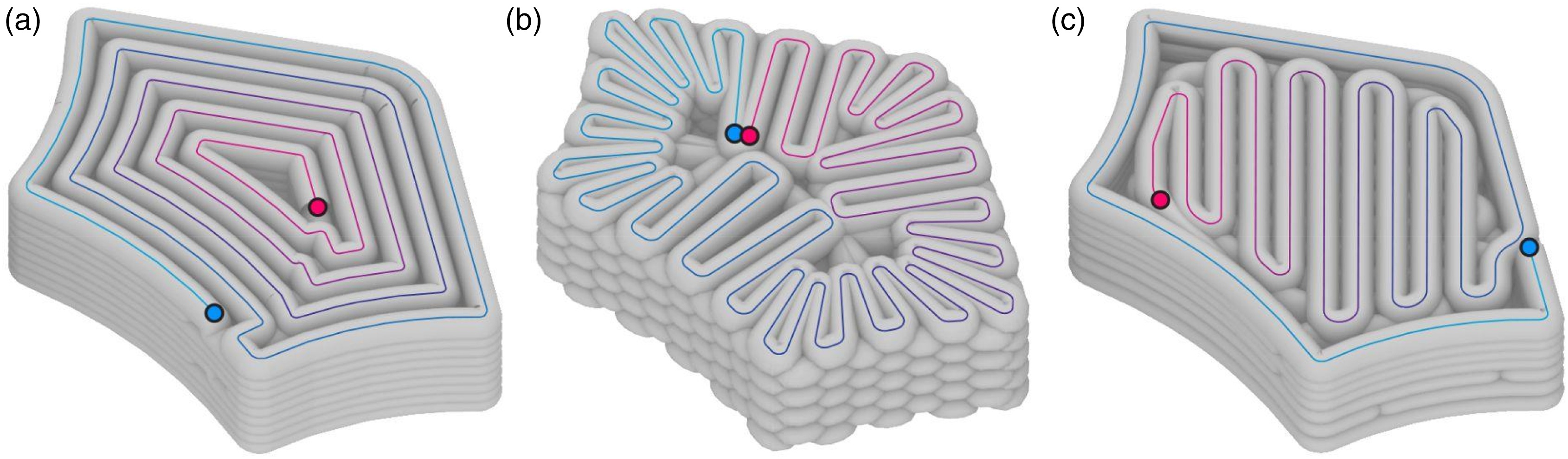
Firstly, a direction-continuous spiral belonging to the contour-parallel infill pattern category was examined. It creates a continuous print path without reversing the direction at the layer change. This is achieved by spiraling successive iso-contours on each layer individually, starting from the closest point to the endpoint of the previous layer. As a result, every spiral in each layer is unique and connects iso-contours from outside to inside or in reverse. The vertical bonding pattern aligns the print paths in a stacked manner because, in this study, they are based on the contours of vertically extruded geometries.
The direction-continuous spiral pattern produces a print path that is 4068 mm long for the tested geometry of the formwork element with a high infill coverage of 98%, resulting in few gaps from under-extrusion in sharp turns. The resulting print path has only 25 critical direction changes. For quantifying them, all paths were sampled into 500 segments. They were counted as critical if the angle between the segment start and end tangents exceeded 100°. The angular threshold was established empirically to reduce the change in robot speed in tight turns of the print path. This infill pattern is independent of the shape of the print object. Only at the center of the infill pattern under-extrusion and gaps can appear.
Secondly, a contour-perpendicular zigzag pattern was developed, a hybrid strategy of contour-parallel and space-filling curves. It creates continuous and closed print paths in each layer by zigzag traversing the filling area radially along an outer and inner iso-contour offset. The zigzag lines are shifted in each layer to create a shifted vertical layer bond. This pattern produces a print path of 4779 mm for the tested geometry with an infill coverage of 89%. Thereby, it is shape-dependent and better suitable for elongated print geometries such as wall elements, where the length of the contour and the inner offset path are similar. Areas of under-extrusion can occur at the center of the infill pattern, which would be much more pronounced with compact shapes. With the high amount of critical direction changes of 307 sample segments, this pattern takes particularly long to fabricate.
Lastly, a direction-parallel zigzag infill pattern with alternating layer orientation was tested. The scheme creates continuous open print paths with different directions, start, and endpoint locations in each layer, which results in travel paths in every layer transition. Consequently, the vertical layer bonding is alternating crosswise. The infill pattern produces a 3687 mm long print path with a low infill coverage of 60%. This results from the under-filling area between the direction-parallel zigzag pattern and the outer contour of the print geometry. Hence, this scheme is highly shape-dependent, and the direction of the zigzag pattern ideally follows key geometric contour features. Applied to the test geometry, this infill pattern features a moderate amount of 80 critical direction changes.
Finally, the first print path scheme was chosen to fabricate the formwork elements for the slab prototype. It performed best in infill coverage and critical direction changes when tested with the sample geometry, promising an efficient printing process with high accuracy and less post-processing of the finished part than the other schemes. Moreover, travel moves could be avoided, and the resulting surface quality of smooth continuous layers satisfied the application case as formwork.
The print pathways of the described F3DP process are calculated using python scripts in the Rhino/Grasshopper environment and the COMPAS framework.
36
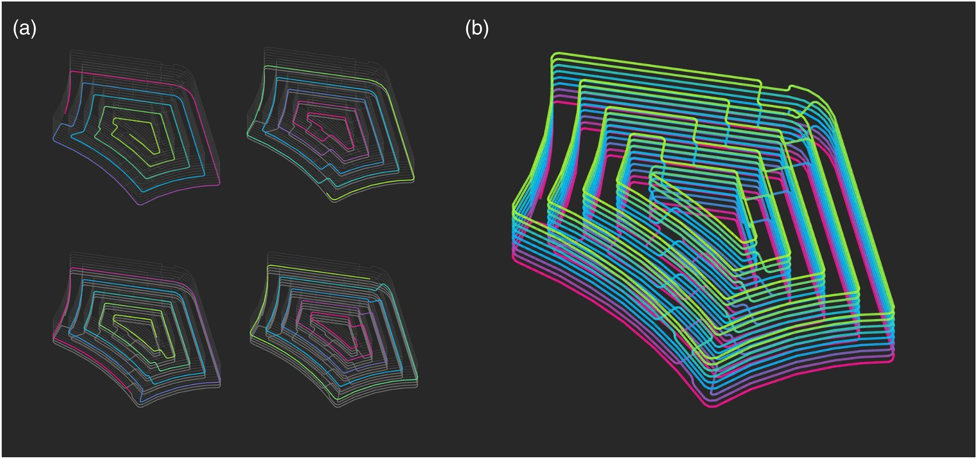
The generated print path design and resulting fabrication metrics can then be displayed in the CAD environment, allowing formwork shapes to be selected, processed, and rendered (Figure 4). The input variables layer height, layer width, and material flow rate are used by the print path generator to calculate printing speed. The print geometries are pre-scaled vertically by 1.2, which was determined empirically by 3D scanning test specimens with the intention of enhancing dimensional accuracy.
37
Print path visualization showing (a) sequence of different layers and (b) all layers of sliced print geometry.
31
Robot targets and speed data are included in the fabrication data, which are exported as JSON files. Using the COMPAS framework and the COMPAS RRC package, 38 robot operations are carried out. The F3DP processing equipment is operated manually during fabrication, and the flow rate of the material is kept constant. The robot operator can scale the planned speed values in the event that deviations occur.
3D Scanning
In order to achieve a process quality for the fabrication of near-net-shape parts, the geometric deviations of the printed geometry from the digital model must be evaluated. These variations can happen both during printing due to the plasticity of the wet material and after printing due to the shrinkage of the curing material. The variations are measured by implementing a multi-step, post-printing 3D scanning process and comparing the generated 3D data with the original geometry.
The prints were scanned using a portable structured light 3D scanner of the Creaform GoScan 50 type directly following printing and in their final cured state. A total of 12 printing cycles were recorded, with 1–3 specimens being scanned for each cycle in both fresh and cured states. The obtained data were processed in the proprietary scanner program VX Elements, and an exported 3D mesh with an average of 450.000 vertices and the accompanying target marker coordinates were produced. It was not possible to collect raw point cloud data from the proprietary scanner software.
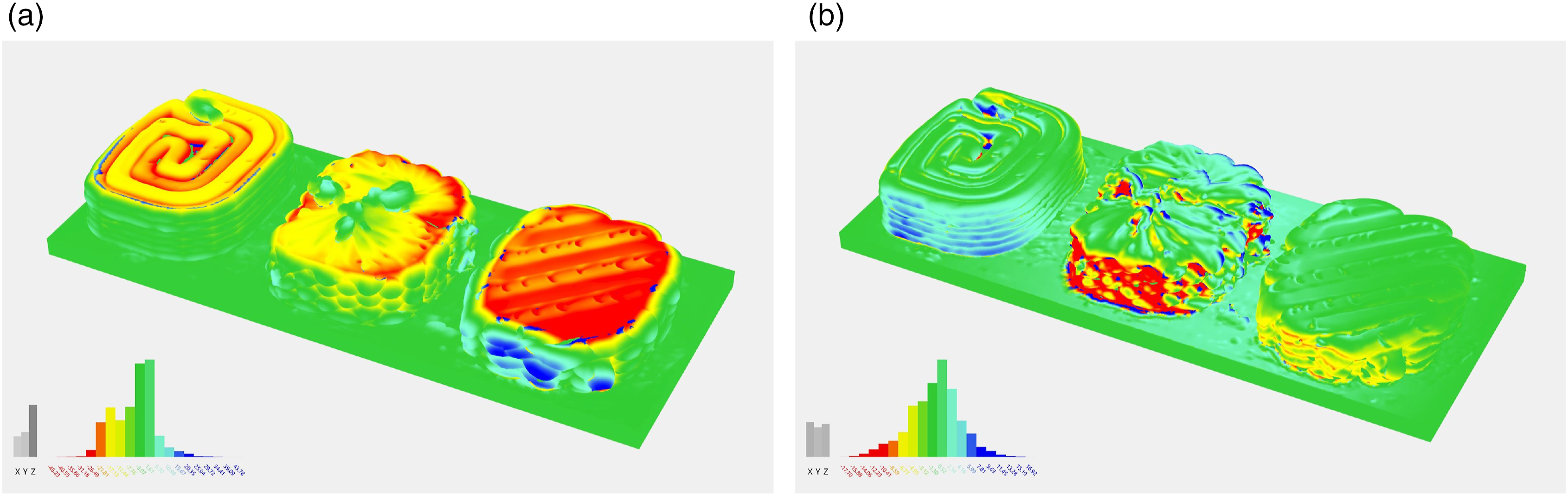
A customized script in the Grasshopper plugin was then used to examine the meshes in the Rhinoceros CAD program. First, the meshes were initially aligned and layered using the coordinates of the target markers. Second, a calculation was made to determine the distance between each vertex of the mesh under analysis and the nearest point on the comparison mesh. Distance data were mapped into the positive or negative domain depending on whether the comparison mesh is inside or outside the boundary. Third, a histogram that displays the absolute and axial (x; y; z) distribution of the mapped deviation distances was constructed for the analyzed mesh, which was color-coded to visualize the magnitude of the deviations (Figure 5). (a) Deviations between fresh print and digital target geometry and (b) between cured and fresh print.
37
Fabrication of the Demonstrator
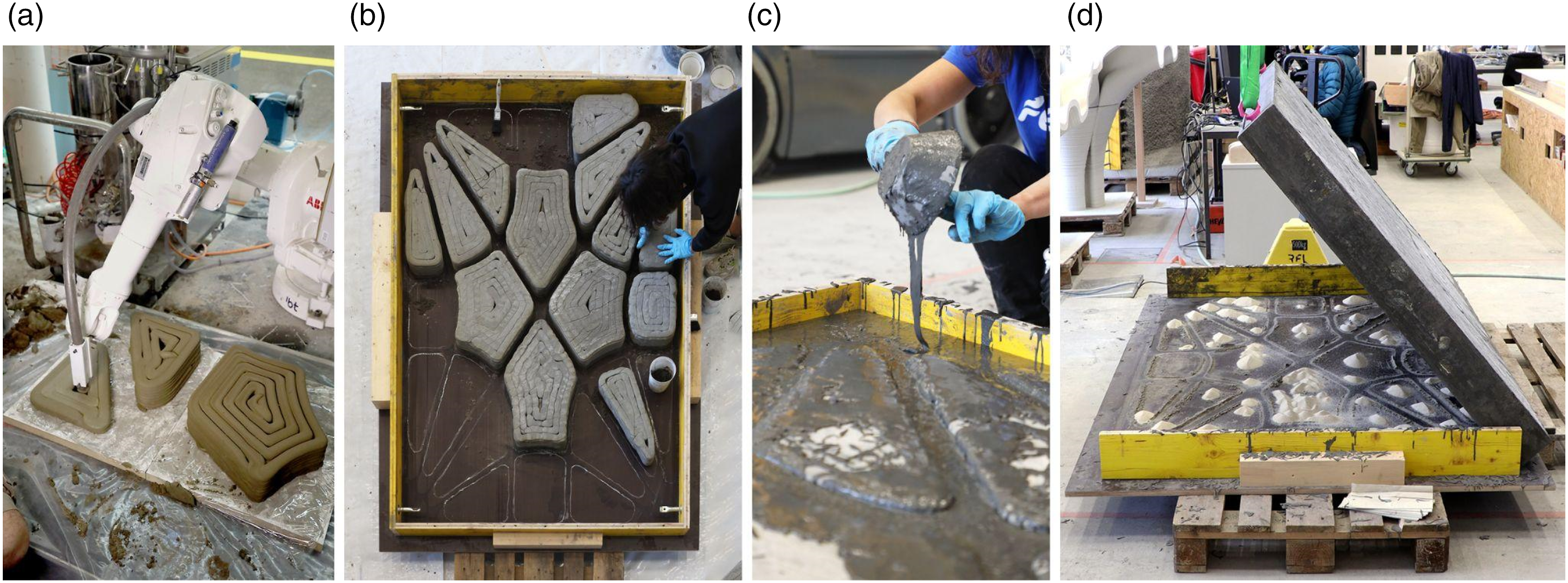
Four main steps were necessary to fabricate the prototype of a ribbed concrete slab: printing the foam elements, utilizing the printed elements to build a formwork, casting concrete, and removing the formwork (Figure 6). Fabrication steps: (a) printing foam elements, (b) preparing temporary timber formwork and stay-in-place foam elements, (c) casting UHPFRC, and (d) removal of temporary formwork.
31
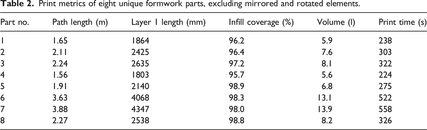
Print metrics of eight unique formwork parts, excluding mirrored and rotated elements.
Second, a rectangular wooden formwork with the interior measurements of the prototype concrete slab, 2 × 1.3 × 0.14 m, was constructed. Then, a chalk outline was placed on the lower surface of the formwork to represent how the foam elements would be laid out. Next, one by one, the cured foam components were put into place. With the intention of preventing the lightweight foam elements from floating during casting, their bottom perimeter was sealed manually using a mixture of sand, water, and fly ash. The foam components were then covered with dry sand, which is used to plug any gaps where concrete might eventually seep in. All 24 foam components needed to be manually prepared, which took 15 min for each foam element, or 6 h total.
Third, a UHPFRC mix with the formulation and mixing method described in Reference [5] was employed for casting. A team of six persons slowly poured the concrete into the formwork after mixing it in 30 L portions. Before the pieces were covered with a continuous coating of concrete, the space between the foam elements was filled at a slow and spatially distributed constant vertical casting rate. The prototype was placed in the unheated fabrication hall and permitted to cure for 3 weeks while being covered in a plastic foil to prevent the evaporation of water from the surface of the UHPFRC.
The slab prototype was then turned upside down to reveal the ribbed geometry created by the printed formwork after the wooden formwork had been removed. The final appearance was achieved by flushing out the loose sand and dry sealant around the foam components using compressed air. Because the mineral foam can be recycled, half of the formwork elements were removed from the prototype to reveal the space they filled out. In principle, the removed foam can be used to print new formwork elements.
Results and discussion
Despite the fact that no structural assessment of the slab prototype was performed, this study could show that using F3DP for bespoke stay-in-place formwork is highly relevant for custom-designed, non-standard concrete structures. The proposed approach makes constructing material-efficient ribbed slab shapes possible, thanks to a manufacturing technique that drastically lowers material waste compared to conventional methods for bespoke formwork.
A sizable number of foam parts for a real-scale prototype could be produced because of the robustness of the F3DP process. For various element sizes and layer times, the printing was dependable. However, the hose that connected the foam generator to the robot turned out to be the weak spot of the system. Due to the buildup of hardening material on its interior surfaces, it had to be changed frequently during production. The printing area and the robotic movements were also limited by the hose. The drawbacks of using a long hose served as motivation to improve the setup and create an integrated robotic print head as the next step in the project.
The foam components displayed adequate precision and enough strength to meet the demands of concrete construction (Figure 7a,b) while also being easy to handle on-site. The chosen path design and infill pattern produced formwork elements with few under-filled areas. However, all pieces required manual work to fill small gaps with sand to prevent concrete from creeping under or inside them. Consequently, the path design can be further improved to reduce post-processing efforts and make the production method more efficient. Finished slab prototype flipped with the exposed underside. (a–b) Detail close-ups and (c) bird’s eye view with half of the formwork elements removed for recycling.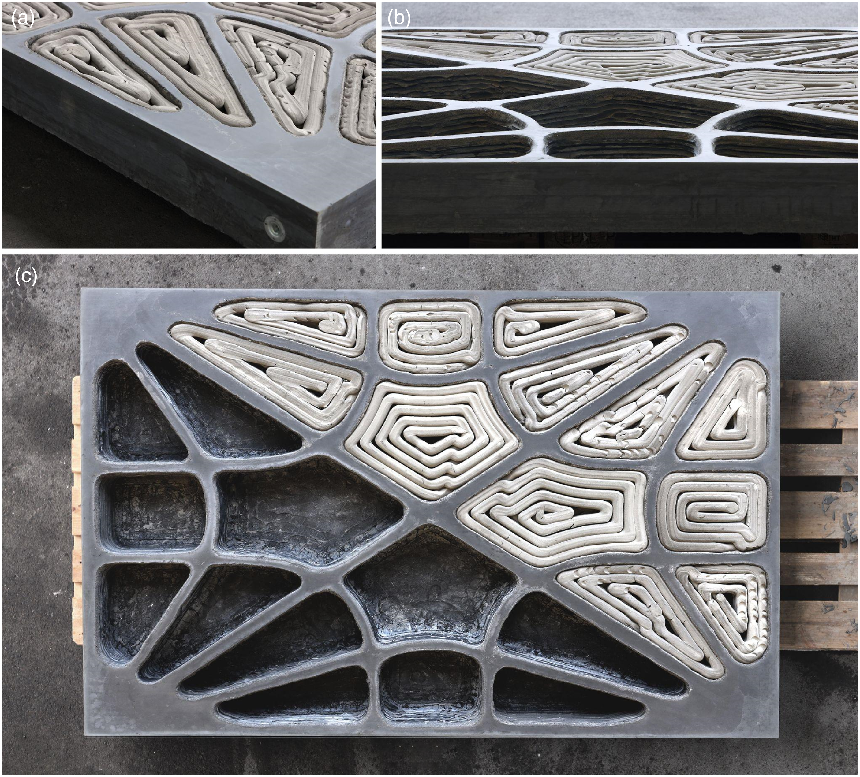
With the quick and easy assembly of the hardwood frame and the placement of the printed foam elements, the casting preparation process started swiftly. In contrast, it took much time and effort to wet-sand seal the foam components. The risk of potential errors in the final formwork arrangement also rises due to this manual process. This could be enhanced by adding additional alignment details, like peripheral notches and more finely articulated print path geometries. Additionally, printed installation features like tunnels and cavities could be used to integrate subsystems.
While alkali activation is common for 3D-printed cement-free elements with low porosity, this study was the first to show that it also works for printing sustainable mineral foams. This method uses less energy than consolidation by sintering and enables the fabrication of larger pieces at lower densities, conserving even more material for the slab prototype. In addition, compared to any syringe foam extrusion system, the foam production and printing were both quicker. As a result, it represents a significant advancement over the earlier study. 7 To mitigate the effects of shrinkage and geometrical deviations, a tempered printing environment with relative humidity and temperature control may be proposed for future development.
In this study, the compatibility of F3DP with concrete could be shown, which also allows using conventional rebar as a reinforcement strategy. However, by substituting a more environment-friendly concrete mix for UHPFRC as the structural filler, the environmental effect of the final composite element might be further decreased. Cement-free, fiber-reinforced mineral foams with high density and compressive strength could be employed as a structural component. The resulting mono-material building component with hierarchically graded porosity would simplify recycling and further support circular construction.
Improving the precision of foam 3D printing
The results of the 3D scanning process showed that the prints had already deviated significantly from the intended geometry when they were freshly printed. As shown in Figure 2(a), deviations were primarily measured on the z-axis and ranged from −26.49 to −17.13 mm in the sample. Prints produced as a result are often 20 mm lower than the desired shape. Additionally, as shown in Figure 2(b), variations in the cured prints mostly occurred in overhanging regions of the layers with a balanced axial distribution between −3.12 and 2.34 mm in the shown sample. The average deviation of eight measured samples was −2.61 mm in the wet state and −0.45 mm in the cured state. This suggests that long-term shrinking only makes up a small portion of the total variances.
For processing the digital target geometry during print path generation, a one-dimensional pre-scaling factor of 1.2 was implemented in the direction of the z-axis. The results of the scans after implementation revealed a notable improvement in reducing the deviations of the new prints from the desired geometry. With peak deviations between −9.39 and −4.10 mm, Figure 8 displays the scanning results for an improved specimen. With a maximum variance of 5 mm, the resulting prints generally approached the correct height of the target geometry. Specimen with applied pre-scaling: comparison between fresh print and digital target geometry.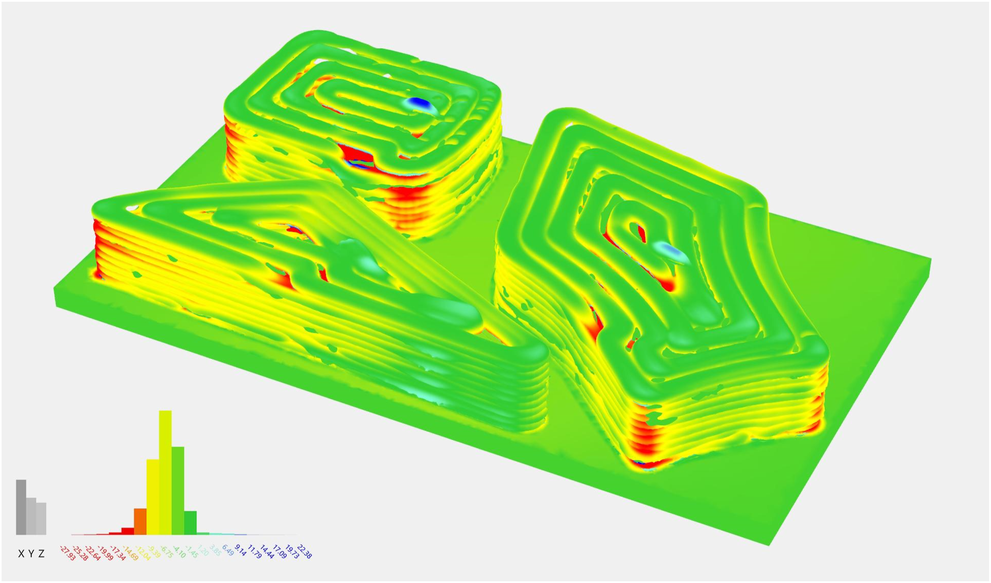
The methods for machine sensing for 3D printing mineral foam that were discussed can be improved in a number of ways in the future. To start, the 3D scanning technique for comparing uncured and cured print samples can be improved. The position of the target markers used by this technique showed significant deviations of up to 1.7 mm between the scanned specimens. Additionally, although a deformation during the curing cycle is unlikely, the mesh shape of the solid print base varied between the two scans. As a result, it is suggested that this method may be improved by comparing the raw point cloud data of a more accurate 3D scan procedure.
Second, based on the outcomes of the 3D scanning process, the pre-scaling technique used during print path development can be improved. Although the achieved decrease in geometrical deviations in the direction of the z-axis from −20 to +/− 5 mm is substantial, they can still be reduced much further. The pre-scaling technique was only tested with print parts with the same height. For any target height, the method’s dependability and robustness must be verified. Additionally, the pre-scaling technique can be used to scale layers along the x- and y-axes rather than only the z-axis. In print results, this might lessen the impact of tapering walls.
Third, real-time updates of subsequent layers based on camera tracking combined with image processing could be implemented to reduce dimensional deviations further. It is challenging to pre-compute toolpaths for each layer while 3D printing objects with unpredictable layer height evolution. This becomes even more of an issue when printing more intricate geometrical elements like branches and irregular voids. As a result, an integrated computational workflow between sensory feedback during fabrication and event-based path development for successive layers can be suggested.
On the other hand, if deviations and layer height evolution can be visually documented for various target geometries, such as double-curved walls, overhangs, and branching objects, the training of a statistical machine learning (ML) model may be useful for predicting the layer height evolution. The advantage over a conventional mathematical model, like the proposed vertical scaling factor, is that it could cover a much broader spectrum of target geometries and the non-linear material behavior of wet mineral foams. ML techniques can be used to optimize unstable printing processes and increase in situ control. 39 Particularly when printing with materials that shrink unpredictably, ML models can help to detect dimensional changes and counter them with mitigation routines. 40
Conclusion and outlook
This research provides a unique fabrication method based on F3DP for generating functional stay-in-place formwork for a lightweight composite concrete slab. The end product is an innovative building component that combines UHPFRC and sustainable mineral foams with the potential to reduce embodied carbon emissions and material use. Reliable F3DP, material processing, and environmental control methods are demonstrated. Construction-scale objects that are accurate enough for concrete construction could therefore be produced. For robotic F3DP, the digital workflow for print geometry processing and path generation yields consistent results for a variety of formwork geometries.
This research describes how sensing approaches can aid in detecting both short-term and long-term geometrical errors of print specimens to achieve near-net shape manufacturing. It was possible to demonstrate that only a few geometrical deviations occurred after manufacturing by 3D scanning and comparing print results. The print path design could be modified with a uniform pre-scaling factor to lower deviations from the target shape. Print accuracy should further increase with the use of feedback control during fabrication. Combining the previously discussed and presented sensing approaches offers methods for addressing complex material behavior during 3D printing and curing of mineral foams.
This novel fabrication method can positively impact the responsible and sustainable use of resources and energy. F3DP makes it possible to manufacture geometrically intricate foam components that were previously inefficient and cost-prohibitive. It allows to combine the geometric freedom of 3DP with the structural strength of cast material. This study has demonstrated that printed foam components are appropriate for stay-in-place formwork applications for concrete elements with geometries optimized for low mass, low material usage, and, consequently, low embodied carbon. Due to the reduced weight needing to be supported, the building part and the total load-bearing structure require less material, which minimizes the resources needed twice. Additionally, this weight reduction also has a favorable effect on construction logistics efforts.
Furthermore, bespoke foam components made with F3DP can be utilized directly as insulating construction components. The full range of building enclosures, including slabs, roofs, walls, and transitional components, can be targeted as an application. When it comes to components with intricate geometries, such as curved facade panels and thermally optimized walls, F3DP would save a significant amount of material. This application may help to construct buildings that use less energy in addition to the material savings described above. The proposed combination of advancement in materials, innovative manufacturing techniques, and geometrically optimized building components thereby addresses the responsible consumption of energy and resources for future sustainable construction.
Footnotes
Declaration of conflicting interests
The author(s) declared no potential conflicts of interest with respect to the research, authorship, and/or publication of this article.
Funding
The author(s) disclosed receipt of the following financial support for the research, authorship, and/or publication of this article: This work was supported by the Innosuisse Impulse program (Grant number 41,905.1 IP-EE), the ETH Research Commission (Grant number ETH-01 19-2), and the NCCR Digital Fabrication (Grant number 51NF40-141,853).