
Abstract
Precision of materialized designs is the conventional goal of digital fabrication in architecture. Recently, however, an alternative concept has emerged which refashions the imprecisions of digital processes into creative opportunities. While the computational design community has embraced this idea, its novelty results in a yet incomplete understanding. Prompted by the challenge of the still missing knowledge, this study explored imprecision in four digital fabrication approaches to establish how it influences the aesthetic attributes of materialized designs. Imprecision occurrences for four different digitally aided materialization processes were characterized. The aesthetic features emerging from these imprecisions were also identified and the possibilities of tampering with them for design exploration purposes were discussed. By considering the aesthetic potentials of deliberate imprecision, the study has sought to challenge the canon of high fidelity in contemporary computational design and to argue for imprecision in computation that shapes a new generation of designs featuring the new aesthetic of computational imperfection.
Keywords
Introduction
The issue of imprecision, reflected in the discrepancy between the design and its physical embodiment, is inherent to any design-to-construction process in architecture. Numerous architectural projects from the past and the present are appreciated for tectonic qualities that result from the architect having taken advantage of this imprecision. A recent example of such work is the Armadillo Vault at the Venice Biennale, in which the geometric differences between the digital model and the physical building blocks are negotiated through adaptive assembly strategies based on computing and traditional stonemasonry techniques, yielding a highly expressive design. 1
In the history of architecture, similar examples of such negotiations can also be found, albeit not involving the digital techniques but rather the negotiation between the hand drawing, the scaled physical model and the realized full-scale structure. Among these, Antonio Gaudi’s efforts to realize hyperboloid vaults, Frei Otto’s attempts with tensile and membrane structures, or Felix Candela’s work on ultra-thin parabolic shells are some of the notable examples.
Today, with the fast-paced incorporation of advanced digital modeling, computation, and fabrication techniques in architecture, a closer look at imprecision occurring between the digital model and its physical embodiment is important due to its generative potential—at the level of material performance and design esthetics. The new media, viewed not only as means for representing and handling complexity, but also as media for explorative inquiry, have the capacity to expand the current repertoire of imprecision handling strategies onto a new territory, in which imprecision becomes the central driver of the design process. Elevated interest in this new direction is already visible in current digital design research, taking the form of a paradigm shift coined as the second digital turn.2–5
This study proceeds along similar lines of thought by considering an artistic practice in which the inconsistencies between digital models and their material representations are sustained and amplified. A closer look is taken at four different digital fabrication techniques recently employed in architecture, to understand, capture, and characterize how imprecision and manufacturing errors occur in these techniques. The overarching purpose is to reveal how imprecision in digital design and production can be embraced and turned from a weak point into a creative opportunity.
One potential of the positive approach to manufacturing errors argued for in this study is its capacity to guide digital design and fabrication beyond the realm of high fidelity and ultimate precision, toward an esthetic practice marked by novel expressive forms and new types of tectonic design features. Such an establishment and acknowledgment of a new esthetic repertoire in the architectural practice can lead to yet another important benefit, that is, enhanced sustainability in building component production. If certain geometric, material, esthetic, and textural imprecisions start being classified as esthetically valuable instead of flawed, this can lead to a substantial reevaluation of current paradigms and quality assessment criteria in building component manufacturing. This can eliminate the need to discard some components from the production chain and therewith have economic benefits of decreasing the amount of construction material waste, saving the manufacturing time and maximizing the intellectual and technological effort related to customized digital fabrication processes.
Modern craft discourse and its stance on imprecision
To explain the relevance of linking imprecision and errors in digital fabrication with design esthetics, a broader discourse on modern craft needs to be considered. This discourse provides arguments for the value of imprecision in design production but also creates a foundation to explore alternative takes and territories within digital fabrication research in architecture. In this context, Richard Sennett, in his seminal book ‘The Craftsman’, defines the traits of good craft and offers hints for how, under certain conditions, even the use of machines could be regarded as good craft. 6 According to Sennett, craft is much more than a skillful, well-trained use of a tool. Rather, it entails a broader capacity, marked by the simultaneous use of the hand and the head, of skill and imagination, of combined problem solving and problem finding. A good work of craft is open ended. It shows signs of improvization and is underdetermined rather than strictly following a plan. Tactility, relativity, and incompleteness are the markers of good craftwork. Interestingly, Sennett chooses to critically discuss digital architectural design in this context. He urges the modern digital architect to avoid the risk of hands off design automation caused by digital tooling and encourages adapting a craftsperson’s way of thinking while using technology. He suggests that this could be achieved by the architect actively participating in the process carried out by a machine and critically learning from interaction with it. Sennett claims that open ended, hands on experimentation with machine workflows creates a condition for creative discovery and that making these workflows intentionally incomplete and indeterminate promises novel features to emerge in a design.
In a similar manner, David Pye, in his well known piece ‘The nature and art of workmanship’ supports the value of imprecision in design production. 7 He introduces the concept of workmanship of risk to place a clear esthetic value on the imperfections of crafted work, including work crafted with the aid of machines. In workmanship of risk, the artisan operating a machine deliberately takes a creative risk by tweaking the process in a way that departs from the industrial manufacturing standard, to achieve unanticipated esthetic results. The imperfections of the materialized design arising from this approach have high esthetic quality because they feature uniqueness and diversity so valued in handmade objects. This uniqueness and diversity counter the uniform and repeatable esthetic of designs materialized through carefully planned and precisely executed mass production. Pye also argues that the imperfections of material processing at the level of surface detail are as valid determinants of high quality as the expression of an object’s shape.
An akin perspective is also presented in a more recent craft theory by Howard Risatti who acknowledges the esthetic value of imprecision, discussing it from the standpoint of material imperfections. 8 According to Risatti, craft is characterized by the material being worked in harmony with its properties. If those properties also embrace irregularities of the material, the craftsperson negotiates around these by both skillfully as well as artistically incorporating them into the finished piece. In this way, the material irregularities turn into valuable esthetic design features.
The discourse on craft presented above provides a good argumentative foundation to perceive the unavoidable material imperfections as a creative advantage, by stressing their role in enhancing the uniqueness of the object and expressing the human effort and manual intervention behind it. However, it also enables to take a step further and provide an alternative perspective, in which one does not imitate the processes of handicraft in digital production but instead attempts to identify the imprecisions occurring in those processes and employ these for artistic exploration purposes. Exactly this way of thinking is argued for in this study. The suggestion is to validate the positive value of error and imprecision in the materialization process supported by digital tools by looking at inherent weaknesses in various digital fabrication techniques and exploiting those as a qualitative advantage.
A similar alternative approach to the value of craft, albeit from a different angle, has already been hinted in the digital architecture discourse. It was argued that the digital manufacturing process can reconcile the architect with craft in a new way. That is to say, the interaction of the designer with the material through the medium of a digital machine, instead of having a figurative or ornamental purpose as in traditional craft framings, can be much more open ended and based on material negotiation. 9 In this way, it can unleash the morphogenetic properties of the material and through this yield unanticipated tectonic design features with high esthetic value. 10
Existing research contexts and new knowledge contributions
To position this study within the existing contexts of architectural digital fabrication research, three themes of relevance are discussed below—material and tool agencies, intentional imprecision in computation and the aesthetics of imperfection. Within those contexts, the knowledge contributions of the research presented in this article are discussed.
Material and tool agencies
The interest of digital architectural design in material agency was sparked by the writings of Manuel DeLanda who claimed that matter has morphogenetic powers and should be employed for the purpose of giving form. 11 Such a generative framing of matter is significant for the study presented in this article, as it confirms the prominence of material behaviors in shaping the aesthetics of a design.
Architectural research efforts inspired by these generative potentials of matter successfully demonstrated that material behaviors do not need to be controlled to achieve meaningful aesthetic effects. One of the precedent projects is the P-Wall by Andrew Kudless, in which the dynamic behaviors of a flowing plaster mass cast into a flexible textile formwork were explored as a novel way of shaping the expression of an architectural partition. 12 Several studies extended this idea, by coupling it with the formative agency of tools. Flexible formworks partly capitalizing on spontaneous material behaviors and partly steered by means of customized programming of digital machines were introduced.13,14 In other studies, it was additionally proposed to combine the digitally-aided crafting of matter with its manual fashioning. 15 It was also demonstrated through physical prototypes and examples that customized digital fabrication setups triggering formative material behaviors enable an interesting approach to design materialization that extends beyond the straightforward manufacturing of a 3D model.16–19
From the above work, it can be concluded that enlightening but isolated perspectives on material and tool agencies have been presented so far. Namely, the previous studies focused on a single material combined with a single fabrication technique. What seems to be still missing is a comparative analysis of agencies in various materials, fabrication techniques and material crafting methods. The intention of the investigation presented in this article is to provide such a comparison by probing four combinations of different digital fabrication approaches, material typologies and manual material crafting strategies.
Imprecision in computation
Imprecision was explicitly addressed as a positive element of the computational design process at the conference of the Association for Computer Aided Design in Architecture ACADIA in 2018, in which it became the central theme of discussion. The introductions to conference proceedings challenged the preconception of computer-aided design as ultimately precise by boldly stating that it does not require precision and full dependency on computers. 20
However, although the research papers in the proceedings presented a wide array of approaches pertaining to imprecision in digital and material processes, the primary focus of the majority of the studies was on computational strategies of bridging the gap between the digital model and the physical piece. However, one study stands out by explicitly stating that digital imprecisions could be explored for aesthetic and creative purposes. 21 The authors demonstrate how intentional digital imprecision enables designers to step outside the disciplinary conventions and how it can become a generative design parameter rather than a factor to exclude for the sake of ultra-precise, literal materialization. However, because the mentioned study only discussed imprecisions in the context of architectural drawing and representation, it can be concluded that the phenomenon of imprecision at the level of materials, digital techniques and handicraft still remains undisclosed.
In light of this, the presented study seeks to contribute with an analysis of imprecisions inherent to a particular set of digital techniques and manifested throughout the entire design process—from initial digital concept creation to its final materialization. This analysis is done by following the computational translations and geometrical transformations that a conceptual digital blueprint model undergoes as it is materialized into a physical design instance. Additionally, examples of how the identified imprecision occurrences can be further explored to shape novel aesthetic features of the design are provided.
Aesthetics of imperfection
Finally yet importantly, a theme of significance for this study is that of the aesthetics of imperfection. In design research outside of architecture, such as product design research, the mistakes of the manufacturing process are highly valued. They are claimed to make the experience of the design object richer and more enduring. 22 If deliberately made visible in the design, they have a positive symbolic value, with an imperfect material object reflecting the imperfections of its human user and therefore contributing to her/his aesthetic enjoyment. 23 Through this positive approach to imperfection, the mainstream ideal of perfection is challenged by a novel concept of imperfect beauty. 24
In contrast to product design, in architecture only a few studies so far have embraced imperfection as a viable design feature. One study contributed with an important discussion on a theoretical level by arguing that the prevalent focus on digital precision eliminates the great potential of material agency. 25 Through this argumentation, the authors attempted to invite the architectural community to overcome the prevalent fear of imperfection in favor of creatively exploring it.
A similar line of reasoning was present in the prefaces of the proceedings of the already recalled ACADIA 2018 conference. The texts conveyed provoking claims that deliberate imprecision in computation could give rise to novel typologies of architectural form, surface and texture. 26 Despite this, the majority of the research papers in the ACADIA 2018 proceedings focused the discussions on computational strategies of handling material imprecisions rather than on its new aesthetic implications.
An outline of the aesthetic benefits of imprecision can, however, be found in architectural research on 3D printing. One of the first studies on the subject discussed how the errors of 3D printing using the layered material deposition technique can be turned into aesthetic opportunities. 27 This work was continued in studies that explored intentional errors in 3D printing, generated by deliberately tweaking a 3D printer’s G-code and hardware setup.28,29 Owing to these studies, knowledge on the aesthetics of imprecision in the context of 3D printing is now quite broad. At the same time, however, the aesthetic of imprecision for other fabrication techniques remains unexplored.
Consequently, in this context the contribution of the presented research resides in the characterization of the inherent aesthetic features arising from imprecision in four different fabrication approaches: CNC milling, vacuum thermoforming, 3D printing using the binder jet technique and robotic single-point incremental forming.
Research method and the design experimentation process
The described study was carried out within the methodological tradition of research by design, following its established criteria for research quality and validity.30,31 Accordingly, the central medium for accessing and producing knowledge were the processes of designing and creating digital and physical artifacts. 32 The analyses of qualities of the created designs, the analyses of phenomena accompanying their creation, as well as reflections upon them formed the basis for drawing research conclusions in a way considered valid by the architectural research community.33,34 In its entirety, the research process had a pragmatic purpose of deepening current knowledge as well as a strong experimental and speculative attitude, geared toward the provocation of the status quo through a discussion of alternative scenarios of making at the border of digital design and handicraft. 35
Consequently, a research framework consisting of four design experiments was devised to understand the phenomenon of imprecision and characterize its fundamental influence on aesthetic design features. Each experiment involved materialization of an object whose geometrical form originated from a common digital blueprint, representing an abstract, double-curved 3D form. The form was intentionally kept abstract, to limit and focus the experiments on issues of core concern to the study, therewith eliminating the need to handle a large number of complex design parameters, as would have happened if materialization of an architectural element with a particular function was considered. The blueprint also served as a stable frame of reference, enabling to trace and comparatively analyze the geometric and surficial discrepancies between the original geometry and its materialized instances.
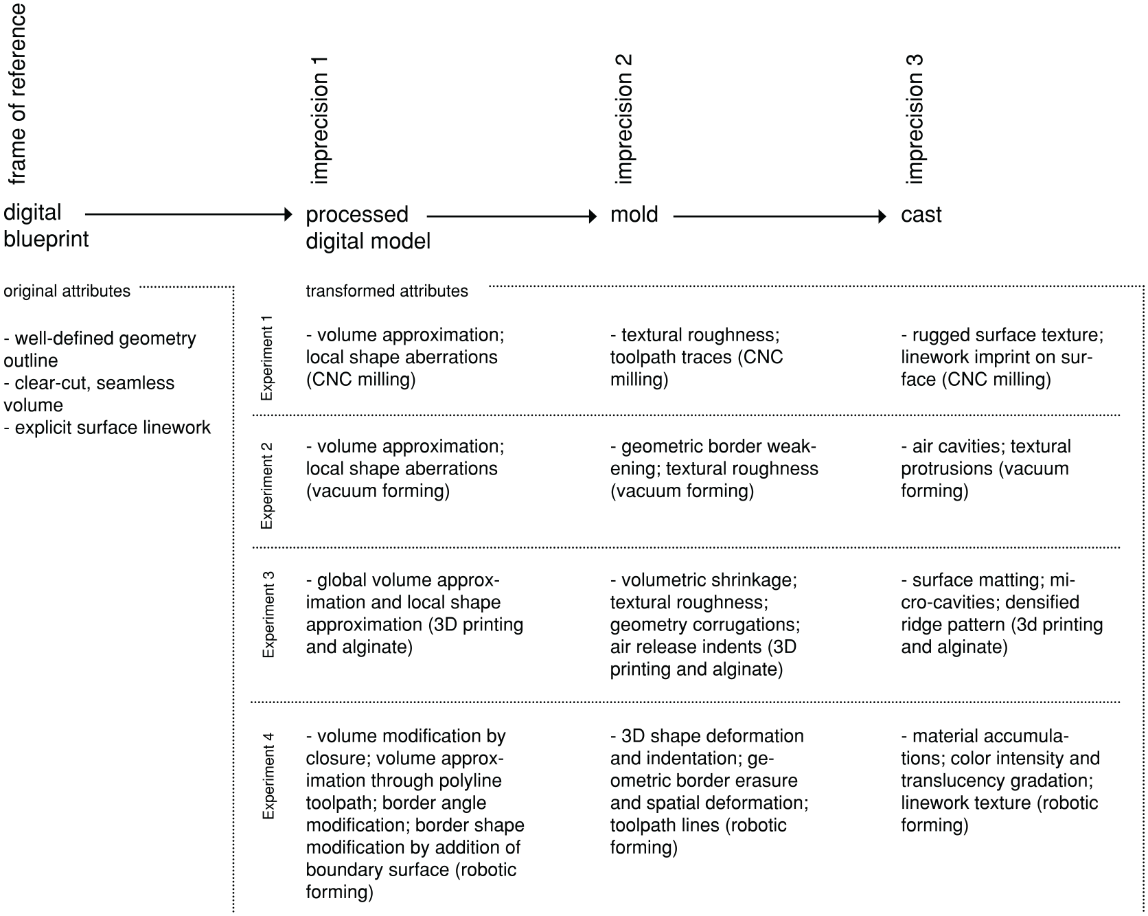
The conducted experiments probed four different digital fabrication techniques, materials, and crafting methods (Figure 1). Each experiment included three stages of transition from digital blueprint to physical artifact: digital processing, molding, and casting.
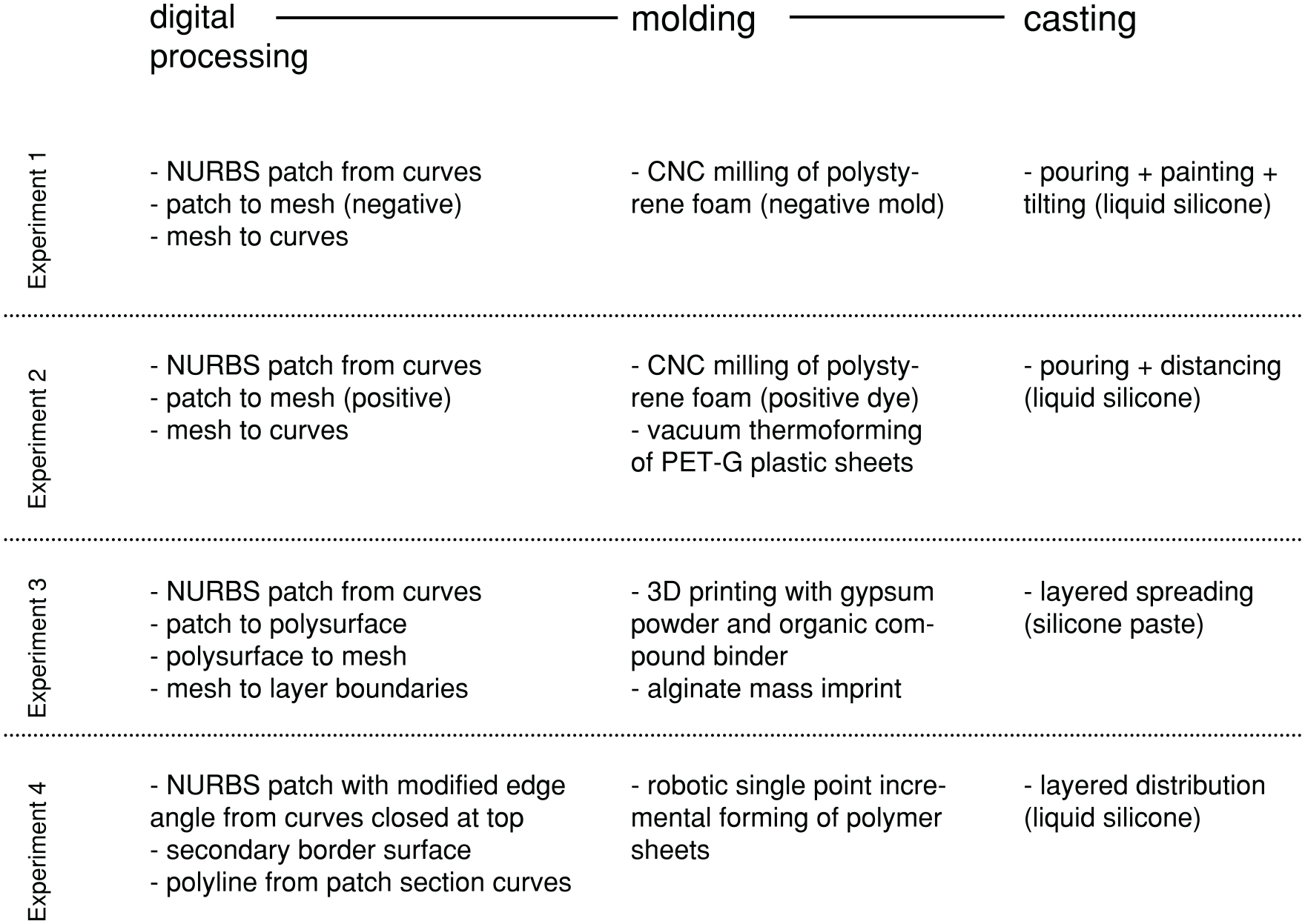
Framework for molding and casting experiments.
Each experiment began with the digital processing of the original blueprint model. The processing involved geometric alterations necessary for materializing the blueprint using the chosen fabrication method. Then, the processed geometry was used as input to fabricate the mold. In each experiment, one of the four fabrication methods (CNC milling, vacuum forming, 3D printing, and robotic incremental forming) was employed with one of the four different mold materials (polystyrene foam, gypsum, alginate, and a thermoplastic polymer PET-G). Each experiment ended with the casting of a silicone solution, in liquid and/or paste-like state, into the mold. The casting constituted the crafting part of the process, with silicone applied and manipulated by hand using various instruments and manual techniques.
Experiment 1: Imprecisions in materialization involving CNC milling
This first experiment began with the digital processing stage featuring a conversion of the original blueprint geometry into a representation required by the fabrication technique. Conventionally, CNC milling requires a mesh surface model to generate the machine toolpaths, while the blueprint was created as a NURBS (non-uniform rational basis-spline) model consisting of curves. To convert that model into the required representation, standard tools available in the 3D modeler Rhinoceros® 5 were used. Firstly, a NURBS patch was generated from the curves using a built-in Patch command, which fits a surface through selected curves. The patch surface is built by first finding the best-fit plane through the points sampled along the NURBS curves and then by deforming this plane into a double-curved surface that attempts to match the sampled points to the extent determined by a dedicated Stiffness parameter. The resultant NURBS patch surface was then converted to a triangular mesh representation, using a built-in STL (stereolithography) conversion function in Rhinoceros®. This triangular STL mesh representation was employed to generate the machine code in the firmware of the CNC machine. Therein, the model was sliced automatically into horizontal sections of equal height. The points marking the section borders constituted the final 3D data included in the machine code.
For mold fabrication, high-density polystyrene foam was chosen. Polystyrene foam was gradually milled away in horizontal planes, resulting in a negative mold. The parameters of the milling process were set within the machine code, with the slicing increment, step size, drill diameter, and tooltip shape directly affecting the precision, roughness, and quality of the mold surface.
The manual casting process involved pouring a liquid silicone solution into the mold and then carefully distributing it using a paintbrush. The painting was followed by multidirectional tilting of the mold. Tilting was employed to counter the gravitational flow of the liquid silicone toward the bottom of the mold and, through this, to equally distribute it on the mold surface. The tilting continued until the silicone began to coagulate.
Observed phenomena of imprecision
The first imprecisions occurred in the digital processing stage. The earliest ones arose during the computational conversions of the original NURBS curves into a NURBS patch and then into a mesh representation. In such conversions, some geometric data describing the precedent geometries is lost, as each converted instance is only an approximation of the geometry from which it was generated. 36 In this experiment, such computational loss of precision was indiscernible in an ocular way in the produced physical model. Therefore, for this particular experiment setup it did not significantly affect the aesthetic expression of the final design.
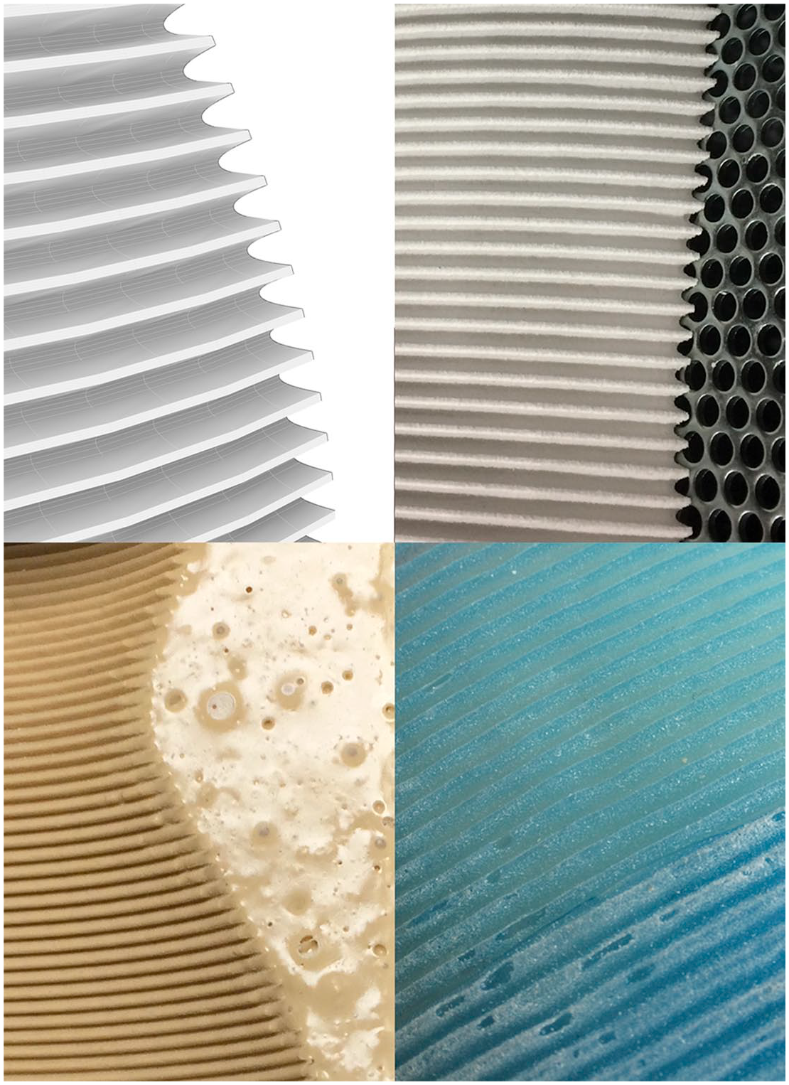
The second and more aesthetically profound occurrence of imprecisions accompanied the mold fabrication. Because the mesh model had been sectioned to produce the machine code, the final geometrical data for the milling machine consisted of selected points lying on the section curves. These points contained only a portion of the geometrical data from the original model, causing a significant departure from the initial geometrical description. This data loss left its marks in the fabricated mold. The mold acquired a stepped surface, with the traces of the CNC mill toolpath forming new features that were not present in the original design (Figure 2). These traces are further imprecise as they are visually evident in the flatter, less curved zones of the model and less visible in its steepest, most curved zones.
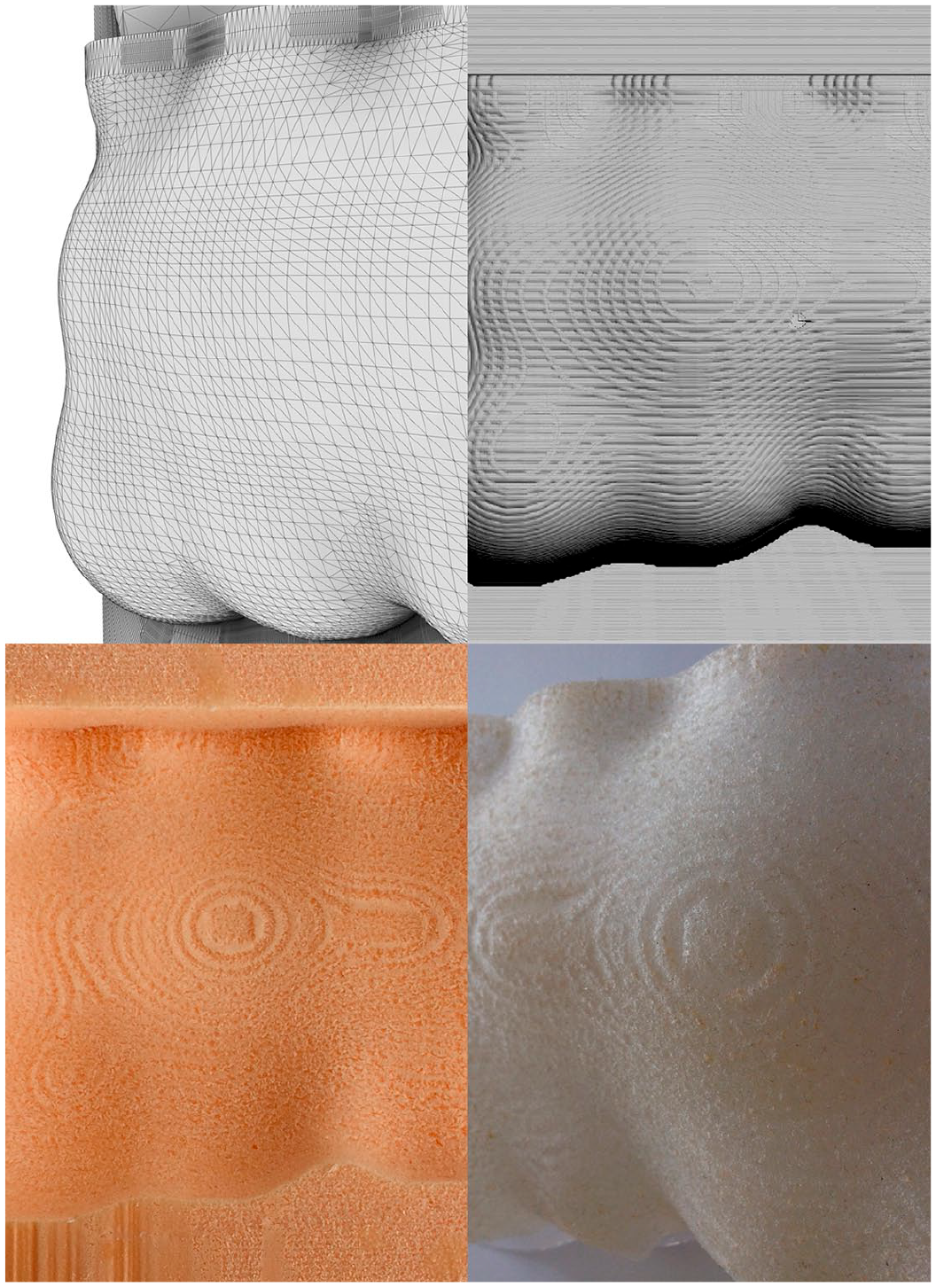
Differences and details arising from the transition of a digital model into a mold and into a cast in Experiment 1. Top left: Initial mesh. Top right: CNC milling simulation with toolpath trace indication. Bottom left: Imprecise toolpath and surface features in the milled foam mold. Bottom right: Resultant combination of linear and textural traces in the silicone cast.
During mold fabrication itself, further occurrences of imprecision were captured, related to material processing. Because in CNC milling the mold is produced by gradually milling away the material, imprecision also emerges from tool and material contact. The chosen mold material – polystyrene foam – is not ideally compact and hard. Therefore, its processing using a drill produced artifacts of roughness on the surface of the mold.
The final, although very subtle, occurrences of imprecision were discovered during the manual crafting of silicone into the mold. Because the silicone solution was being worked into the rough surface of the mold continuously using a paintbrush, the silicone cast did not only inherit an intensely rugged surface texture and the toolpath traces from the mold but also acquired an opaque and translucent appearance (Figure 2) – features that were not present in the ideally smooth and transparent digital blueprint representing the initial design concept.
Examples of further design explorations of the discovered imprecisions
In the stage of geometry processing, imprecision occurring due to geometric data loss in the NURBS to mesh conversions could be further emphasized by exaggerating the parameters of the computational processes of conversion – to produce the final mesh that departs from the outline of the NURBS precedent in a more dramatic, visually discernible way.
Further, in the step of mesh translation into machine code, the CNC milling parameters, such as sectioning increment, roughing and finish could be further manipulated to explore other toolpath curve distributions, which would then affect the surface expression and roughness.
In the stage of mold fabrication, other mold materials, such as various kinds of wood, polymers or lower density foams, could be employed to explore the effects of their hardness and density on the milled surface expression. This could potentially cause other textural qualities and surface artifacts to emerge, extending beyond the discoveries made in this experiment.
In the stage of material crafting, a broader repertoire of silicone application tools could be used to leave inherent traces within the material, for example, paintbrushes of varying shape and size, clay modeling spatulas, and palette knives. In addition, extra manual treatment of the silicone mass with these different tools could be explored when the mass begins to coagulate, to leave visually-evident traces within the cast.
Experiment 2: Imprecisions in materialization involving vacuum thermoforming with CNC milled dyes
In this experiment, the digital processing stage involved the creation of digital geometries needed for the production of positive thermoforming dyes. These dyes were chosen to be fabricated through CNC milling of polystyrene foam. Therefore, the original digital blueprint was processed using the same workflow as in the first experiment. The differences were that now a positive geometry was created and that it was additionally duplicated and scaled down to produce a larger and a smaller dye.
In the stage of mold fabrication, the positive dyes CNC-milled earlier in the process were used as underlays for vacuum thermoforming. Two thermoplastic polymer sheets were heated and lowered onto the polystyrene dyes. Vacuum was activated, causing the air in between the dyes and the sheets to escape and making the softened polymer fold itself over the dyes. The process resulted in two molds that could be put into one another.
In the stage of casting, the silicone was poured into the larger mold. As soon as the solution partly coagulated, the smaller mold was placed inside, lifted upwards after a while and left in this position until the solution has fully cured.
Observed phenomena of imprecision
Identically as in the first experiment, the first occurrences of imprecisions were related to the digital model processing for CNC dye milling and then the processes of milling of polystyrene foam dyes. As the nature of imprecisions was similar to the one in the previous experiment, they are not discussed here.
The next occurrence of imprecisions was captured upon vacuum thermoforming of the thermoplastic polymer molds. The first discovered feature of imprecision was represented by the blurred border of the mold in relation to the outline of the dye. Another feature was a partial texture inheritance from the polystyrene foam dye by the polymer mold. This inheritance occurred imprecisely as well, becoming most defined only in the roughest points of the polystyrene underlay, with the rest of the polymer mold surface acquiring a smoother texture (Figure 3).
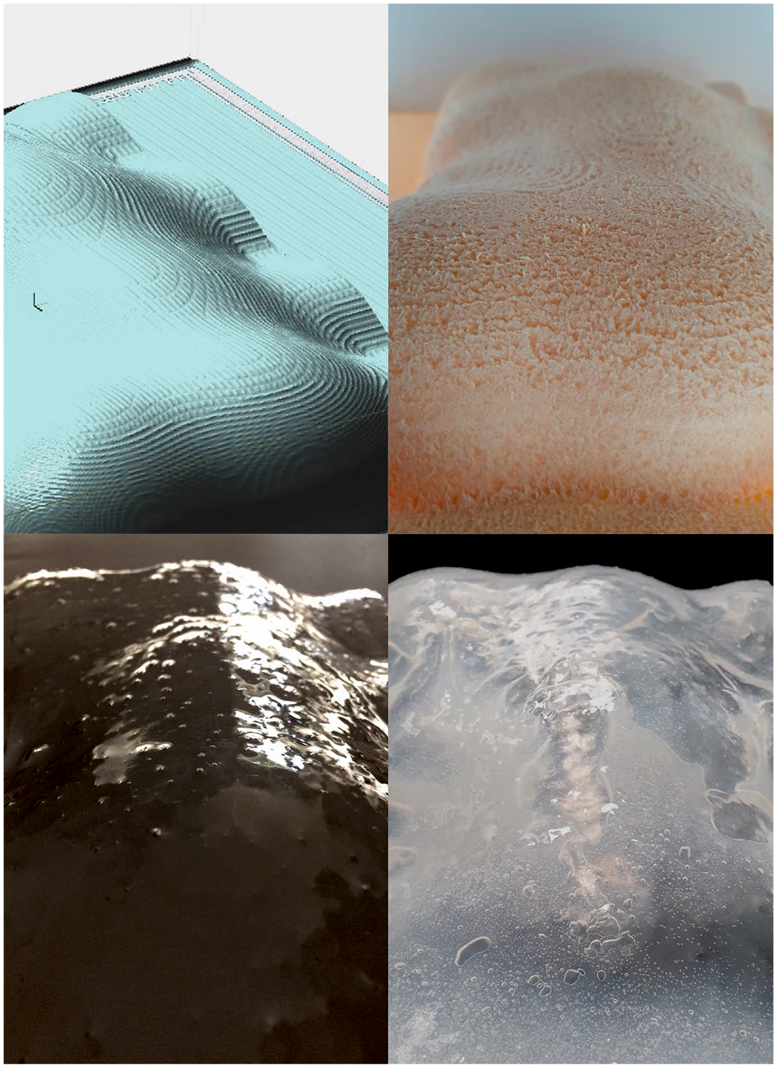
Differences and details arising from the transition of a digital model into a mold and into a cast in Experiment 2. Top left: CNC milling simulation with visible toolpath trace indication. Top right: Textural features of the polystyrene dye. Bottom left: The dye features incompletely transferred onto the vacuumformed mold. Bottom right: Silicone cast with air cavities and a coarse surface inherited from the polystyrene dye.
The final imprecisions occurred during material crafting, that is, manual mold parting. The parting caused the air to enter the still wet silicone solution, creating air cavities within the mass that were unplanned in the original design (Figure 3). The cast resulting from the parting was imprecise also because it acquired variable thicknesses that did not exactly follow the distance between the molds.
Examples of further design explorations of the discovered imprecisions
In the stage of digital processing, the inaccuracies arising from the approximation of the mesh model into a stepped toolpath representation could be harnessed to customize the milling process by creating a continuous feedback loop between the digital model, the toolpath representation and the features of the physical model. In particular, the phase of toolpath creation, instead of being done in the slicer firmware of the CNC machine, could be performed directly within the 3D modeling environment, using parametric aids such as Grasshopper® in Rhinoceros® 3D. This would allow to parametrically define the toolpath from the bottom up instead of relying on its automated generation. Such a custom toolpath design could form a basis for outputting the machine code directly from the parametric environment, using dedicated plugins or custom programming in, for example, Python.
In addition, if offline or real-time sensing of the milled surface features, for example, roughness or local curvature, were employed, then the numerical data from such surface inspection could be incorporated in the parametric script to define the shape of the toolpath curve and even adapt it in real time during milling. This could open up a vast space for explorations that could directly affect the outline, positioning and other features of the toolpath curve. If a 6-axis industrial robot would replace the 3-axis milling machine, this exploration could become very sophisticated in terms of the 3D articulation of the toolpath marks on the milled surface, which could now be processed from many directions in space. Secondary and tertiary milling rounds could be designed, based on 3D scanning data representing the surface milled in the first round. The surface features of this 3D scanned representation could then become an additional source of numerical data, employed to define the parameters for the second and third rounds of milling. In this way, the final dye produced in such a process could gain new surface features generated based on its own local surface imperfections translated back into the toolpath model.
In the stage of mold fabrication, one could tamper with the vacuum thermoforming process parameters, such as the heating time, temperature, and the moment of vacuum application. Changing these parameters would affect the level of material agency of the thermoformed polymer, affecting the definition of the geometry border by making it either more or less defined. Tampering with these parameters could also cause the emergence of new artifacts on the formed plastic surface, such as wrinkles and webbing that could form interesting additions to the surface expression. Moreover, the surface of the CNC-milled dye could also be manually crafted by sanding the dye surface, closing its pores with paint, or coating with putty, to explore how this affects the appearance of the vacuum mold’s surface and texture.
In the casting stage, the material agency of the silicone solution in its transition stages proceeding from liquid through partly coagulated to fully cured states could be explored more extensively. Through the diversification of the mold parting and demolding times for each of the cast sublayers one could affect the visual and in-mass properties of the final cast.
Another possibility for extending the material crafting explorations at the level of casting could involve the introduction of other materials left permanently within the silicone mass, such as polystyrene foam pellets (Figure 4), to manipulate the precision of the cast thickness in relation to the molds. Other potential crafting interventions introducing higher levels of imprecision could embrace the use of removable dispersed mold elements that would affect the mold thicknesses locally and affect its aesthetic appearance (Figure 4).
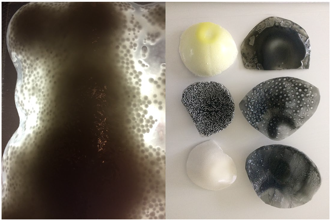
Examples of further explorations of imprecisions from Experiment 2, driven by material agency. Left: Polystyrene pellets left permanently in the cast to cause imprecisions in its thickness. Right: Esthetic implications of imprecisions accompanying the use of discretized mold elements, both permanent and removable.
Experiment 3: Imprecisions in materialization involving molding using a 3D printed dye
In this experiment, imprecision occurring at the magnified level of detailed surface design was investigated. Therefore, a fragment of the digital blueprint was worked on, and populated with new surface features – 3D corrugations.
The digital processing stage involved modeling a cross-section profile representing one corrugation. A fragment of the patch surface created in experiment 1 was sliced out and populated with this corrugation. The resultant NURBS model was then converted into a triangulated mesh representation required by the software generating the 3D printer’s machine code. That model was sectioned horizontally, with the section curves demarcating the approximate outlines of layers that would later on comprise the physical model.
The mold fabrication embraced the creation of a gypsum dye imprinted to produce the final mold for silicone casting. The dye was 3D printed layer by layer in the binder jet technique, with layers of gypsum powder fused together using a liquid bonding agent. The finished model was imprinted in alginate mass (Figure 5).
Differences and details arising from the transition of a digital model into a mold and into a cast in Experiment 3. Top left: Geometrical details of corrugations in the initial digital model. Top right: Corrugations of the gypsum dye with edges rounded in the 3D printing process. Bottom left: Corrugations further rounded, locally indented and dimensionally distorted in the alginate imprint. Bottom right: Silicone cast with matted surface and local geometrical precision loss at corrugations caused by the imperfections of the alginate mold.
In this experiment, the casting was done using pigmented silicone, to explore how the overlay of colors and transparencies affects the aesthetic surface qualities. To better control the respective sublayers of the cast and prevent their excessive blending, the silicone liquidity was reduced by using a hardening agent that turned it into silicone paste. The paste was then applied using a brush, layer by layer, gradually filling in the mold corrugations. While still wet, the excess of paste was taken away to create a smooth underlay for each of the next layers, also applied in the paste form.
Observed phenomena of imprecision
The first imprecisions occurred during the digital conversion of the corrugated NURBS model into a mesh model and then machine code required by the 3D printer. Similar as in the previous experiments, the geometric data employed to fabricate the physical model was reduced in relation to the original 3D data describing the blueprint. The model for the 3D printing process was an approximated, stepped version of the originally smooth NURBS precedent.
A second round of imprecisions occurred during mold fabrication. Firstly, the 3D printed dye model acquired visible layers on its surface and gained subtle surface porosities resulting from the roughness of the bonded gypsum layers. Further imperfections emerged during the preparation of the alginate mass from a mixture of alginate powder and water—air bubbles randomly distributed within the mass arose from mass mixing. The imprinting of the 3D printed dye into the alginate also yielded imprecisions. The layered traces of 3D printing became erased within the alginate while the rough texture of the gypsum was transferred into its surface. New features also emerged due to the rupture of the air bubbles in the alginate mass, causing the imprint to acquire small indents in its texture. Finally, a slight change of dimensions and proportions in relation to the gypsum dye occurred in the alginate mold due to the shrinkage of alginate upon drying. This affected the distances between the corrugations, which became smaller compared with those in the 3D printed gypsum dye.
The imprecisions of the casting stage embraced partial losses of surface continuity upon silicone demolding, in the form of randomly distributed surface chippings. At some places, bits of silicone became so strongly embedded within the alginate that they were left in it upon demolding, making the finish of the cast incomplete at those points. The silicone cast was also endowed with a new matte finish and a white tint, arising from the delicate roughness of the alginate (Figure 5).
Examples of further design explorations of the discovered imprecisions
In the digital processing stage, the surface corrugation pattern could be made more irregular, to make the proportion change due to alginate shrinkage more dramatic. This would affect the global appearance of the silicone cast and create an opportunity for further exploring both the surficial and cross-sectional properties of the cast, through varying its thickness, generating changes in surface roughness and generating gradual color transitions – all applied within the mass of one cast.
In the stage of molding, the air bubble rupture effect causing surface indents could also be amplified, for example, by intentionally introducing a larger number of air bubbles within the alginate mass through either mixing it mechanically or using an air pump.
In the stage of casting, the instruments for silicone application in combination with the material properties of the liquid silicone could be explored further. For example, ultra-precise application of liquid silicone could take place within the corrugations using a syringe or a high precision pipette. This could also be accompanied by partial blending of colors that would occur if silicone with varying color hues and translucency levels was applied and combinations of both silicone paste and liquid silicone were used in the process. 37
Experiment 4: Imprecisions in materialization involving robotic incremental forming
In this experiment, the intention was to explore imprecision in bigger models, closer to the architectural scale. Therefore, the digital blueprint was enlarged thrice and robotic fabrication was chosen as a medium for larger-scale materialization.
The digital processing stage involved the creation of a toolpath for the robotic process. The workflow from the first experiment was reused again, to generate a NURBS patch surface that would form the basis for generating the toolpath.
However, before toolpath generation, this patch needed to be altered to comply with the requirements of the SPIF process for the material chosen to be formed – PET-G polymer. That is, the steepness of the original geometry at its border needed to be reduced from 90 degrees to less than 75 degrees. The straight top edge cut-off also needed to be eliminated, by creating a curved geometry outline at the top. Finally, a secondary apron surface, inclined at 45 degrees, was added along the outer geometry border, to aid the forming of the steep geometry border.
After these alterations, the resultant patch surface was sliced with horizontal, equally distributed planes and smooth section curves were extracted. A dense network of points lying on those curves was then generated and used as a basis for the final polyline toolpath generation.
In the stage of mold fabrication, the process of robotic single-point incremental forming (SPIF) was carried out. A large PET-G polymer sheet was deformed incrementally, with the robot arm moving along the given polyline toolpath.
The casting process involved a pigmented silicone solution that was applied in liquid state so that it could flow and follow the outline of the robotic mold. The silicone was applied in several layers. Each time it was first poured roughly and then more accurately distributed with a flexible spatula and a paintbrush. Before entering the coagulation phase, the material was continuously moved from the lowest parts toward the most inclined top edges to avoid excessive accumulation toward the bottom of the mold.
Observed phenomena of imprecision
The imprecisions of the digital processing stage concerned, again, the translations between the different geometry representations. In particular, the conversion from the originally smooth blueprint curves to a jagged polyline curve defining the robot toolpath. Similar geometrical data losses took place as in the previous experiments, with the polyline curve containing only a portion of the original geometrical data from the blueprint.
An inherently new typology of inaccuracies also arose. It was due to additional model processing required by the polymer material. The blueprint geometry underwent changes of steepness at its border, together with an acquisition of a closure at the top and a secondary surface along the border. This caused the final input for the robotic process to differ quite dramatically from the original blueprint, with the most dramatic discrepancies concerning the geometry perimeter zone.
During the robotic forming process, the material agency of the mold material also played in quite significantly. The polymer underwent unanticipated deformations due to the internal strains induced by its forming. The geometric border was distorted in relation to the original blueprint. It became less sharply defined and spatially deformed, with the middle parts sinking down and the corners pushed upwards. In addition, the lowermost and least formed extremities of the geometry became pushed inwards, causing the emergence of local concavities in the globally convex form (Figure 6).
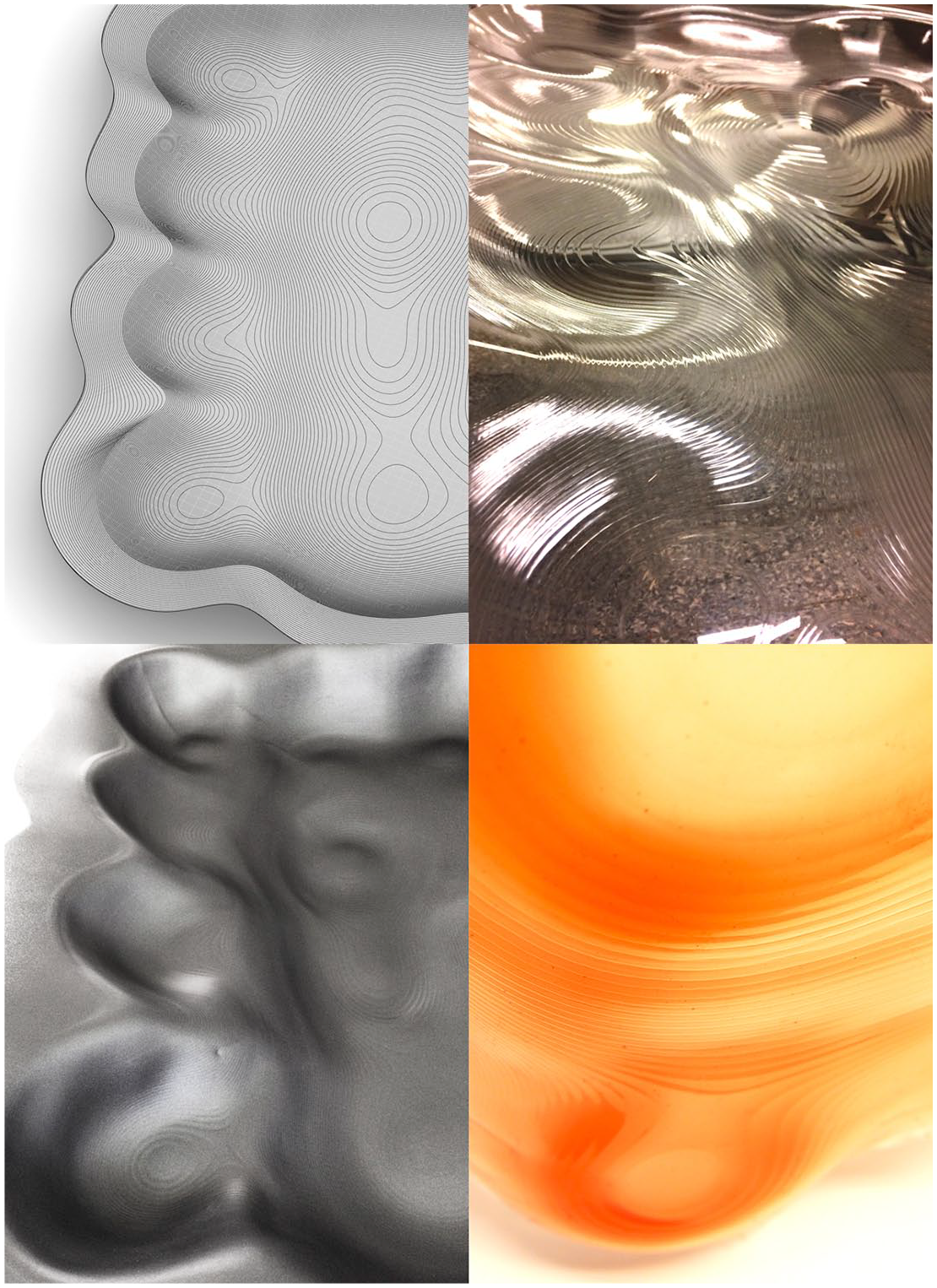
Differences and details arising from the transition of a digital model into a mold and into a cast in Experiment 4. Top left: Regular geometry of the toolpath for robotic incremental forming. Top right and bottom left: Geometrical imprecisions of the robotically formed mold – a deformed silhouette with local surface concavities and convexities. Bottom right: Aesthetic consequences of mold imprecision in the silicone cast – toolpath lines and varied silicone accumulations occur within the material mass, causing smooth transitions in material thickness, translucency, and color intensity.
The imprecisions of the casting stage were tightly related to the deformations of the polymer mold. Due to the presence of the unanticipated concavities of the mold, the thickness of the silicone layer became highly varied. The silicone was accumulated as a thicker layer around the convex regions and thinnest in the steepest and concave zones. This created an intriguing aesthetic effect of color intensity increase and surface translucency decrease, and therefore color and translucency gradation across the surface of the cast (Figure 6) – an effect that was not intended in the stage of digital blueprint creation. Finally, because the forming process was toolpath-based, the traces of that toolpath were embedded in the mold, consequently causing deflections on the surface of the cast.
Examples of further design explorations of the discovered imprecisions
The unexpected mold deformations and their consequences visible in the silicone cast can be explored further at the level of digital geometry processing, for example, by altering the course of the toolpaths of the robotic forming process.
The toolpaths can be fine-tuned locally to amplify the geometrical deformations of the mold in the stage of molding. For instance, the observed local concavity formation effect, occurring due to the inward relocation of the least formed mold parts, can be strengthened by intentionally enlarging, adding subtracting or shifting the areas in which it occurs.
In this way, in the stage of casting, varying silicone accumulation compositions can be produced using the same model as a point of departure (Figure 7). The aesthetic expressions of the silicone casts can be explored even further, for example, by applying silicone with varying color gradients within one mass to affect the optical perception of its depth. A detailed example of such design explorations is described in a separate publication. 37
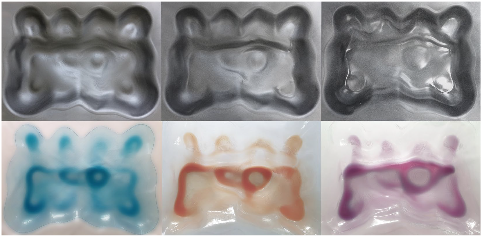
Example of further explorations of computational and material imprecisions in the robotic incremental forming context – manipulation of input geometry allows to generate three different surface compositions from the initial design.
Discussion of the findings
Types of imprecision
At the beginning of this inquiry, imprecision was defined as inexactness expressed as an observable discrepancy between the features of the initial design and its particular digital or physical representation. The conducted experiment series helped to refine this general definition by distinguishing and characterizing two kinds of imprecision accompanying the processes of digital fabrication: computational imprecision and material imprecision.
The identified computational imprecision relates to the level of digital data fidelity. In this study, it is defined as the variance between the data describing the original digital model and the data defining the digital representation of that model created for the purpose of digital fabrication. Such a representation is generated by either translating data from one level of resolution to another or by translating from one geometry representation, such as a NURBS model, to another one, such as a mesh model. In these translations, digital data describing the initial model is often lost and replaced by other data approximating the geometrical or topological description of the original model. While the algorithms that drive the processes of model data translation are predictable and computationally precise, their calculations produce a geometrical result that is an approximation or a lower-resolution representation of the original model. These approximations and lower-resolution models depart from the original dataset and, in this sense, can be qualified as being imprecise.
The material imprecision, on the other hand, relates to the level of fidelity of the physical model’s features in relation to the features of the digital geometry that was used to fabricate it. This imprecision is influenced by the properties of materials of the physical models but also by the ways and means of processing these materials (e.g. deformation, subtraction, addition of material; tool shape and diameter). The material imprecision is characterized by the occurrence of features and artifacts in geometry and texture that were not present in the original model. These features and artifacts can arise from the dynamic behaviors of materials undergoing processing or from the material properties such as density, porosity, brittleness, hardness, creep, and elasticity.
In this way, the notion of imprecision in computation and digital fabrication can be regarded as an umbrella term describing computational and material discrepancies – between the digital datasets occurring during the translation of the original model to a representation for fabrication purposes but also between the geometric and surficial features of the input model and its materialized version, represented by the mold and the cast made from that mold.
Imprecision characteristics in digital model processing, molding, and casting
The conducted experiments revealed that imprecision accompanies all three stages of the transition process from digital blueprint to physical instantiation: geometry processing, molding, and casting.
The imprecisions of digital geometry processing are represented by the geometrical differences between the initial digital blueprint geometry and the processed models enabling fabrication. Each fabrication method requires specific data inputs. Therefore, the original 3D data of the blueprint requires conversions by partial removal, replacement or completion with new data. This creates geometrical discrepancies and in certain cases can leave visible traces in the final manufactured design.
The imprecisions of the mold fabrication stage arise from the difference between the geometrical data used as input for the fabrication machine and the physical result in the mold. The mold geometry and/or the details of its surface diverge from the perfect shapes of the meshes or toolpaths driving the machine tools. The physical result differs due to the agency of the mold material—its inherent properties and behaviors unfolding upon its processing. The exact instantiation of imprecisions depends on the method of material processing accompanying a particular fabrication method.
The imprecisions of the casting stage are indicated by further geometric and surficial discrepancies between the mold and the cast and between the cast and the digital blueprint geometry. The nature of these discrepancies depends on the global geometry characteristics of the mold and the textural qualities of its surface, as well as on the physical properties of the cast material itself, such as liquidity and viscosity levels. In addition, the particular instruments and manual techniques employed to apply the cast material onto the surface of the mold affect the character of imprecision.
Esthetic attributes accompanying imprecision
The occurrence of imprecisions at the above three levels causes the emergence of four categories of new expressive attributes that transform the aesthetic appearance of the original design (Figure 8):
Attributes relating to form, shape and volume: Examples of new features: volume closure, deformation, shrinkage, and indentation.
Attributes relating to geometric boundary and silhouette: Examples of new features: boundary or silhouette weakening, erasure, spatial deformation, or surface steepness alteration.
Attributes relating to surface detailing and texture: Examples of new features: unanticipated surface roughness, toolpath traces, cavities, indents, and corrugations.
Attributes relating to optical properties: Examples of new features: graded glossiness, varying translucency, altered color hues, and diverse color intensities.
Summary of the aesthetic features characterizing the imprecisions discovered in the digital processing, molding, and casting phases of the four conducted experiments.
Further reflections on imprecision in computation and digital fabrication
The awareness of these imprecision levels and their inherent aesthetic traces opens up a vast space for extended design explorations. By tampering with imprecision phenomena on those levels, and by exploring them with different combinations of fabrication methods, mold materials, and manual casting techniques, the designer can generate a highly diverse pool of design alternatives, all produced from a single design blueprint.
An additional finding, interesting from the standpoint of how computational design is commonly perceived, is that the precision of digital modeling is not as evident as one may assume. The conducted experiments revealed that the produced digital models, such as NURBS surfaces, meshes, section curves, and toolpaths, are in themselves precise mathematically and geometrically. However, as soon as they are compared with the original digital blueprint from which they are derived, they paradoxically lose this precision, becoming approximations of the original shape.
A similar paradox can be identified during the digital fabrication of the molds. Here, mathematical precision is embedded in the digital input for each fabrication method, such as a mesh model or a polyline toolpath from which the final machine code is generated. The fabrication machine movements are also very precise, following numerical prescriptions defined in the code. However, once the machine tool makes contact with the molded material, that precision no longer holds. The often-unexpected properties and behaviors of that material come into play. Therefore, even if the machine movement perfectly follows the shape of its digital blueprint model, the mold material turns the outcome into an imprecise representation of that model.
Possible approaches to handling imprecision in architectural design and production
Although the focus of this study has been on the characterization of imprecisions in selected digital fabrication approaches, it is interesting to take a step further and consider how the discovered imprecisions could be handled in a digital design environment. One approach is to quantify, predict, and control imprecisions computationally. In this context, a study done at the Center for Information Technology and Architecture (CITA) introduced two rigorous approaches to monitoring and handling imprecisions in robotic incremental sheet metal forming of architectural elements. The first approach focused on in-process toolpath correction, based on online, distance-based monitoring of deviations between the input digital model and physical geometry, resulting in the correction of toolpaths for the subsequent forming rounds. 38 The second approach involved the prediction of deviations using a neural network algorithm that applies data of the forming process of the 3D scanned physical geometry to create a predictive model of inaccuracies that can be used for the correction of the original design. 39 An interesting feature of these two approaches is that they create a rigorous feedback loop between ideation, design, simulation, fabrication, and evaluation, enabling material imprecision to be expressed numerically and handled using computational means.
If a similar logic were to be applied to deploy and creatively steer the emergence of material imprecisions in the fabrication approaches in this study, these imprecisions could be quantified as follows. For vacuum thermoforming and robotic incremental forming, the imprecisions represented by geometrical deviations of the mold could be expressed as an orthogonal distance between the ideal geometry profile and the fabricated one. 40 Another way would be to calculate the changes in principal curvature for local deviation quantification and aggregate normal vectors for global deviation quantification.41,42
For the case of CNC milling and 3D printing, the most evident imprecisions, concerning surface quality, could be quantified using numerical surface roughness parameters obtained through measurement using optical instruments. Most simply, surface roughness would then be expressed as a deviation in the direction of a normal vector of a real surface from its ideal representation. 43 For small-scale features on surfaces, such as porosities experienced in the produced CNC-milled polystyrene molds and dyes, roughness could be quantified as the high frequency, short wavelength component of the measured surface profile curve. 44
The numerical data derived using these approaches could then be used for the prediction and creative steering of inaccuracy emergence, perhaps using as points of departure the approaches developed at CITA or other relevant strategies developed in manufacturing engineering.45–47 Which workflows and computational strategies would be best for executing an imprecision handling approach based on this logic is an interesting subject for future research.
A slightly different approach to imprecision handling would be a qualitative one, executed in a computational setting. Such an approach was proposed in a recent study done by one of the article’s authors. A method of artistic handling of fabrication errors was developed in the context of robotic single-point incremental forming, in which the fabrication imprecisions were only intermediately expressed numerically to support a qualitative visual analysis of the geometrical errors. In this case, imprecision emergence and amplification was meant to be triggered by the designer in the computational environment but in a way based on qualitative judgement of the physical fabrication result. 48
Both the quantitative and qualitative approach have their strengths and limitations. For example, the high-precision quantitative approach will allow for control of the result toward high precision while also requiring the development of custom algorithms and instrumentation that may not be readily available and easily graspable. The qualitative approach, on the other hand, offers an opportunity for artistic and intuitive design in the computational setting but it may be challenging to implement in the production of final building components, conventionally assessed from the standpoint of accuracy. Therefore, it seems that yet another solution would be to develop a hybrid approach that combines the previously mentioned rigorous quantitative methodology with the qualitative one. In such a case, the precision-oriented approach could be applied to design and fabricate portions of architectural elements requiring high fidelity, such as the meeting edges of cladding panels. The less precise, qualitative approach could then be used to shape parts of the design that do not require high accuracy, such as decorative features located in the inner zones of cladding elements.
Conclusion
This study has sought to demonstrate that imprecision in the computational design process can play a generative role in shaping novel expressive attributes of the design. The provided contribution embraced a fundamental analysis of how imprecision occurs in the transition process from digital blueprint to physical object for four different combinations of fabrication techniques, materials, and crafting methods. Examples and descriptions of emergent aesthetic features arising from imprecision were given, together with hints for how the discovered imprecisions could be explored further.
An important inference from this study is that precision in computational design cannot be taken for granted. Digital processes commonly considered as highly precise can prove not to be such upon closer examination. This observation implies that contemporary computational architectural design is in many ways already operating in the realm of imprecision and approximation. By expressing such an observation, the authors have sought to prompt the computational design community to develop further strategies employing imprecision as a creative design driver – to emphasize the currently emerging design exploration practice based on the joint artistic agency of designers, machines, and materials. Within this new practice, the elements of craft and uncertainty more legitimately enter the computational process. Digitally conceived and fabricated designs no longer need to literally mirror their digital blueprints and designers are no longer required to fully control the behaviors of architectural materials. The value of intentional imprecision lies in the new interactions between the digital tools, the crafting means and unpredictable material behaviors. These new interactions have the capacity to uncover new ways of architectural thinking and creation. Although geometric perfection and accuracy will remain valid design goals, a positive approach to imprecision expands them by reemphasizing the fundamental aspects of the design practice: exploring novel aesthetic expressions, exercising artistry and spontaneously engaging with the tools and the materials of making.
Thereby, the stance of the article’s authors toward imprecision is positive. The authors have directly witnessed the potentials of employing imprecision as a design driver in a recently completed architectural research project, in which this approach has allowed to broaden the solution space when exploring different design expressions for tactile interactive architectural interfaces. 49 From this experience, the authors infer that that imprecision plays an important role in extending the foci and expressive repertoires of computational design of today.
At the scale of a building, the application of guided imprecision implies the emergence of increasingly articulated ornamental features of building materials, which—if located at the eye and hand level—encourage visual and haptic examination by pedestrians or building users. A higher resolution of detail promises to yield a new generation of micro-scale architectural detailing that provokes much closer than usual examination of the architectural fabric, and a possibility to shape a new kind of a personal, immediate experience of architectural materials. Moreover, certain imprecisions, such as the geometrical ones observed in the process of incremental forming, could be applied at a larger scale, that of the building. This could be achieved for example by generating unique, varying geometrical designs for each panel in the façade cladding. In such ways, imprecision can contribute to shaping new expressions of buildings—both at the magnified level as well as at the urban scale.
Finally, perhaps the most important impact of imprecision studies in architecture pertains to their possible economic and ecological implications. For example, the positive outlook on imprecision could entail that some of the industrially produced building elements exhibiting imperfect features, which traditionally would be eliminated from the production chain, could be kept within the production loop. 50 This could have a profound impact on the amount of waste generated by the building sector, but also on the consumption of raw materials and energy. In addition, if those imperfection-generating industrial processes could be considered for mass-customization, with their errors harnessed creatively using computational techniques and custom-designed fabrication workflows, the positive effects of imprecision could become even more articulated. Moreover, many new sustainable but currently niche materials with an imperfect appearance, such as cellulose-based composites or biomaterials fabricated by biological agents and containing living matter, for example, mycelium and bacterial cellulose, could more strongly enter the market of esthetically-valued building materials.
Such benefits of favorable treatment of imprecision are already widely acknowledged in industrial product design, in which production defects, such as uneven texturing, non-homogenous coloration, incomplete mold filling and flow lines, are employed to personalize consumer products and create unique commercial branding strategies. 51 Influential industrial designers of the 20th and 21st century, such as Gaetano Pesce, have used imperfections to design products recognized worldwide. A well-known example is Pesce’s “Broadway Chair,” in which an imperfect blending of translucent, colored resin during the process of injection molding forms unique in-mass colorations that make each chair design one of a kind.
The above arguments reveal the importance of studies on imprecision in the context of architecture. With the current powerful toolkits of the architect, containing computational and digital fabrication media, the discipline can contribute new insights to the current state of the art. It can broaden the current knowledge on imprecision in manufacturing onto the phases of digital design, material experimentation and large scale construction.
Footnotes
Acknowledgements
The authors acknowledge the work of Karin Hedlund who assisted in the robotic fabrication processes accompanying this study.
Declaration of conflicting interests
The author(s) declared no potential conflicts of interest with respect to the research, authorship, and/or publication of this article.
Funding
The author(s) disclosed receipt of the following financial support for the research, authorship, and/or publication of this article: This work was supported by the Artistic Research Committee of the Swedish Research Council Vetenskapsrådet [grant number 2015-01519].