
Abstract
Fracture is one of the failure modes of a material or product which may occur during its manufacturing process or its usage. Fractography is the science and art of examination and analysis of the fractured surface. Texture and nature of the fractured surface provide valuable information on origin of a crack and crack propagation; thereby, it helps to understand the mechanism of fracture and facilitate to identify the likely causes of failure. This review covers an extensive study on various types of fractures of steel cord and bead wire which are primarily used in rubber composites viz tyre, conveyor belt etc. Different types of fractures studied include ductile, central burst, brittle, fatigue, torsion, corrosion, delamination and weld fractures. Fundamentals on specific characteristics of each type of fracture and their likely causes have been elaborately discussed Microscopic examination through scanning electron microscope (SEM) provides deeper insights of the fractured surface as well as microstructure of material. In addition to the fundamental aspects of fractures, examples of different types of fractured samples have been illustrated in this article. This focused review would be useful to the steel cord and bead wire manufactures as well as to tyre manufacturers for detailed failure investigation of material/product and thereby to take appropriate corrective measures.
Introduction
Fractography is a niche technique of examining the fractured surface of material or product which provides deeper insights of fracture mechanics. Knowledge and understanding on fractography helps to investigate the failure of material or product 1
Studies and research on fractography carried out by scientists and engineers covered a wide range of materials and products starting from structural material viz. Iron and steel 2 to polymer/rubber composites,3–11 ceramics and glasses.12–15
Present article emphasizes on fractography of steel cord and bead wire which are used in rubber composite products like tyres, conveyer belts etc.
Figure 1 Depicts the cross-section images of (a) truck and bus radial (TBR) tyre, (b) passenger car radial (PCR) tyre, (c) and conveyer belt describing major components and reinforcing materials Cross-section of rubber composite (a) truck and bus radial (TBR) tyre; (b) passenger car radial tyre (PCR); (c) conveyer belt.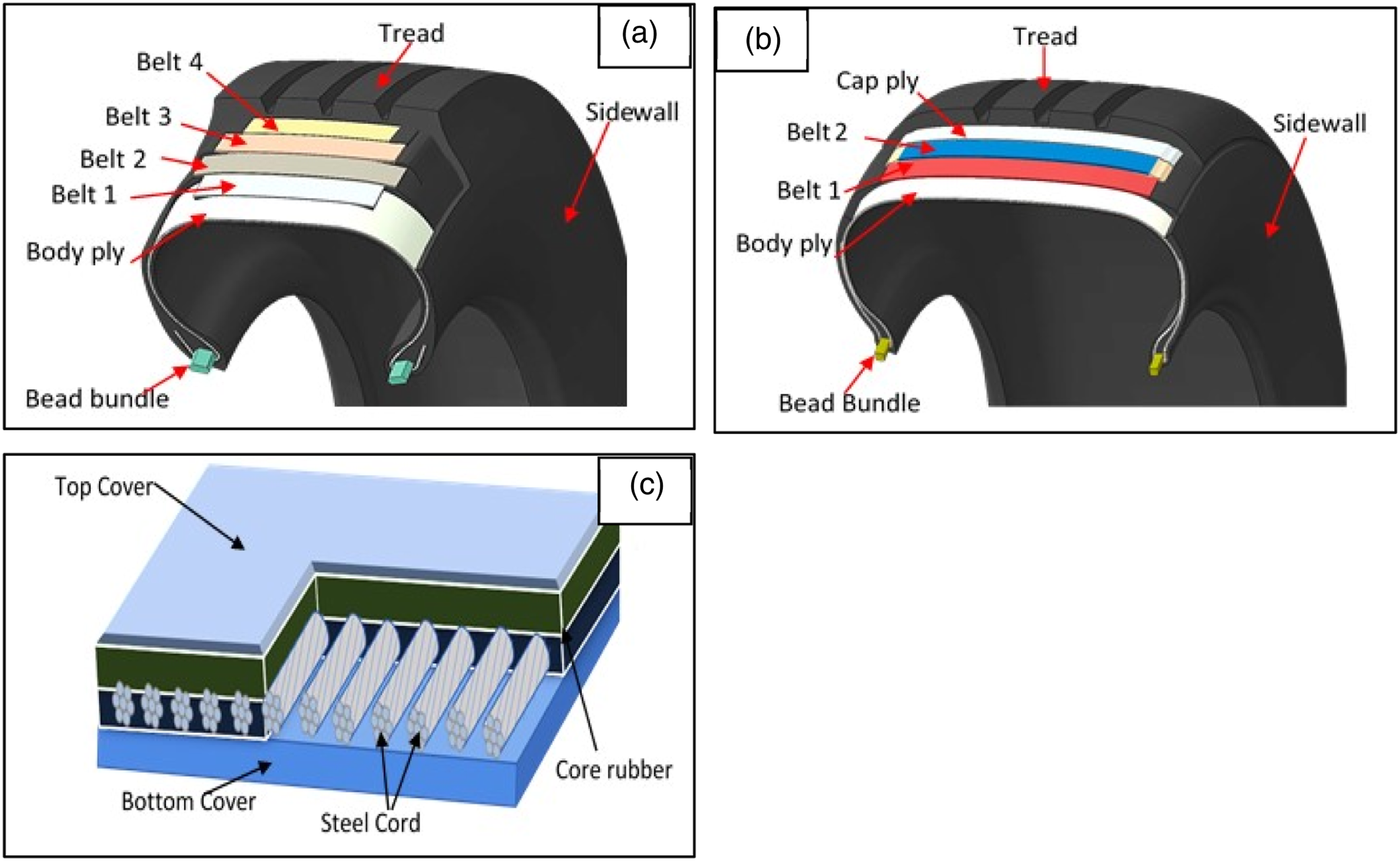
Used in these rubber composite products. 16
As depicted in the Figure 1, bead constitutes the stiffest part in the tyre which is fitted on the rim of a vehicle and therefore, it is used in all types of tyres. On the other hand, steel cord (made out of high carbon pearlitic steel filaments), is primarily used in “radial” tyres, as belt.
17
In case of TBR tyres, steel cord is also used as body ply. High tensile strength, modulus with required ductility are the key properties of steel cord required for tyre application.17–19 Figure 2 depicts the typical images of “brass” coated steel cord and “bronze” coated bead wire. Since these materials are used in the rubber composite products, “coating” is essential to achieve the desired level of adhesion between metal and rubber, which gives the integrity of the composite during service. (a) Brass coated steel cord (3+9+15x0.175+0.15); (b) Bronze coated bead wire (1.83 mm).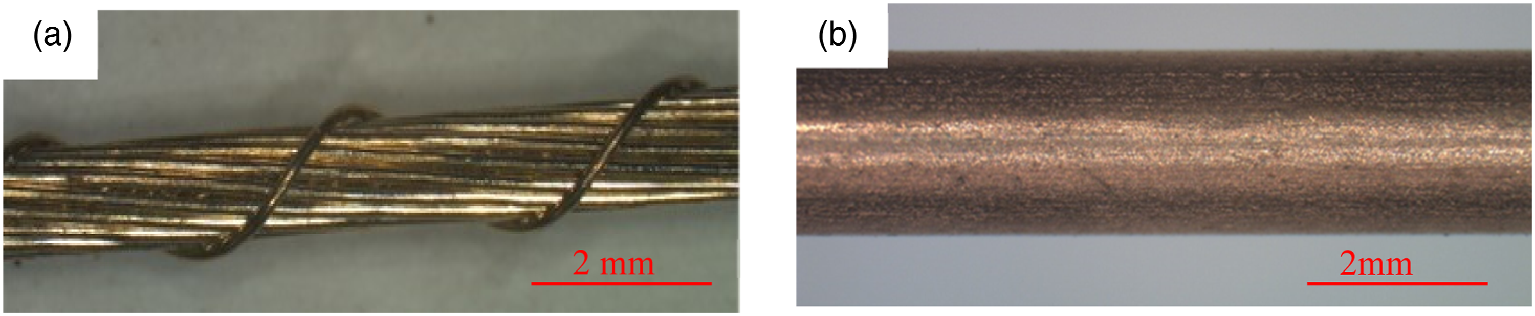
Steel cord and bead wire together constitutes the “skeleton” of tyre which provides its structural durability. It plays an important role to meet the key performance requirements of the tyres viz. Load carrying capacity, driving response (accelerating, cornering, braking) and dimensional stability (uniformity, ride and handling)
Tyre is a high-tech composite, which is designed to withstand severe dynamic loading under hostile environmental conditions. Major failure modes during service include belt separations, concussion/burst, through cuts, zipper, bead area failure, turn-up separation, etc
20
as shown in Figure 3. Few of these tyre failure modes (through cut, zipper, concussion, star burst) are associated with fracture of steel cord. A detailed examination of the fractured surface provides valuable information on the likely causes associated with these types of tyre failures.21,22 (a) Showing the typical belt separation failure mode of tyre; (b) Through cut; (c) Ply pull-out; (d) Concussion type of failure; (e) Zipper type failure; (f) start burst sidewall.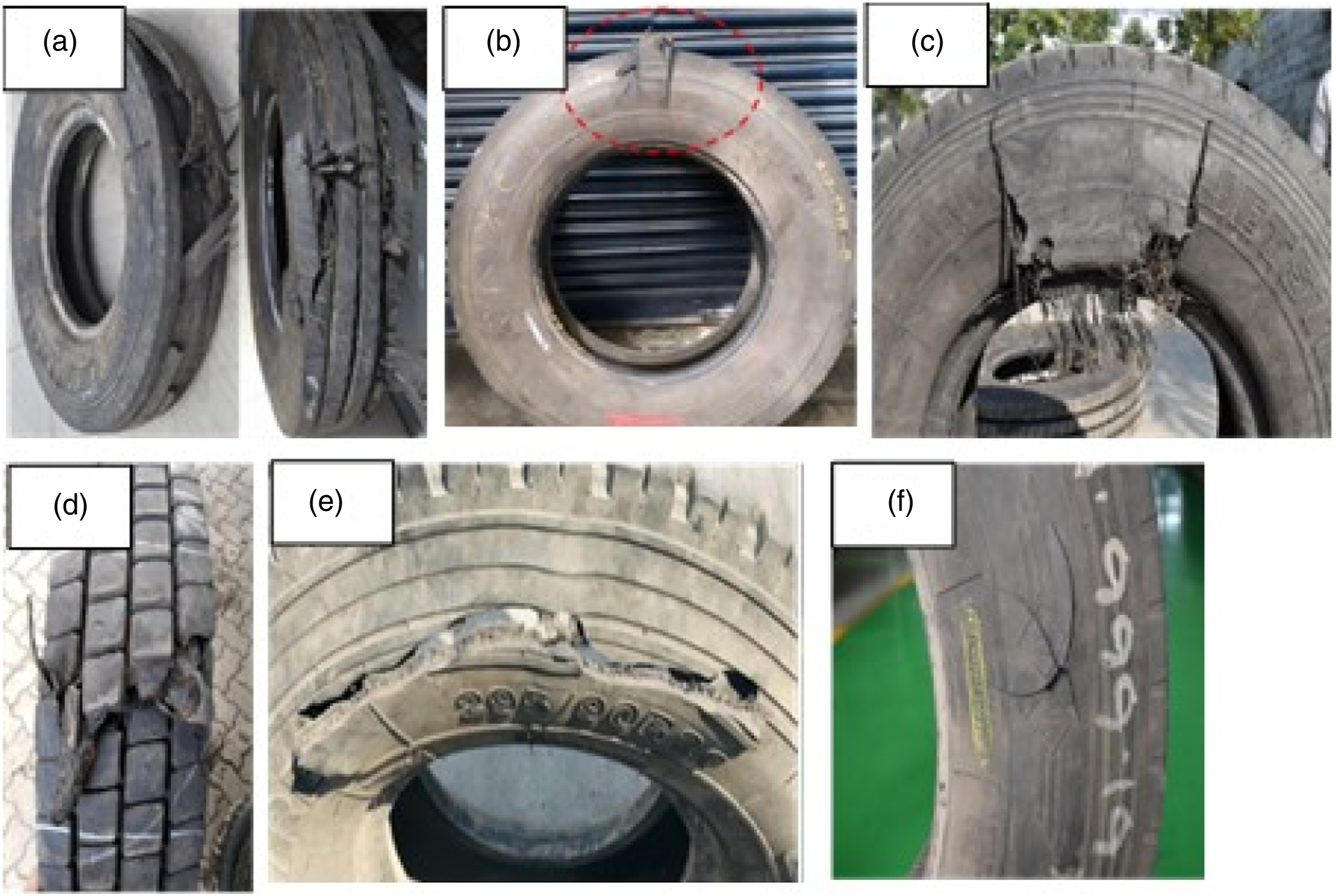
Breakage/fracture of steel cord or bead wire may also occur during its manufacturing process. The characteristic nature of the breakage at the rupture point differs from case to case depending upon the causes which are mostly related to either metallurgical or manufacturing process conditions. This review illustrates theoretical aspects of various types fractures and related microstructure/morphologies of steel and also provided examples of samples having different types of fractures. Hence, a deeper understanding on this subject will help to identify the causes of fracture occurred in actual scenario and thereby to take corrective measures.
Fracture analysis through microscopic technique
Microscopic studies provide valuable information on crack initiation, propagation and ultimate fracture.23,24 Generally optical microscope with magnifications in the range of 8x to 80X is used for initial examinations of the fractured surface. For deeper studies on the fractured surface morphology higher magnification viz (100x to 20,000X) is required, where scanning electron microscope (SEM) is widely used. Images (optical/SEM) of various fractured samples have been illustrated in subsequent sections.
Sample preparation is an important aspect for microscopic analysis. For failure analysis of the rubber composite product like tyre, it requires skill and expertise to extract the cords from the composite and then to remove the rubber around the fractured cords without damaging/contaminating the surface. It is advisable to clean the dust/rubber particles from the fractured surface in ultrasonic bath (with ethanol) prior to microscopic study.
Different types of fractures
Subsequent sections describe in details about different types of metal fractures, its mechanism both in the form of physical and morphological phenomenon. It also includes the relevance of each of these type of fracture with reference to manufacturing process of steel cord/bead wires and service failure of tyres.
Ductile fracture
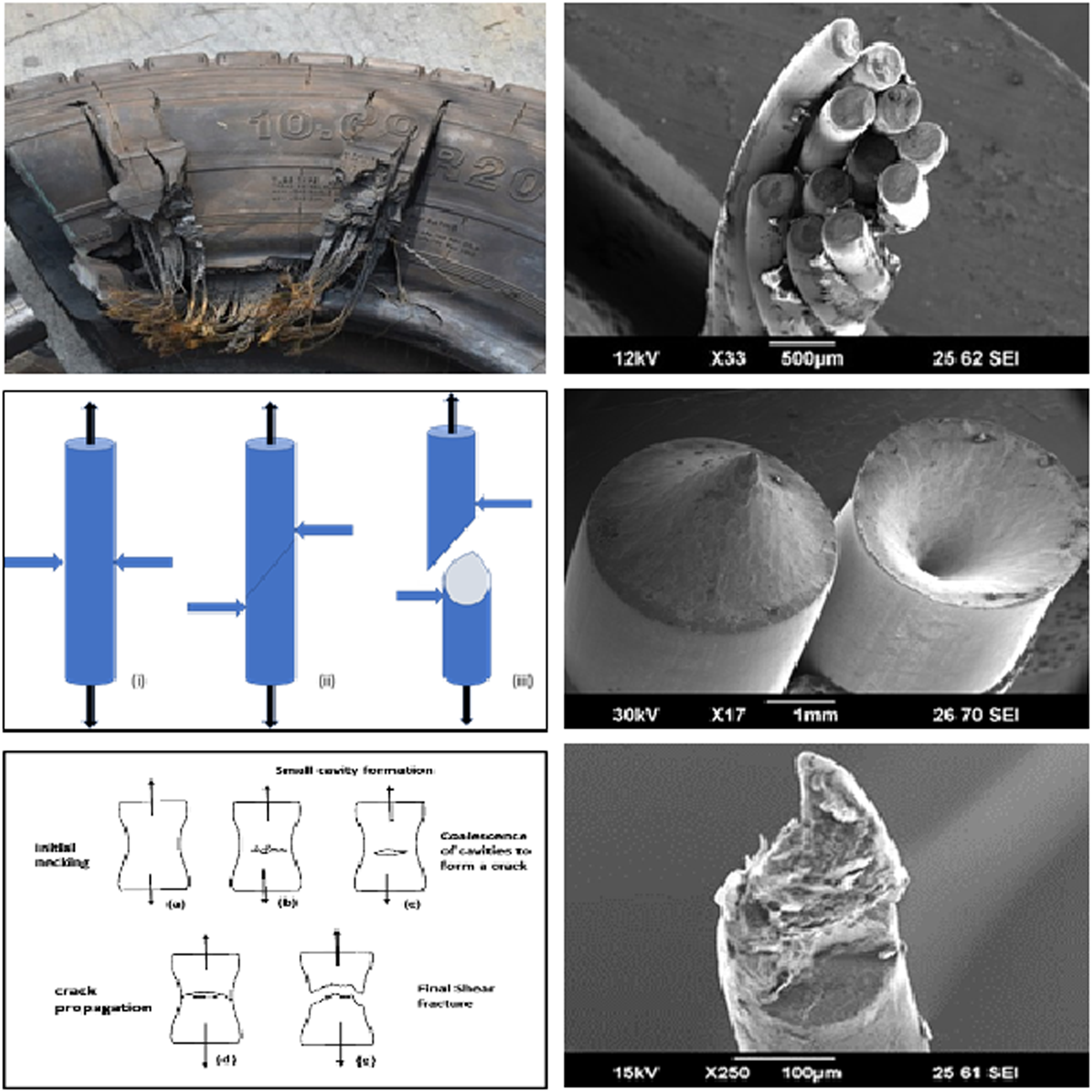
Ductile fracture occurs due to axial tensile loading; wherein necking starts beyond the elastic limit prior to the ultimate fracture.
25
One end of the fractured material looks like a cup, whereas another end appears as cone and popularly called as cup and cone fracture. Tensile testing of steel cord/bead wire in universal tensile testing machine gives ductile type of fracture. Figures 4(a) and 4b refers to the fractured ends of bead wire and filament of steel cord after tensile testing; broken ends looks like cup and cone. (a) Broken ends of tensile tested bead wires;(b) Broken ends of tensile tested steel cord filament;(c) Magnified image (10,000x) of the fractured surface of bead wire;(d) Magnified image (10,000x) of fractured surface of steel cord filament.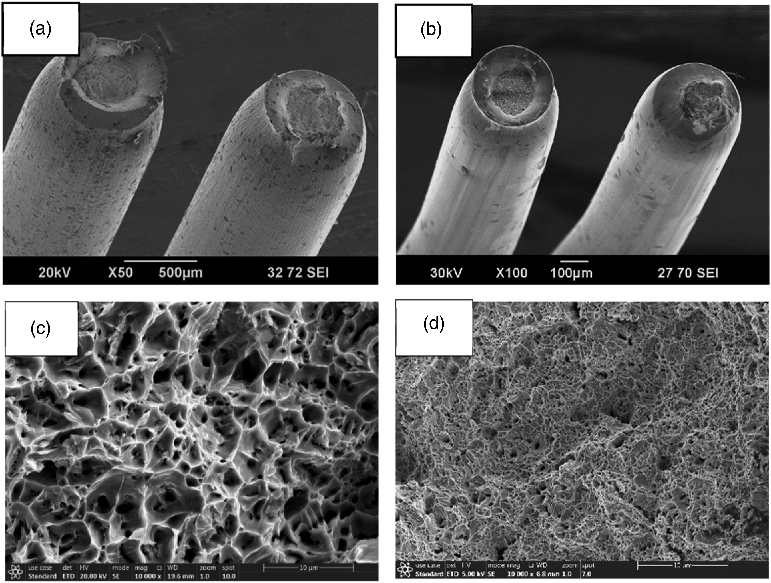
Figures 4(c) and (d) depict the magnified SEM images of the fractured surface of bead wire and steel cord filaments respectively. The morphology of this fractured surface seems to have a presence of multiple micro-voids. This kind of morphology is known as ‘Dimple morphology”. 26
During manufacturing of bead wire and steel cord filament, gradual reduction of diameter of wire happens through wire drawing process.27 Breakage of wire during the drawing process may occur because of tensile load (due to higher drawing/take-up speed); the broken ends looks like cup and cone indicating ductile type of fracture. 26 However, wire breakage, if occurs because of inappropriate microstructure or due to the any other defect, that may lead to other types of fractures, which are discussed in the subsequent sections.
In service failed tyres, different types of fractures of steel cord are observed which will be discussed in this article. Detailed analysis of service failed tyres indicates that “ductile type” of steel cord fractures are generally not associated with root causes of the service failure, rather it happens as a consequence of some primary issues. For example, some of the steel cords in the belt/body ply may get damaged due to through cut by nail or any sharp object. Nature of the steel cord fractures at this location (primary fractures) are shear type (will be discussed in 3.5 section). Load bearing ability at the adjoining area of the through cut region became weaker and thus susceptible to tensile failure against any impact under overloading conditions. One such case of concussion failed TBR tyre is depicted in Figures 5(a) and (b), where body ply as well as belt cords got fractured. The type of fracture found to be ‘shear type at the external impact location (refer Figures 5(c) and (d)); whereas, adjoining area found to be ‘ductile type’ of fracture (refer Figures 5(e) and (f)). (a) Zipper type of failure with external impact on the tyre; (b) Failure area after tread removal showing two locations i.e impact location and zipper failure area; (c) & (d) Shear type of fractures in steel cord filaments extracted from impact location; (e) and (f) Ductile type of fractures in steel cord filament extracted from zipper failure location.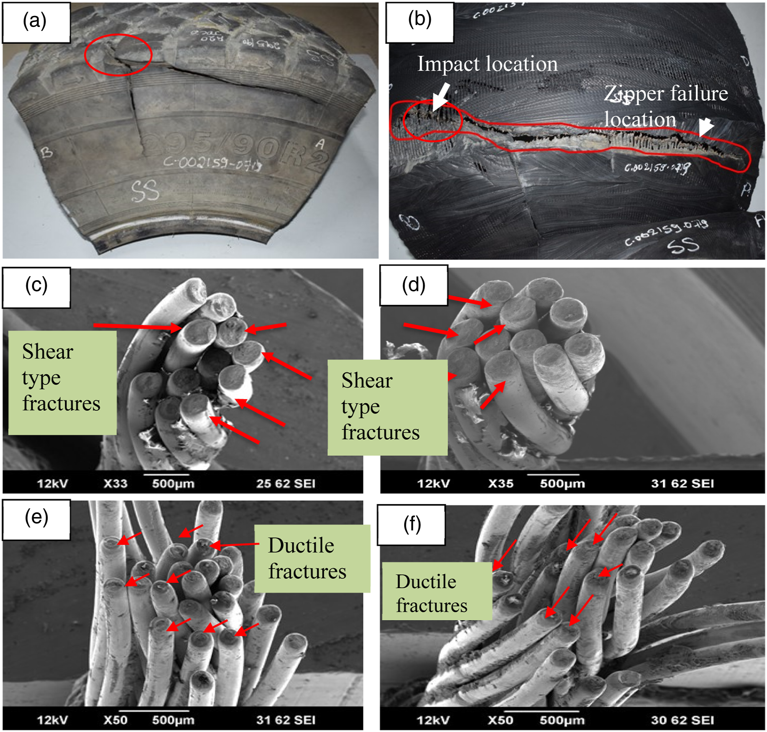
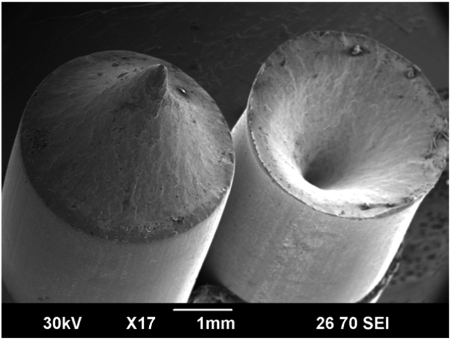
Central burst (pencil point) fracture
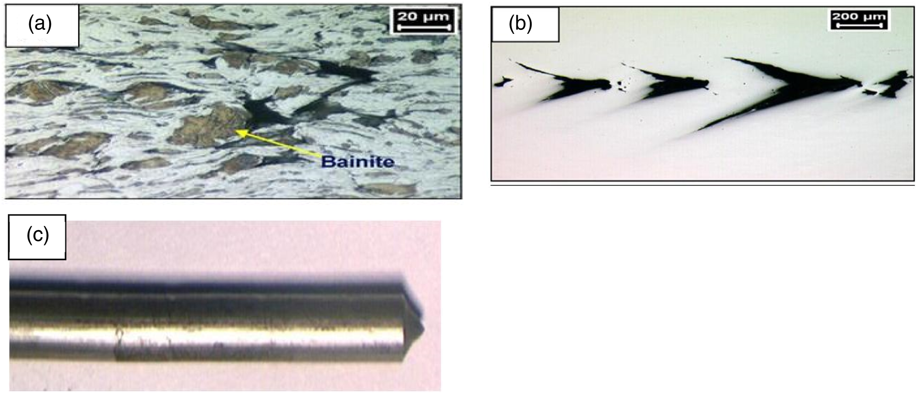
This type of fracture looks pencil point shape at one end and a matching conical hole at the other end with an angle of approx. 45° to the axis of the wire. Because of the typical shape of the broken ends, this type of fracture is known as central burst or pencil point fracture. This kind of fracture doesn't have necking unlike the one observed in ductile type of fracture. The ‘central burst’ type of fractures mainly observed during the manufacturing process of the wire. Figure 6 depicts SEM image of the fractured ends of the wire (5.5 mm) which happened during its manufacturing (drawing) process. Metallurgical defects in the wire is the major reason for this type of fractures. Metallurgical defects include hard phases like martensite, bainite or inclusion at the core of the wire which lead to central burst type of fractures during wire drawing process. Hard phase at the core and soft phase (base material) at the outer area creates inhomogeneity in the structure which leads to cracks at the core during wire drawing process due to difference in drawability within the wire structure. This mechanism is illustrated in Figure 7.28–32 Presence of inhomogeneous hard phases (bainite) in the wire drawing direction is depicted in Figure 7(a). Further wire drawing generates typical cracks at the wire core which looks like crow feet as depicted in Figure 7(b) these cracks eventually results into central burst type of breakage during wire drawing Figure 7(c). Typical central burst fracture of wire rod used for bead wire manufacturing. Optical images illustrated; (a) hard phase (bainite); (b) crack at the core during drawing; (c) leads to central burst.
29
Brittle fracture
Brittle type of fracture generally observed in metal due to its brittleness characteristics. It can be easily distinguished from the nature of the fractured surface. In case of the metal wire, the smooth fractured surface lies perpendicular to the axis of the wire as depicted in Figure 8(a). (a) SEM image of brittle fractured Bead wire; (b) Schematic diagram of trans-granular brittle fracture; (c) Schematic diagram of intergranular brittle fracture.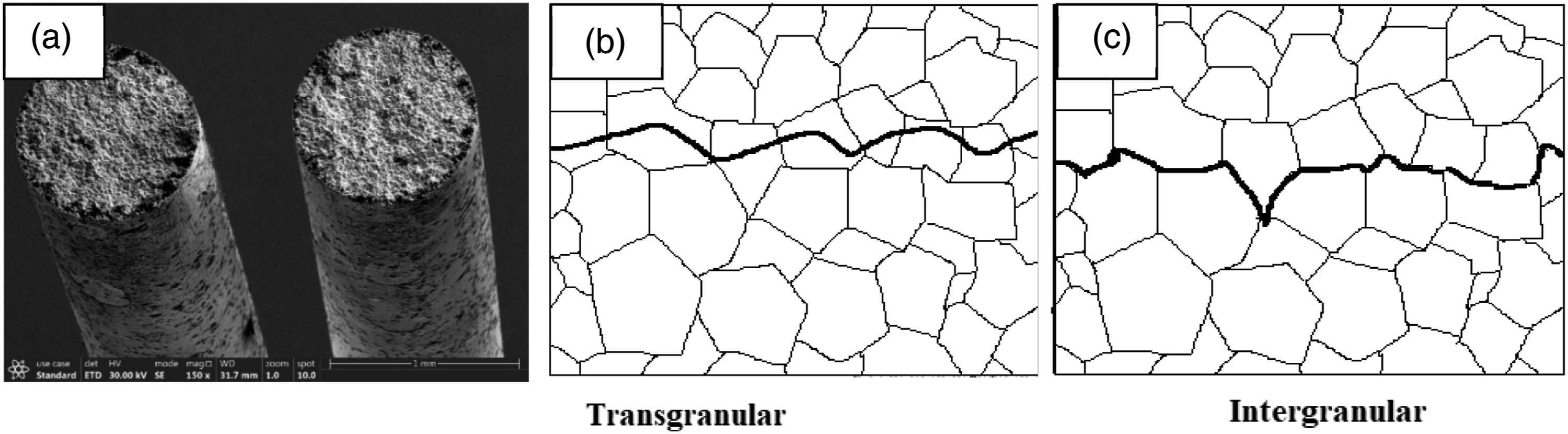
This type of fracture is unlikely to occur during product in service because of the adequate ductility of steel wire/bead wire. However, during manufacturing of bead wire/steel cord filament, brittle fracture may happen in any intermediate process. This is mainly because of the defects related to microstructure in the wire. For example, any hard phase (martensite/bainite), if present in the microstructure may lead to brittle type of fracture in the subsequent process. The causes for creation of martensite/bainite structure is mostly related to abnormalities in the annealing process, which is extremely critical to create the right type microstructure to facilitate drawing of the wire. 33
Fractographic studies on brittle fracture drew attention of many scientists. There are several literatures exist which illustrate mechanism and surface morphology of brittle fracture.34–37 SEM studies indicate that brittle fractures have surface morphology either trans-granular or intergranular as illustrated schematically in Figures 8(b) and (c). Intergranular type of fracture associated with the cracks propagates through the grain boundaries Figure 8(c).34,35 In case of trans-granular type of fracture, crack run though the grains Figure 8(b).36,37
In service failed rubber products like tyres, brittle type of failures is rarely seen either in steel cord or in bead wire. However, the knowledge and understanding on fractography and microstructure of steel helps in taking appropriate measures in upstream process.
Fatigue fracture
“Fatigue” is associated with repetitive or cyclic stresses experienced by any product in its service.
38
Fatigue resistance in terms of defect/crack initiation & subsequent propagation is one of the important characteristics of the material or the product during its performance in service. Fatigue life is determined as the sum of number of cycles taken to initiate a crack and the number of cycles it takes the crack to propagate till failure. Tyre undergoes millions of cyclic stresses during its service life and hence failure/fracture associated with fatigue is of great importance. Fatigue fracture can be identified by the uniqueness of the fractured surface. Figures 9(a) and (b) depicts the fractured end of a steel cord filament happened due to fatigue. Crack generally happens perpendicular to the direction of principal loading axis in case of steel. Fractured surface shows a smooth surface at the crack initiation point which occur due to the rubbing action or any surface defect. Literature studies indicate the presence of rings at the initiation of fatigue crack. These rings are also known as beach marks as depicted in Figures 9(c) and (d).
39
It is schematically illustrated in Figure 9(e).40,41 The rough area adjoining to the beach mark of the fractured area is due to the catastrophic failure when the remaining part of the cross section is no longer able to carry the load during cyclic stress, (a) and (b) Fatigue fracture of steel cord filament extracted from service failed tyres; (c) and (d) Beach marks at the initiation point of the fatigue crack
39
; (e) Schematic diagram of the surface of fatigue fracture.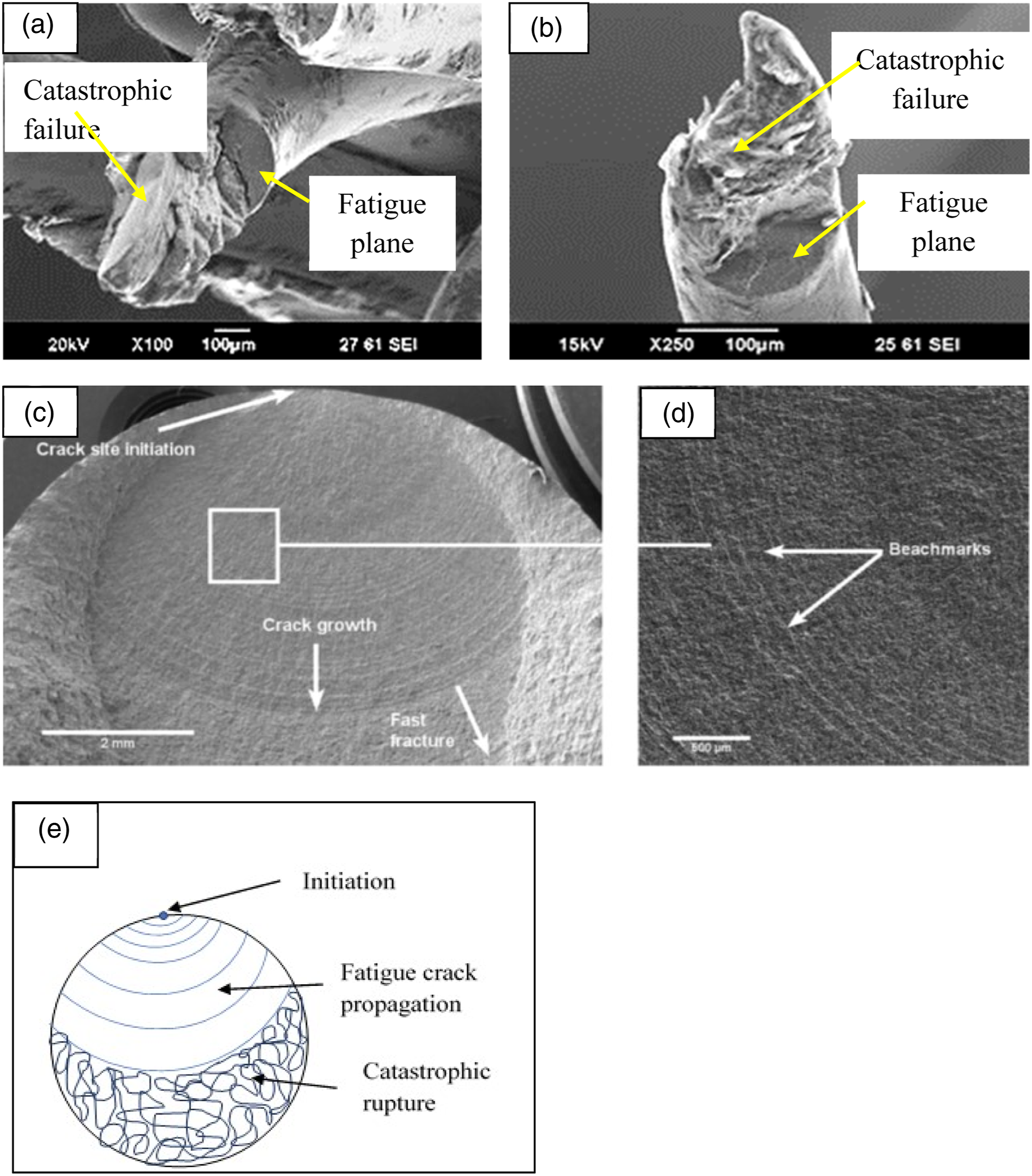
There are various factors which influence crack initiation and crack propagation. Some of these are inherent characteristics of the material and some of the factors are design related which can be suitably optimised to achieve the desired product life.
It is reported that steel with coarse grain microstructure shows poor fatigue life, whereas steel having fine grain microstructure shows better fatigue life. 42 Thus, metallurgical constituents and process conditions are optimised to obtain the desired microstructure for better fatigue performance.
For steel cord and bead wire, “fatigue” is very important since both are used in tyre which undergoes millions of cyclic stresses under extreme service conditions. Metallurgical constituents as well as patenting and drawing process are extremely important to create the desired microstructure to achieve ductility and fatigue performance. 43 Carbon content and purity of the wire rod are critical to produce different grades of steel cords viz normal tensile (NT), high tensile (HT), and super tensile (ST). Carbon content in NT grade of steel cord is 0.6%. Increase in carbon content is required to get enhanced pearlitic structure to achieve higher tensile strength. With 0.6% carbon content, perlite phase in the microstructure is around 75% which increased to 100% when carbon increases to 0.8%. Higher carbon percent also leads to grain refinement, resulting smaller grain size in the microstructure, which increases the tensile strength and hardness.44,45 In addition to microstructure, construction of the cord plays an important role for fatigue performance of steel cord. 45 Various factors which influence the “cord construction” includes filament diameter, number of filaments, lay length and type of cord (viz, open cord, compact cord, high impact cord etc.).
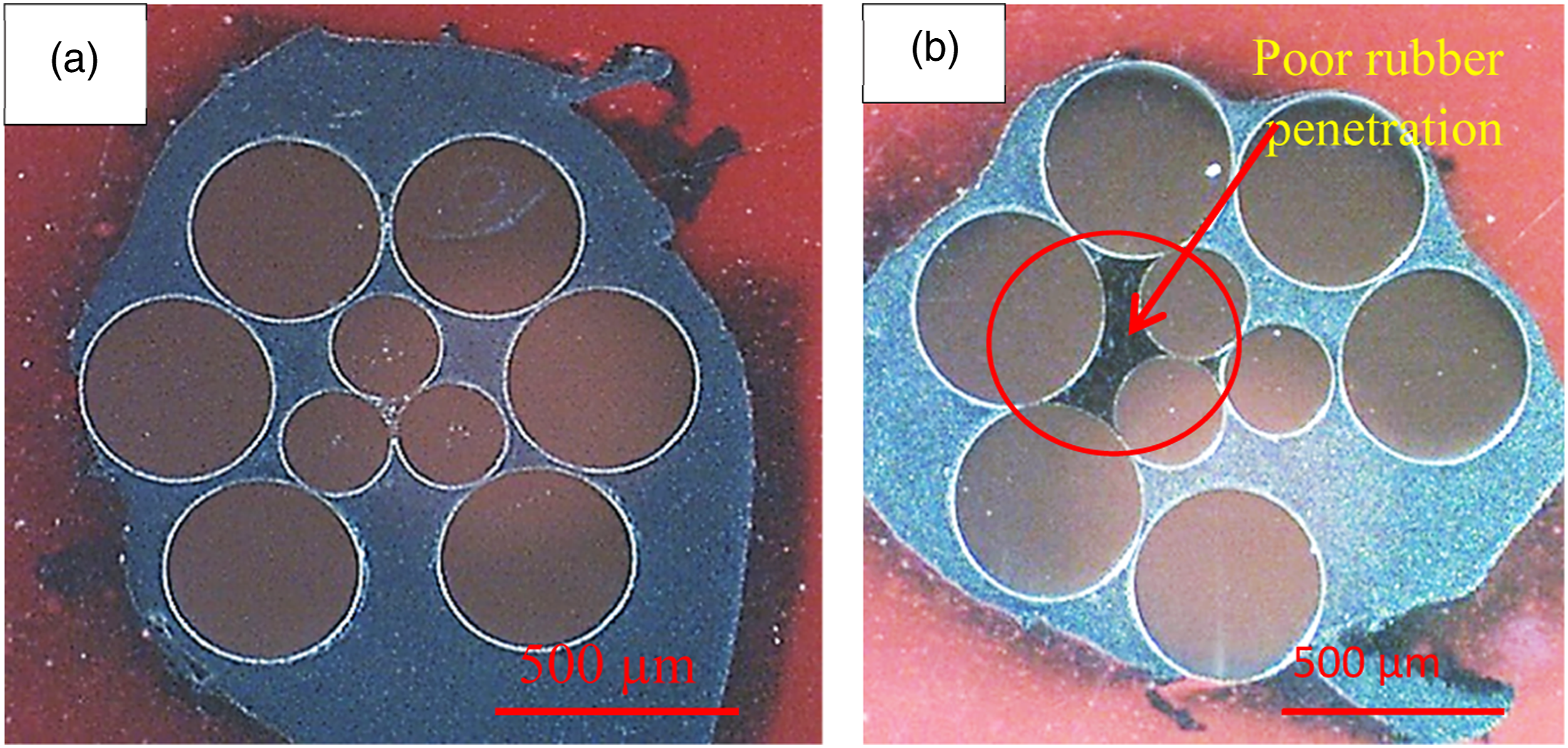
Various types of failure modes of service failed tyres described in Figure 3. Steel cord fracture due to fatigue can be easily distinguished from the nature of the fractured ends as already depicted in Figures 9(a) and (b). There are several factors which may influence the fatigue life of the steel cords inside the tyres. Metallurgical defects in steel cords, such as hard phases/inclusions, are susceptible to initiation of fatigue crack. Surface flaws and irregularities can act as notch and cause fatigue failure. Other factor, such as the level of rubber penetration inside cords also plays an important role for fatigue performance. Inadequate rubber penetration leads to fretting of the steel cords during service which leads to fatigue fracture.46–51 Fretting phenomenon occurs due to rubbing action between the filaments of steel cords, causing notch/defect on filament surface as illustrated in Figure 10 (steel cord extracted from serviced tyre). This becomes a weak point and may lead to fatigue fracture on prolonged service. Good rubber penetration reduces fretting phenomenon. Figure 11 depicts the level of rubber penetration in steel cord (shows good and poor rubber penetration). Severity of the service condition influences fatigue performance of tyre. For example, overloading and under inflation pressure of the tyre aggravates fatigue performance of tyres. A thorough knowledge and understanding on this helps to identify root causes of service failure of products like tyre. Steel cord extracted from tyre showing fretting on filament; (a) Longitudinal image; (b) Cross sectional image; (c) Cross section image without fretting. (a) Good rubber penetration; (b) Poor rubber penetration.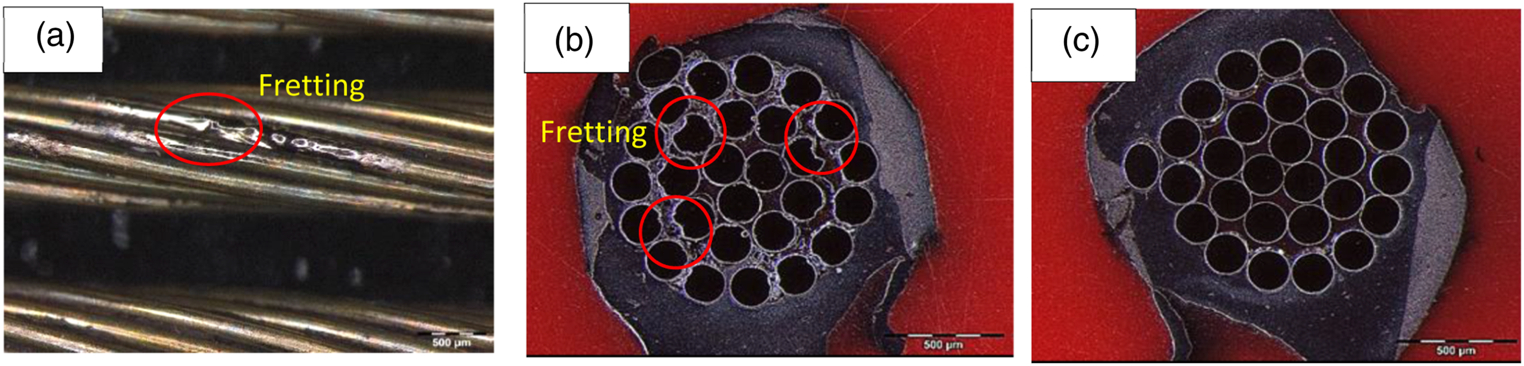
Shear fracture
Shear type of fracture can easily be identified from the nature of the fractured ends; which occurs at approx. 45° angle to the wire axis. Unlike ductile fracture, there is no plastic deformation prior to the ultimate fracture. Shear type of fractures occur primarily due to impact axial load (tensile) coupled with compression force perpendicular to the wire axis. Shear type of fracture may also occur in steel cord because of damage initiated by sharp object viz nail, stone etc. Hence, this type of fractures generally seen in service failed product like tyre. Since shear type of fractures are attributed to mostly impact or external injury, it is not linked with any defect or inherent issue of the metal wire unlike other types of fractures discussed in this article.
In service failed tyres, shear type of fracture observed often on the broken belt cords. Generally, it is found to be associated with either “concussion” type failure mode (refer Figure 3) or failure due to “through cut”. Concussion type of failure mostly happens because of high impact when the loaded vehicle encountered with road hazards like pothole, stones, blunt objects/edge etc. The impact force leads to sudden axial tension as well as compression force on the steel belt wires which results into shear type of fracture. Figure 12(a) portrays SEM image of the fractured cords, pertaining to a service failed tyres with concussion failure mode.
22
Many filaments of the broken cord found to be shear type of fracture. This finding corresponds with the hypothesis that sudden impact caused rupture of the belt cords which ultimately resulted in concussion failure of the tyre. Deeper analysis of the fractured filament surface through SEM reveals that its surface morphology is somewhat similar to that of ductile type of rupture that is “dimple morphology” as described in the preceding section (Figure 4). However, it looks like stretched or elongated; hence, it is termed as elongated dimple morphology
49
as described in Figure 12(b). (a) Typical shear type of fracture (steel cord filament) extracted from service failed tyre; (b) Elongated dimple morphology at shear fractured surface of bead wire.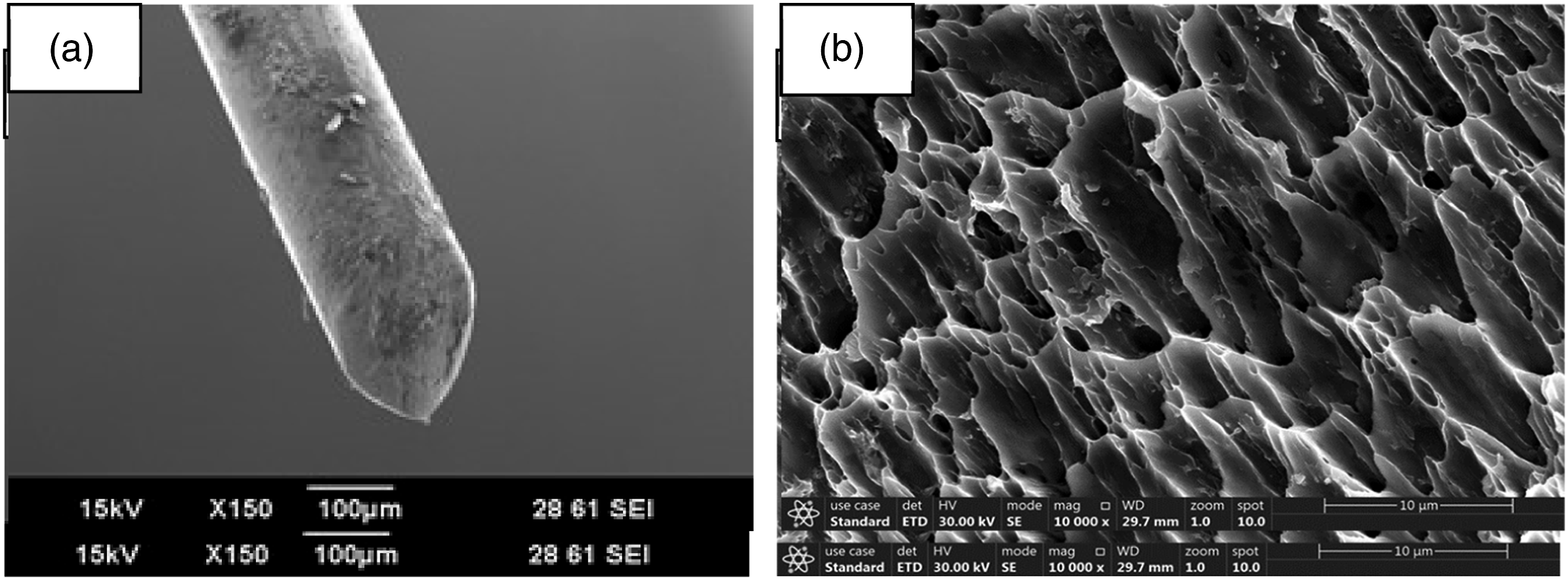
Torsion fracture
Torsion fracture is associated with torsional stress. A pure torsion fracture of steel cord/bead wire can be easily created in laboratory by twisting the wire in either clockwise or anti-clockwise direction till its failure. Fractured surface is perpendicular to the wire axis, having twist/rotation marks on the wire surface and final rupture marks known as “twist marks” is visible on the outer surface of the wire as well as on the cross section. Figure 13(a) is the image of the broken end of the bead wire after torsion test in laboratory. Figure 13(b) is the image of a steel cord filament pertaining to a service failed tyre, which indicates that the filament experienced some kind of torsional stress prior to the fracture.
52
(a) Broken end of a torsion tested bead wire (ductile torsion fracture); (b) Broken end of a torsion tested steel filament (ductile torsion fracture); (c) Torsion fracture in steel cord filament extracted from a service failed tyre (ductile torsion fracture); (d) Broken end of a torsion tested steel filament (brittle torsion fracture).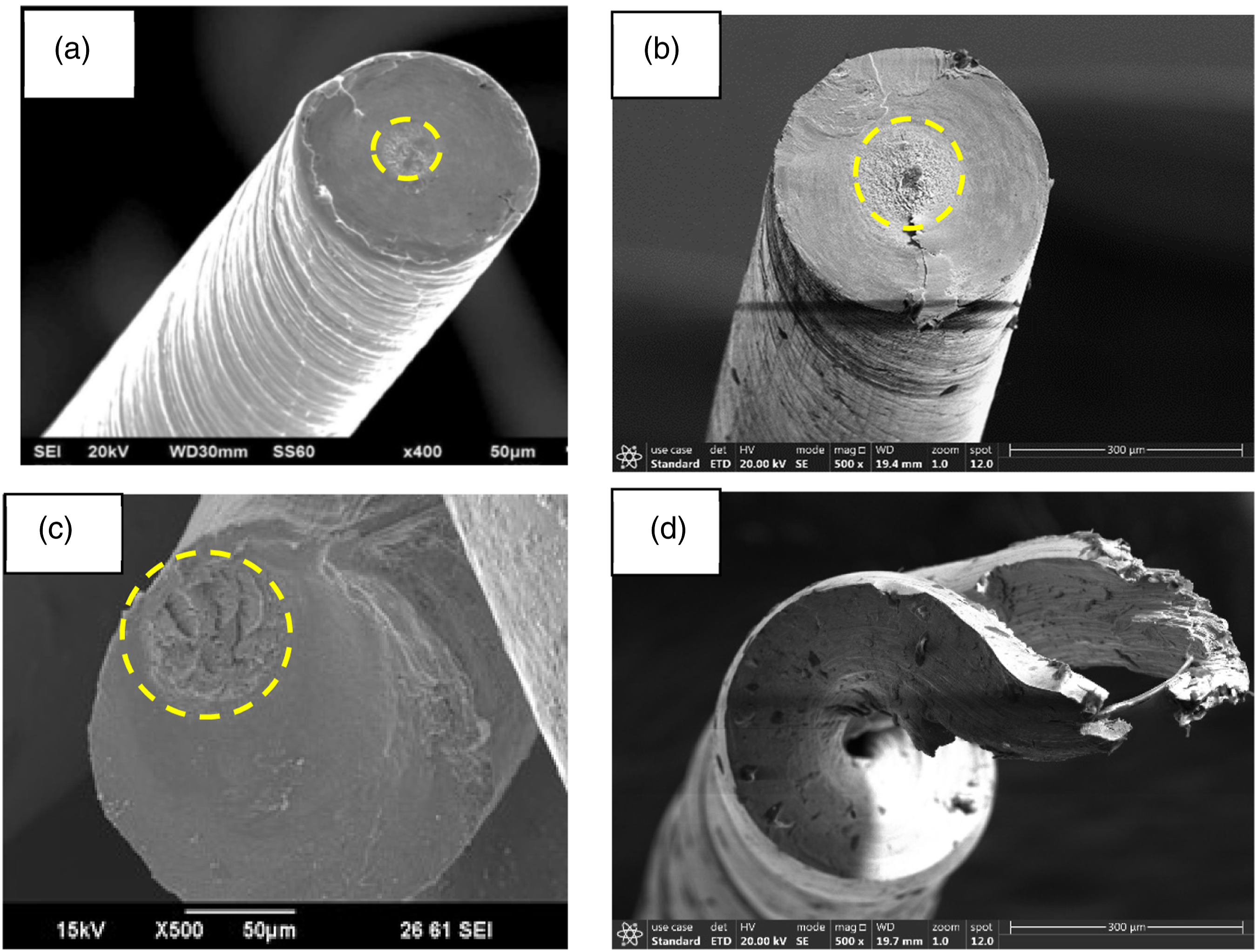
Torsion property of the wire is extremely important for manufacturing of bead wire and steel cord. Preparation of steel cord involves twisting/bunching of filaments at different stages. Hence, desired level of torsional ductility is essential for bead wire and steel cord. ‘Numbers of turns to break’ is the indicator of the torsion property; therefore, usually it is a quality control test parameter of bead wire and wire rod used for steel cord manufacturing. Torsion fracture may be either ductile type or brittle type.53–57 Figures 13(a) and (b), actually represents a typical “ductile torsion. If the wire doesn’t possess the desired level of ductility, the characteristic nature of the brittle torsion fractured surface looks different as depicted in Figure 13(d). 57
The mechanics of torsional crack/fracture and the factors which influence the torsional characteristic of metal wire were studied by several scientists.58–62 Key manufacturing process conditions which influence the torsional characteristics includes patenting and temperature control during drawing process.
Torsion type of fracture is rarely seen in product like tyres. However, it is occasionally found in steel cord filament of service failed tyres as depicted in Figure 13(c). Failure investigation of the serviced failed tyre indicates that partial fracture of the belt cord (few filaments) occurred due to some impact which lead to torsional stress on the remaining filaments prior to the ultimate failure.
Corrosion fracture
Corrosion is the degradation of metal caused by a chemical reaction between the metal and the environment. The rate of corrosion depends upon the type of metal and the environment in which it is exposed. Corrosion of steel in presence of moisture/water is quite common which is also known as rusting. The phenomenon of rusting of steel is a chemical reaction (ref Figure 14(a)), where iron (Fe) is oxidised to ferric oxide (Fe2O3), forming rust layers causing localized pitting. This leads to stress concentration in steel cord due to reduced effective cross-sectional area and hence, it became a weak point for initiation of crack.63–66 In case of steel -rubber composite product like tyre, corrosion of steel cord is one of the common causes for service failures. (a) Schematic diagram of corrosion mechanism of iron in contact with water and oxygen; (b) corrosion on the steel cord filament of service returned tyre; (c) and (d) Steel cords extracted from service failed tyres showing corrosion fractures, pitting on the surface and loss of material due to corrosion.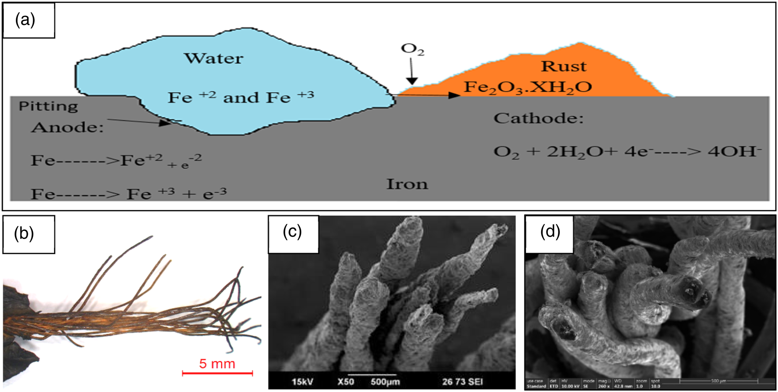
During the service life of the tyre, it encounters with tread cut, penetration of sharp object/nail. This facilitates water seepage through these cuts/holes resulting in corrosion of steel wire in the adjoining area. This becomes a vulnerable point for separation. Interfacial adhesion between steel cord and rubber gets adversely affected due to moisture and rusting. Moreover, this causes corrosion on the steel cords of belt and body ply of radial tyre which adversely affect wires strength. These pits/local corrosions drastically reduce the wires fatigue life.67–72 Due to loss of strength, steel cords became susceptible to break easily against any impact. 73 This makes the affected area further weak which ultimately may lead to concussion type of failure. Figure 14(b) depicts the optical image whereas, figure 14(c) and 14(d) depicts SEM images of the typical corrosion fractures of steel cords, extracted from a service failed TBR tyre. The root cause was found to be associated with nail penetration which ruptured few cords of different belt layers as well as body ply. However, it had not resulted immediate tyre failure. Corrosion on the steel cords at the affected area happened during subsequent running before the ultimate failure (concussion).
Therefore, in nutshell corrosion phenomenon of steel cord in tyre is common; however, the root causes are linked with cuts/penetrations. The ultimate failure mode is either separation or concussion.
Delamination fracture
In delamination type of fracture, a thin layer of material is separated/peeled off from the wire surface as depicted in Figure 15(a) and (b). This type of fracture may happen during production of wire rod (precursor material for making bead wire/steel wire) at any intermediate stage. The causes for the delamination type of fracture are predominately linked with few specific issues/defects in wire rod manufacturing viz. Mechanical damage/cut or edge crack at the wire surface, heavy over lapping and entrapment of residual oxide scale. (a) and (b) Showing the typical delamination of steel cord filament.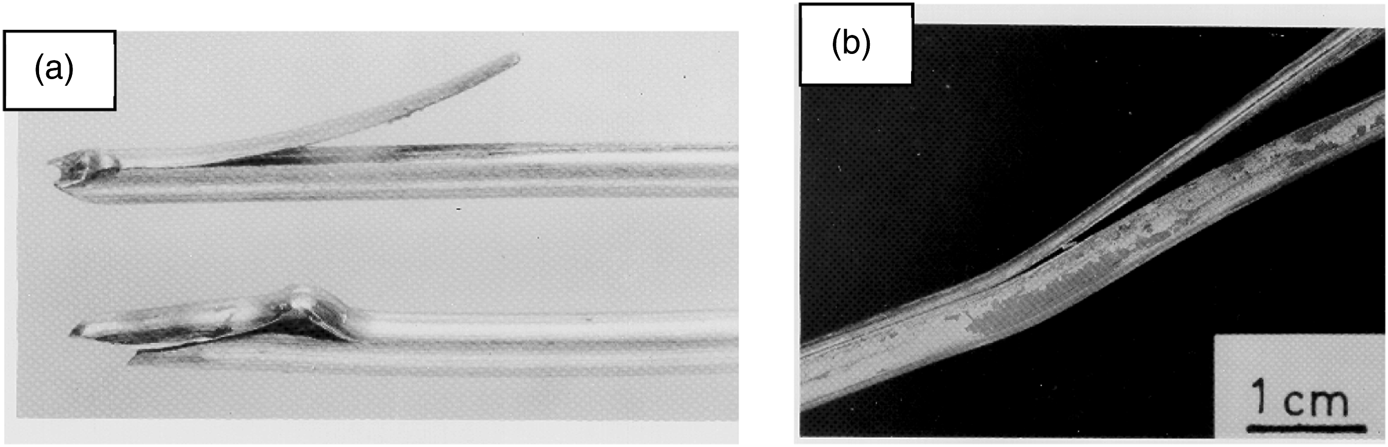
Mechanical damage/cut on the wire surface generally happens due to some defects on the guiding pulley used in production of wire rod from iron bar (billet) during hot rolling process or damaged dies, used in drawing process. Figure 16(a) depicts a kind of surface damage on wire which is extended to several times during subsequent drawing process which may lead to delamination. If it does not lead to breakage during wire rod manufacturing, then it remains as a defect and an area of potential failure at subsequent stages of manufacturing in a product during its service. Schematic diagram of various defects in wire rods which lead to delamination; (a) Severe mechanical damage; (b) overlap in wire rod; (c) residual oxide entrapment; (e) surface crack on the wire rod (cross section).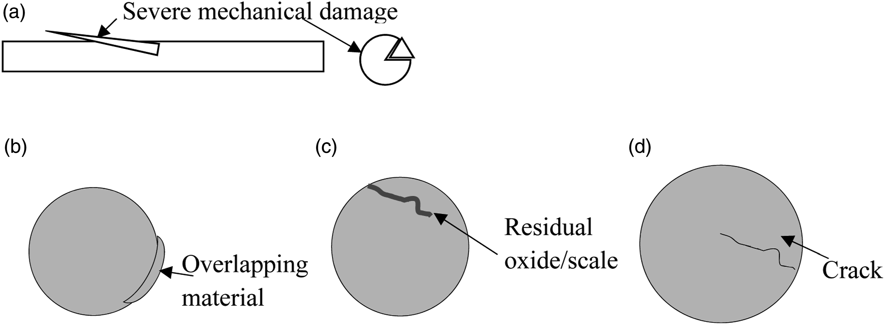
Localized “overlapping” happens sometimes at the hot rolling stage. The overlapping material behave like foreign material and may lead to delamination type of fracture at the manufacturing process of bead wire/steel wire. Figure 16(b) showing the schematic diagram of overlap in wire rod. Oxide layer is formed during casting of billets and hot rolling of wire rods. This oxide layers are removed either mechanically or chemically prior to subsequent drawing process. Entrapment of oxide scale within the wire rod happens sometime during hot rolling process. 74 This leads to crack and finally results into breakage during subsequent drawing stages. Figure 16(c) Shows the schematic diagram of residual oxide entrapment in wire rod. Longitudinal cracks on wire rods are one of the most common defects observed in the steel wire manufacturing. 75 Usage of such defective wire rods as input material for steel cord and bead wires manufacturing can lead to delamination. Figure 16(d) show the schematic diagram of crack on wire rod (cross section).
In summary, delamination type of fracture/failure generally happens during manufacturing of the wire. However, the causes (as mentioned above), if do not lead to fracture during manufacturing, the defect remains in the filament/steel cord, used for making rubber products viz tyres. In such cases, delaminated type of rupture may be seen in service failed products.
Weld fracture
Welding in steel cord is done to join two broken ends of the cord. Breakage may happen during manufacturing process of the steel cord; hence welding is essential to produce full length bobbin/spool. However, weld is a weak point and thus susceptible to fail (break) during service of the product like tyre.76–78 “Weld fracture” happens at the welding location and thus can be easily identified by the nature of the fractured surface which is elaborated in this section. Figure 17(a) depicts a typical weld in steel cord, dimension of which is specified and controlled (diameter of weld should not exceed more than 10% of steel cord maximum diameter). (a)Typical weld in steel cord; (b) Weld fracture of steel cord extracted from TBR service failed tyre; (c) microstructure of fully drawn filament (drawn perlite structure); (d)Microstructure of weld zone after annealing (tempered martensite).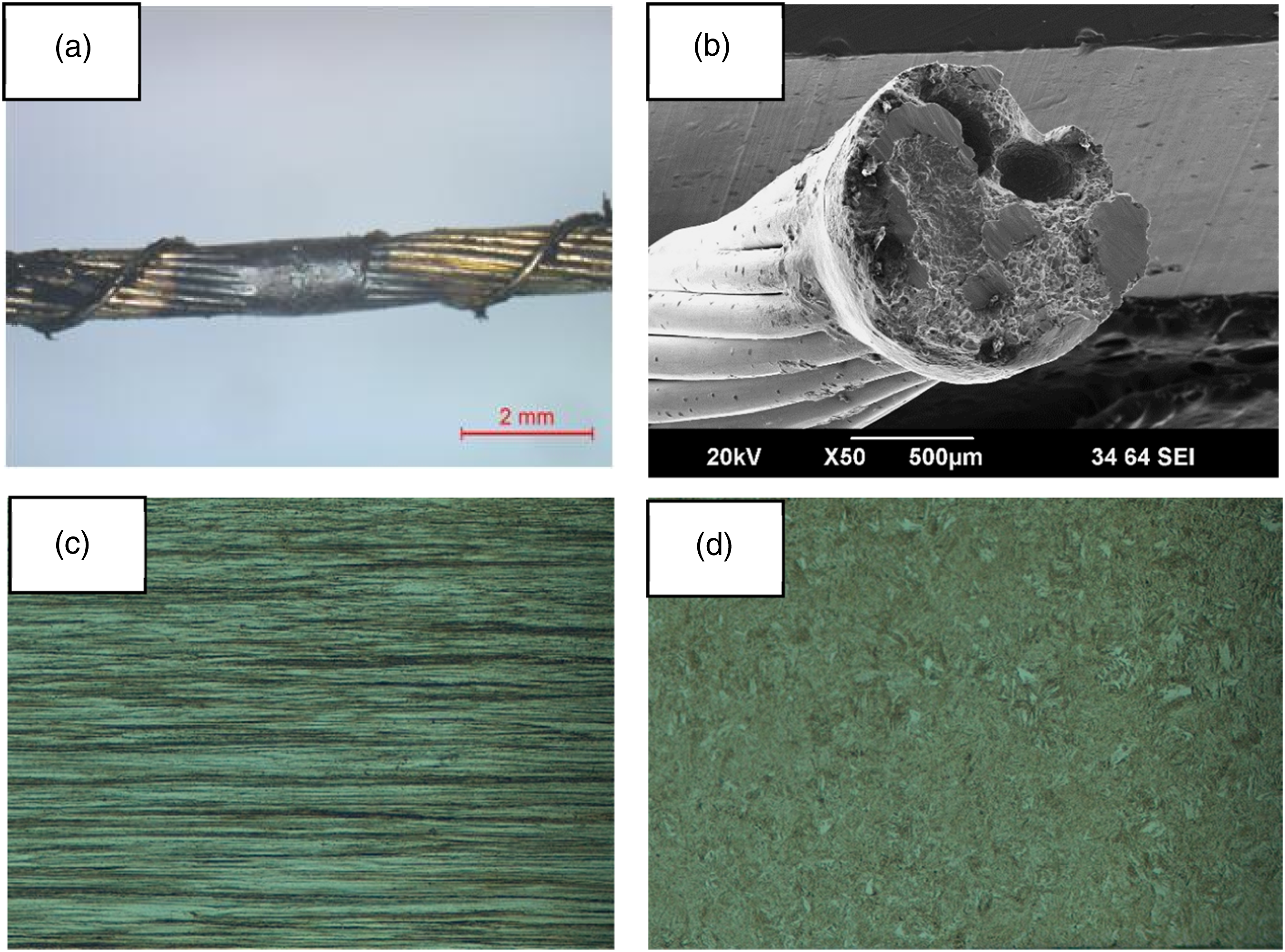
Typically weld strength is around 40%–50% of the original strength of the steel cord and hence susceptible to break under load during service of a tyre. In TBR tyre, steel cord constitutes two major components viz. Body ply (single layer) and belt (multiple layers) as described in Figure 1. Steel cord used in body ply are more sensitive to weld fracture during extreme service conditions. The probability of weld fracture increases if the weld is located at the sidewall region of the tyre which undergoes flexing to a higher degree during service. Weld fracture is very easy to recognise than any other type of fractures because fracture always happens at the weld location. 79 Figure 17(b) shows a typical weld fracture of steel cord (body ply) extracted from a service failed TBR tyre.
Microstructure of the weld region is different than that of the steel cord filament. Figure 17(c) depicts the microstructure of the fully drawn steel cord filament which is known as “drawn pearlite structure”. Figure 17(d) describes the microstructure of the weld region which is “tempered martensite structure”.80,81 It is hard and brittle in nature. In addition to this, weld region is prone to have porosities and oxides as described in Figures 18(a) and (b) respectively.82–84 (a) Overview of the welded sample after metallurgical sample preparation and etching; (b) Porosities in weld region; (c) Oxides (Iron oxide) at weld region.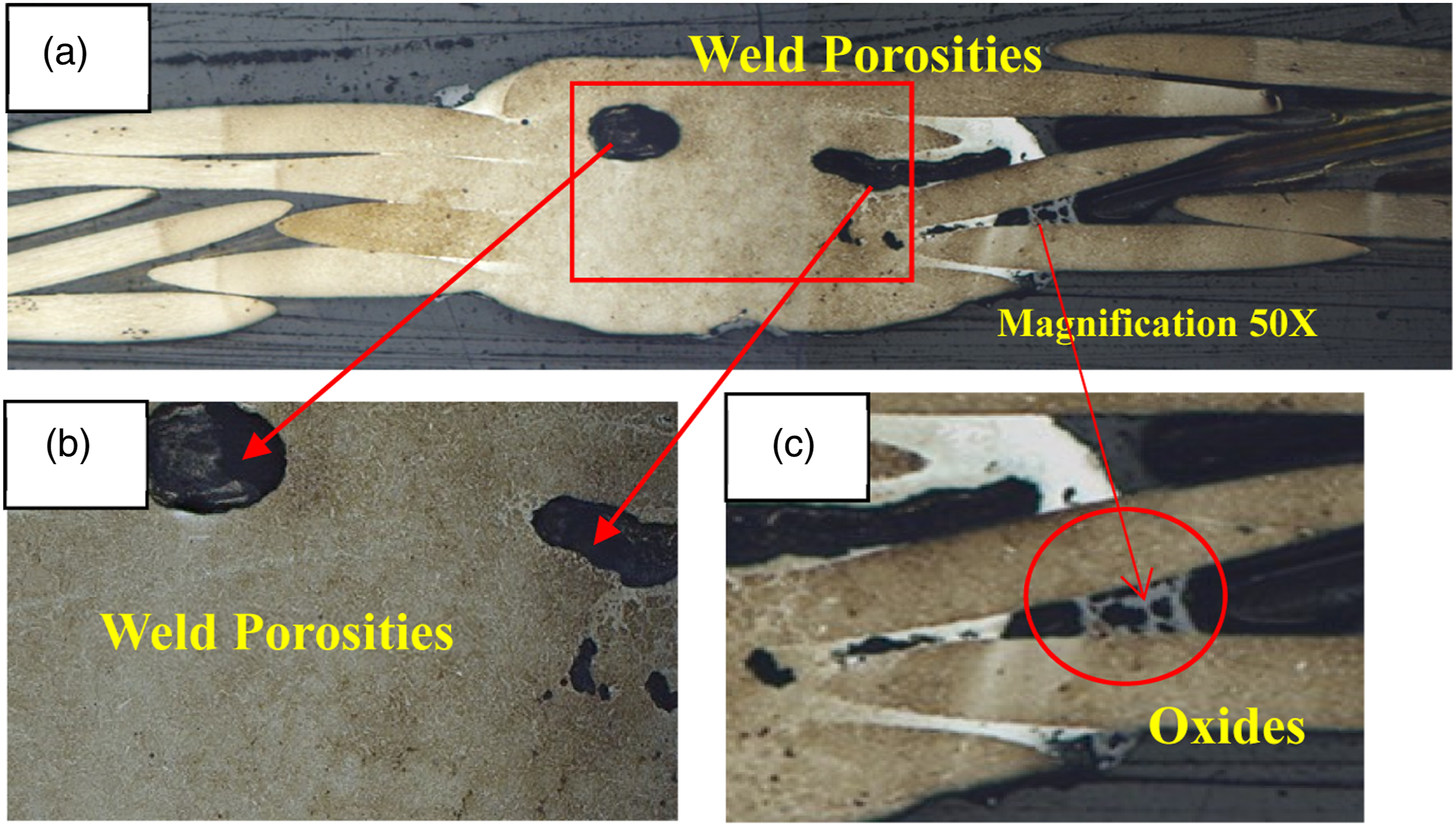
Summary and conclusion
In this article nine different fracture types of fractures have been discussed elaborately which are predominantly found in steel cords and bead wires during service or its manufacturing process. Unique characteristics of each type of fracture were discussed in this article. A thorough study of these features throws light on the probable root causes of such failures. For example, ductile fractures represent overloading, shear fractures represent impact force on tyre, fatigue fracture might indicate high stress concentration or material abnormality in steel cords, bead wires and so on.
Hence, fractography is crucial for failure analysis and tyre forensic investigation. Microscopic analysis simultaneously plays a significant role in the execution of fractography of various materials. SEM and OM have been used extensively for the detailed study of fractography of fractured surface of steel cords and bead wires.
Understanding on different types of fracture which occur in the steel cord and bead wires can be very useful for tyre forensic investigation. The contents of this review are likely to be of interest to specific industry domain viz. Manufactures of steel cord, bead wire, tyre and other rubber-steel composite products. Case studies on investigation on actual failures of steel or rubber -steel composite products will not only utilize the fundamentals described in this article but also enrich the knowledge and understanding further on this subject.
Footnotes
Acknowledgements
The authors would like to thank Hari Shankar Singhania Elastomer and Tyre Research Institute (HASETRI) for giving us permission to publish our research work. Authors would also like to acknowledge Mr Dilip Rathwa for his contribution on sample preparation and Ms Sushmitha H for her assistance in some part of literature review referenced in this article.
Declaration of conflicting interests
The author(s) declared no potential conflicts of interest with respect to the research, authorship, and/or publication of this article.
Funding
The author(s) received no financial support for the research, authorship, and/or publication of this article.