
Abstract
To investigate the confining effect and axial compressive behavior of rubberized concrete (RuC) confined by steel tube, axial compression tests were carried out on 12 circular RuC cylinders confined by steel tube. The cylinders considered parameters such as steel tube thicknesses (2 mm, 3 mm, 4 mm) and rubber volume replacement ratios of the fine aggregates (0%, 10%, 20%, and 30%). It was observed that the compressive strength of RuC decreases as the rubber volume replacement ratio increases. However, an increase in steel tube thickness enhances the confining effect of the core RuC, leading to an increase in its compressive strength and the corresponding strain, similar to that of conventional concrete. Moreover, post-peak curves are more likely to exhibit a strengthening part in confined concrete with more rubber content. Furthermore, a model was developed to determine the compressive strength of RuC confined by steel tube. Finally, an axial stress-strain model of steel tube confined RuC was proposed, which was validated against test results.
Keywords
Introduction
Over the past few years, the amount of waste rubber has significantly increased due to the extensive development of the automobile industry and rubber products, resulting in a serious burden on the ecological environment. According to the US Tire Manufacturers Association, approximately 4.5 million tons of used tires were produced in the United States in 2019, with a recycling ratio of 75.8%, as shown in Figure 1(a).
1
Similarly, in 2019, China’s auto industry produced around 3.50 million waste tires, resulting in a total of over 12.8 million tons, of which only 6.55 million tons were recycled, according to the China Renewable Resources Recovery Industry Development Report,
2
as shown in Figure 1(b). Based on the above data, it can be concluded that the reuse of waste tires is still limited, and current recycling methods such as heat recovery and landfill will cause secondary pollution to the environment, highlighting the need for the development of more eco-friendly recycling methods.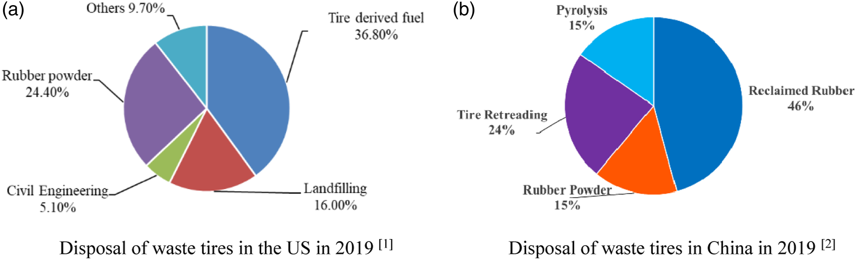
Rubberized concrete (RuC) is a promising application of waste tires that involves adding rubber aggregates to concrete in a certain proportion. The addition of rubber aggregate reduces the brittleness of concrete, improves its ductility, and reduces crack formation. 3 Compared with conventional cement-based concrete, RuC has superior performance in terms of elasticity, impact resistance, heat insulation, noise reduction, and durability.4,5 However, the partial replacement of fine or coarse aggregates with crumb rubber has been found to reduce the compressive strength and elastic modulus of RuC. 6 As a result, it has been suggested that RuC should be used for non-structural components, such as railway sleepers, or for low-strength demand components with a rubber aggregate volume replacement ratio of no more than 20%. 7 This limits the application of RuC in civil engineering and reduces the reuse ratio of waste tire rubber.
To address the limitations of RuC in engineering applications due to its low strength and elastic modulus, one approach is to apply confinement pressure to RuC using an external steel tube, which puts the core RuC in triaxial compression. 8 This composite member, called rubberized concrete-filled steel tube (RuCFST), exhibits improved compressive strength and ductility.9,10 Gholampour et al. conducted experiments on the axial compressive behavior of RuC under active confinement. 11 The tested RuC specimens had rubber replacement ratios ranging from 0% to 18% and a confinement level up to 0.67, defined by fl/fco, where fl is the lateral active compressive stress and fco is the cylinder compressive strength of concrete. The results showed that active confinement significantly increased the compressive strength and corresponding strain of RuC. As the rubber replacement ratio of RuC increased, its compressive strength decreased, but axial and lateral deformability improved. Abuzaid et al. conducted compression tests on short columns made of RuCFST. 12 The RuCFST columns had lower axial compressive capacity and higher ductility than ordinary CFST columns, indicating that RuCFST is suitable for members with high seismic performance demands. Similar conclusions were reached by Silva et al., 13 Duarte et al., 14 and Liu. 15 Although several studies have investigated the axial compressive behavior of RuCFST columns and RuC under active confinement, few have reported on the failure mechanism of RuC under high levels of confinement by a steel tube, especially with a confinement level exceeding 0.7.
To gain a comprehensive understanding of the compressive behavior of RuCFST columns, it is necessary to conduct further research on the mechanical properties and compressive stress-strain behavior of RuC when laterally confined by a steel tube. In order to achieve this goal, axial compression tests were performed on rubberized concrete specimens confined by a steel tube. The tests aimed to investigate the impact of rubber replacement ratio and steel tube thickness on the failure mode and compressive stress-strain behavior of the specimens, which ranged from 0.12 to 0.9 in confinement coefficient and 0%–30% in rubber replacement ratio.
Experimental program
Test materials
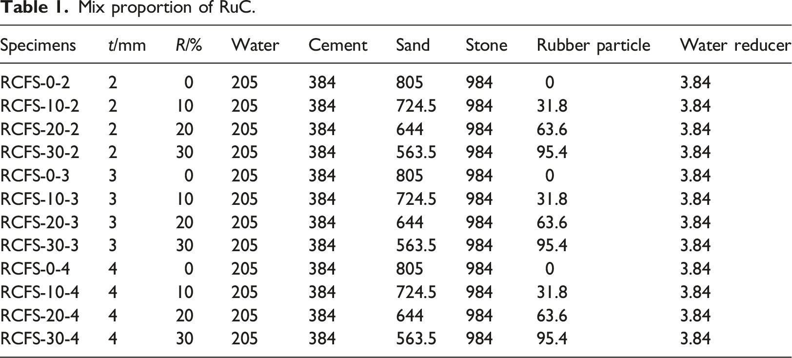
Mix proportion of RuC.
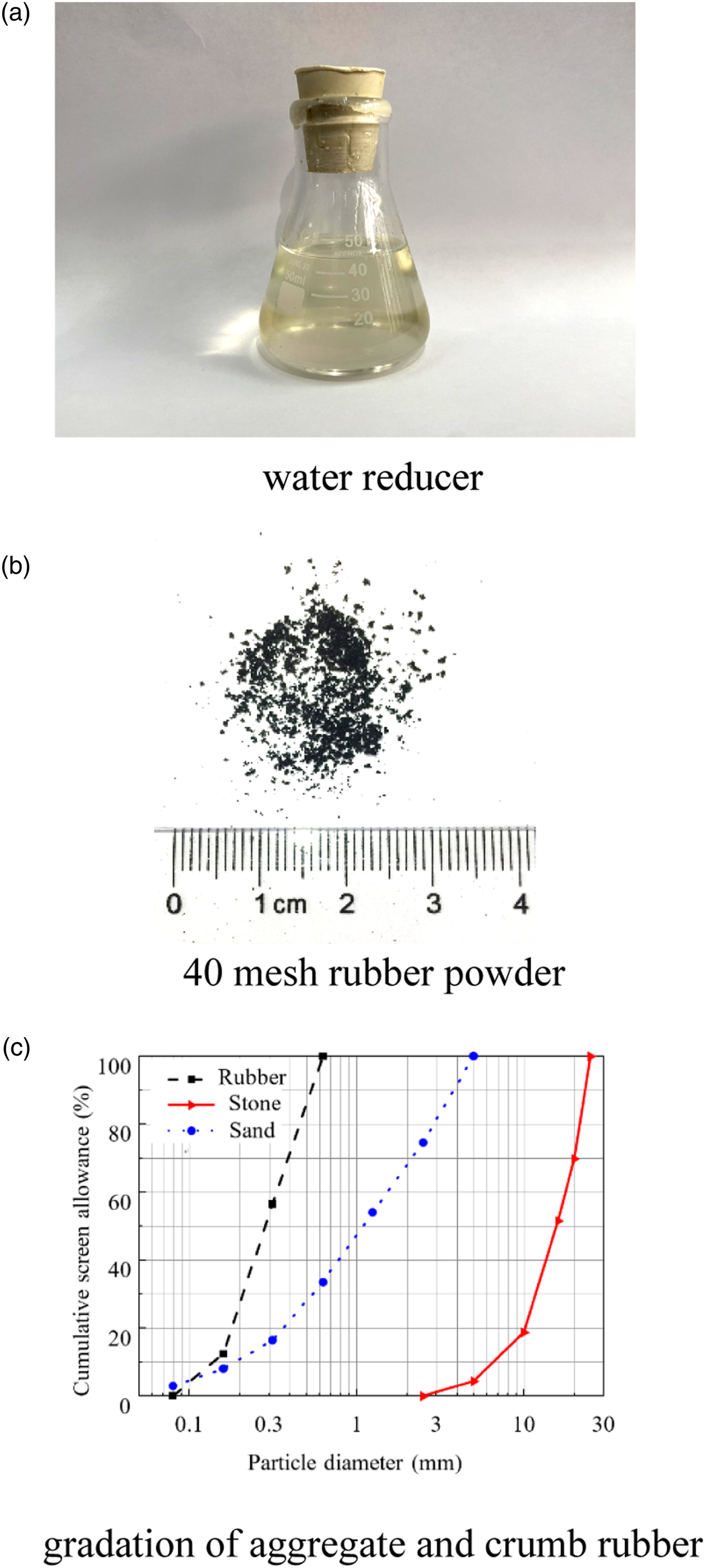
Experimental material. (a) Water reducer, (b) 40 mesh rubber powder, (c) gradation of aggregate and crumb rubber.
Specimen details
A total of 12 RuC cylinders confined by steel tube were prepared. The exterior steel tube of the specimens is 165 mm in diameter and 330 mm in height, with different wall thicknesses t of 2 mm, 3 mm and 4 mm, respectively. The tensile test results of the steel tube material are shown in Figure 3. The steel tube has a yield strength of 242 MPa. Four different rubber volume replacement ratios R of 0%, 10%, 20%, and 30% were considered in RuC. The specimens were labeled by the rubber replacement ratio and the steel tube thickness. As shown in Table 1, RCFS-20-3 presents that the steel tube confined rubberized concrete specimen is 20% in rubber replacement ratio and 3 mm in the thickness of the steel tube. The stress-strain curve of the steel tensile test.
Specimen preparation
Tested RuC specimens were prepared according to the mix proportions described above. To reduce the friction between the core RuC and the interior wall of the steel tube, a layer of grease was applied to the interior wall of the steel tube before the preparation of RuC cylinders. The raw materials were mixed for 3–5 min, and then the mixtures were placed into the steel tube and vibrated. Finally, the top surface of the mixture was smoothed and then naturally cured. Meanwhile, RuC cubes with a size of 100 × 100 × 100 mm were proportioned for all mixes to obtain the unconfined compressive strength of RuC.
Test procedure
The loading diagram and measuring arrangement were illustrated in Figure 4. A circular steel plate with a diameter slightly less than the inner diameter of the steel tube was placed on the core concrete during loading, to apply the axial load directly to the core concrete. Three axial and three circumferential strain gages installed at the mid-height of each specimen were used to measure the axial and circumferential strains of the steel tube. A displacement meter was placed between the steel loading and supporting plate to measure the axial deformation of the core RuC. Arrangement of strain gauges and loading set-up.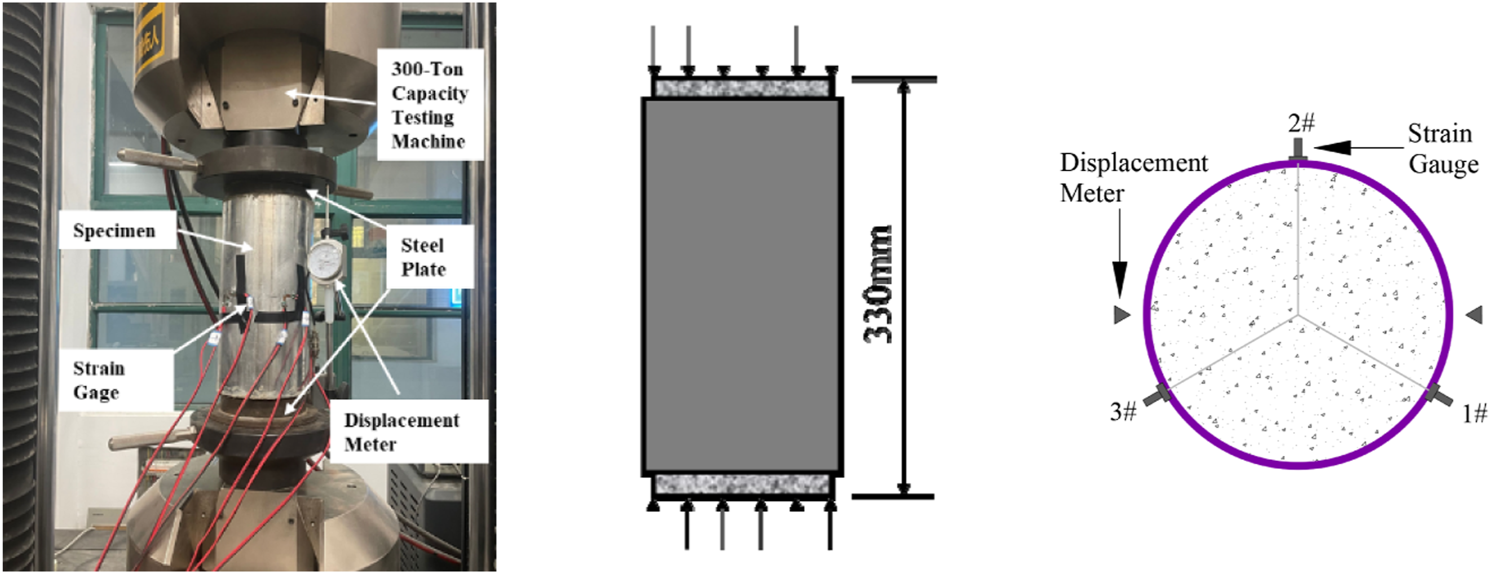
A loading machine with a 3000 kN capacity was utilized to perform the axial compression tests. The loading speed was 0.1 mm/min. Each specimen was first preloaded to 0.15Ppre and then unloaded, where Ppre is the predicted ultimate load of the specimen. Afterward, the specimen was loaded under monotonic compression until its axial deformation reached a limit of 40 mm. Meanwhile, rubberized concrete cubes were tested for 28 d compressive strength following Chinese Standard for test methods of concrete physical and mechanical properties (GB 50081-2019). 16
Test results and analysis
Ultimate resistances
Test data.
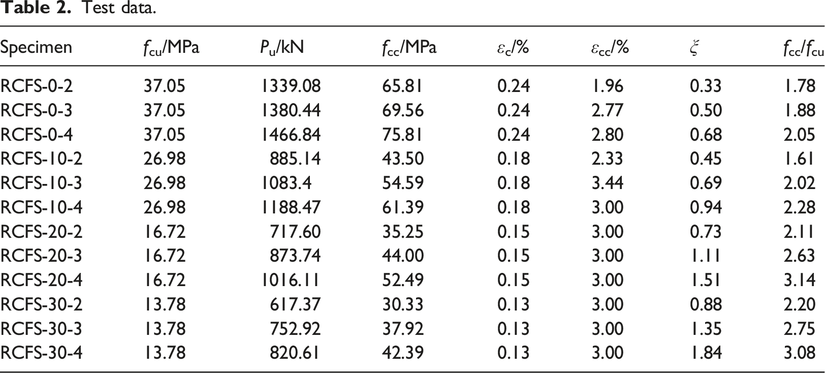
As can be found in Table 2, as the rubber volume replacement ratio R increases, the compressive strength of RuC decreases. For example, compared with that of ordinary concrete, the uniaxial compressive strength fcu of unconfined RuC with rubber volume replacement ratio R of 10%, 20% and 30% decreased by 27.2%, 54.9% and 62.8% respectively. This outcome can be attributed to the relatively lower strength and stiffness of rubber particles in comparison to natural aggregates. 7 However, being laterally confined by steel tube with a thickness of 3 mm, the peak compressive stress of confined RuC decreases by 21.52%, 36.74% and 45.49%, indicating that effective confinement by the steel tube improves the compressive strength degradation of RuC with higher rubber content. Moreover, the fcc/fcu value of confined RuC is generally higher than that of confined ordinary concrete, which also testifies that the improvement of the axial compressive capacity of RuC confined by steel tube was more significant than that of ordinary concrete.
For specimens with the same rubber volume replacement ratio, for example, when R = 20% and the steel tube thickness t is 2 mm, 3 mm and 4 mm, respectively, the ultimate load Pu decreases by 46.44%, 36.74% and 30.76% compared with that of confined ordinary concrete, respectively. And fcc/fcu increases with thicker steel tube for specimens with the same rubber volume replacement ratio R. It can be obtained that thicker steel tube provides more effective confinement and consequently leads to a more improved compressive strength of confined RuC.
P-ε relation curve
The P-ε curves of the specimens with different rubber replacement ratio R and steel tube thickness t were presented in Figure 5. It can be observed that the post-peak curves of steel tube confined RuC cylinders are relatively flatter compared with that of steel tube confined ordinary concrete, indicating better ductility of confined RuC. When the rubber aggregate replacement ratio R reaches 20%, the post-peak curve of the specimens shows no obvious descending trend and even begins to exhibit a strengthening trend. When the replacement ratio R increases, the initial stiffness of the specimens decreases because of the elastic modulus degradation of RuC. The reason for this phenomenon is that, under the same steel tube wall thickness, as the rubber replacement rate increases, the confinement coefficient of the steel tube on the core concrete increases, which in turn increases the strength variation rate.
12
The relationship curve of load versus axial strain under different replacement ratios. a) t = 2 mm, (b) t = 3 mm, (c) t = 4 mm.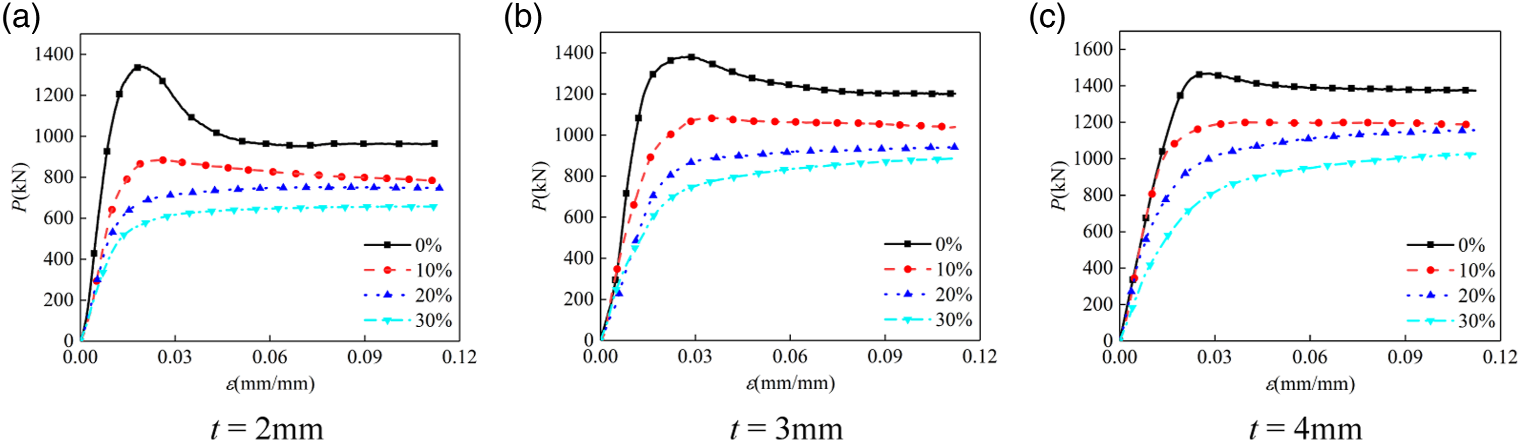
As also can be found in Figure 5, increasing the thickness of the steel tube also tends to flatten the post-peak curve of RuC, indicating an enhancement of the effective confinement. The confinement produced by the exterior steel tube prevents the development of the internal crack of the core RuC, and improves its post-peak behavior under compression. When the load increased, the transverse deformation of the core RuC further developed and led to a continuous increase in confinement stress by the steel tube, which further limits crack development. Therefore, the core RuC under confinement shows a hardening post-peak behavior instead of a softening one.
Peak stress of rubberized concrete confined by steel tube
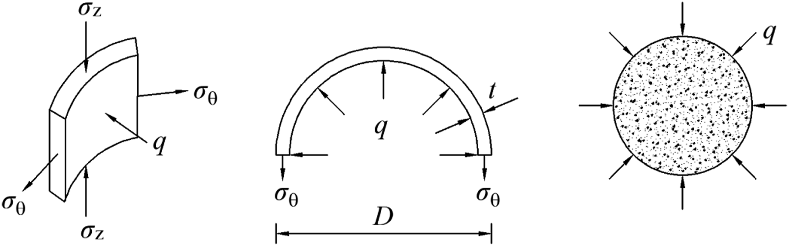
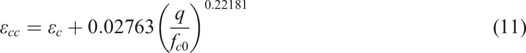
Figure 6 shows the stress diagram of the core concrete and the exterior steel tube. The core concrete expands laterally under axial compression and generates the circumferential stress of the exterior steel tube, resulting in the triaxial compression of the core concrete. As the recorded strain shows, the steel tube has yielded before the peak load. According to the measured circumferential and axial strain of the outer wall of the steel tube, the circumferential confining pressure q on the core concrete can be calculated by equation (1). Force and stress diagram of the steel tube and concrete.
The peak stress of triaxial compression strength of concrete fcc was calculated by an empirical formula as equation (2).
19


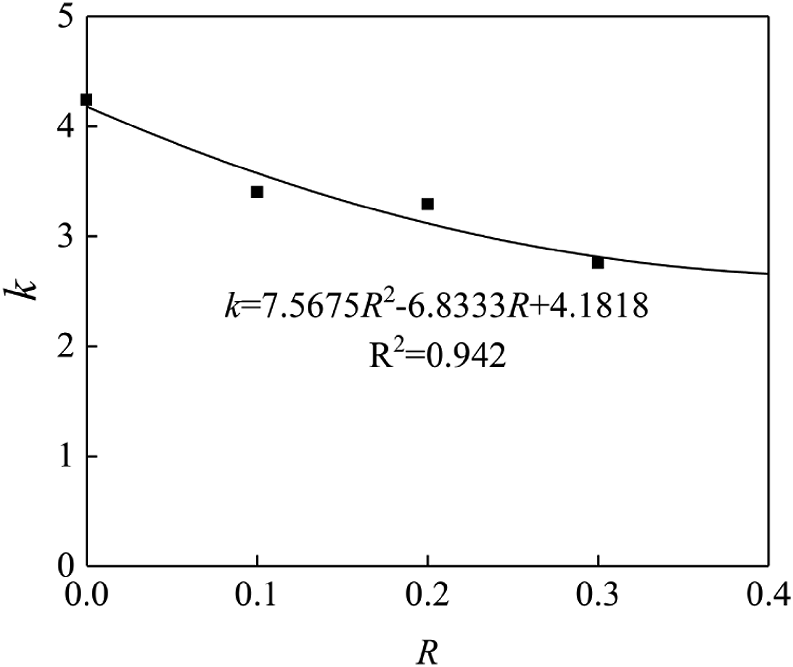
Richart et al. suggested a value of 4.1 for coefficient k of ordinary concrete under triaxial compression, which agrees well with the above equation (3). 19 As can be found from equations (3)–(6), coefficient k of RuC under triaxial compression is smaller than that of ordinary concrete. Though the relative strength enhancement fcc/fcu of confined RuC is generally higher than that of confined ordinary concrete, a smaller value of k indicates a smaller absolute strength enhancement of confined RuC because of the severe strength degradation of RuC with higher rubber content. This also indicates that the lateral confinement effect of steel tubes can offset some of the strength loss caused by the replacement of fine aggregate with rubber power, making it applicable to structural members subject to higher loads.
Figure 7 shows the relationship between the rubber volume replacement ratio R and coefficient k. The empirical formula of the compressive strength fcc of confined RuC was obtained through the analysis of the least square method K- R diagram.
Compressive constitutive model of RuC confined by steel tube
Several constitutive models of confined concrete have been studied experimentally. Lim and ozbakkaloglu proposed a general constitutive model for ordinary concrete and lightweight aggregate concrete cylinders under triaxial compression.
20
Fitted by relevant empirical formulas, Lim-Ozbakkaloglu model was determined by multiple key points, in which a softening inflection strain εc,i and a residual stress fc,res were introduced. Lim-Ozbakkaloglu model was found to predict the softening of concrete better than other models. Han et al. found that the constitutive curve of the core concrete in CFST is closely related to the confinement coefficient ξ.
21
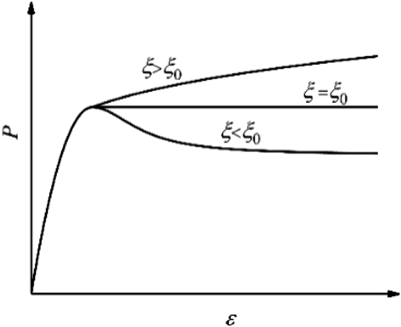
Han model is in a form of a parabola before the peak stress, and its post-peak curve is determined based on the value of ξ and a critical coefficient of confinement coefficient ξ0. When the confinement coefficient ξ<ξ0, the post-peak behavior of concrete is represented by a softening part. And the smaller ξ is, the faster the post-peak curve drops, and the earlier the softening appears. When ξ≈ξ0, the post-peak behavior is a platform. When ξ>ξ0, the post-peak curve shows a strengthening trend. And the larger ξ is, the larger the strengthening amplitude is, as shown in insert Figure 8. According to the test results, the critical value of confinement coefficient ξ0 = 1.10 when the Rubber Content R = 0%; ξ0 = 1.15 when R = 10%; ξ0 = 1.20 when R = 20%; ξ0 = 1.31 when R = 30%. The relationship between the coefficient ξ0 and the rubber content R was determined by a regression analysis Typical load-strain curve.
Based on the above analysis, the following compressive stress-strain model of RuC confined by steel tube was established based on Lim-Ozbakkaloglu model and Han model
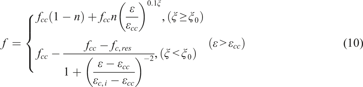

The inflexion strain εc,i and the residual stress fc,res is calculated as f-ε relation curve of each component.

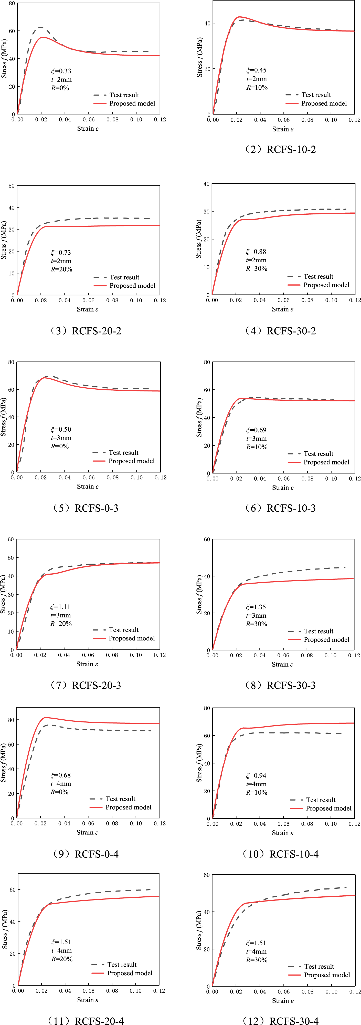
Conclusion
To investigate the confining effect and axial compressive behavior of RuC confined by steel tube, axial compression tests were carried out on 12 circular RuC cylinders confined by steel tube, the main conclusions are as follows: (1) Compared to the increase in compressive strength of ordinary concrete under lateral pressure of circular steel tube, at the same thickness of steel tube, the strength of the RuC with confinement by steel tube increased more significantly with an increase in rubber replacement ratio. This also indicates that the lateral constraint effect of the steel tube can offset a portion of the strength loss caused by rubber substitution for fine aggregates in concrete, making it suitable for structural members subject to higher loads. (2) Compared to ordinary concrete, rubber aggregate concrete exhibits a post-peak strengthening in the load-displacement curve under lateral confinement by steel tubes. Therefore, based on theoretical analysis and experimental results, this study establishes a calculation formula for the compressive strength and critical confinement coefficient ξ0 of concrete confined by steel tubes. (3) An empirical constitutive model for rubberized concrete confined by a circular steel tube was proposed in this paper. The model showed a high level of accuracy, especially for the cases where post-peak strengthening was observed.
Footnotes
Declaration of conflicting interests
The author(s) declared no potential conflicts of interest with respect to the research, authorship, and/or publication of this article.
Funding
The author(s) disclosed receipt of the following financial support for the research, authorship, and/or publication of this article: This work was supported by the Open Foundation of Shandong Key Laboratory of Civil Engineering Disaster Prevention and Mitigation (Shandong University of Science and Technology) (Grant No. CDPM2021KF05).