
Abstract
Specifications concerning road lighting and photometry of road surfaces were established more than 50 years ago. Road lighting design and road marking visibility were developed for vehicle driving. The observation distance defined by standards corresponds to interurban applications; however, within Europe these areas do not tend to be lit. The objective of the SURFACE project is to propose new geometries for the photometric characterisation of pavements, both adapted to different urban travel modes and new lighting technologies. This article reviews the available guidelines, standards, measuring devices and literature regarding geometries and road lighting applications, and presents the project SURFACE analysis and proposal. The SURFACE consortium recommends adding several new angles for different driving conditions and road users; 2.29° for urban environments and consistency with road marking standard, and 1° for extra-urban environment and consistency with previous geometries. A 5° angle, corresponding to 17-m viewing distance, could be an interesting compromise, suitable for urban driving at low speed, cycling and for scooters. The angles of 10° and 20° are under consideration for describing the boundary between diffuse and specular behaviour.
1. Introduction
Specifications concerning road lighting and photometry of road surfaces were established in the 1970s. 1 Road lighting design and road marking visibility were developed primarily for drivers of motorised vehicles. The observation distances defined by standards correspond to interurban applications; however, these areas are rarely lit in Europe.
Road luminance is defined in the EN 13201-series of European standards2–5 as the key parameter which road lighting has to fulfil in order to provide lighting intended to ensure the safety of road users after dark. Road surface luminances, which allow the perception of possible obstacles and of the environment, are based on a vision model 6 and then realised through artificial road lighting.
The design of a road lighting system includes determination of the optimal combination of lamp power, height, spacing and luminaire optics to provide the desired road surface luminance. A road class is assigned according to road and traffic characteristics, following national requirements based on CEN/TR 13201-1:2014. 7
Road surface luminance is the light quantity perceived by drivers. It is directly related to the luminous intensity emitted by a luminaire in a given direction and the reflective characteristics of the road surface in the same direction, towards the viewing direction of the observer. The intensity emitted by a luminaire is derived from the spatial luminous intensity distribution of the luminaire, usually measured in accredited laboratories equipped with a goniophotometer and provided by luminaire producers. The amount of light reflected from the road depends on the direction of observation and angles of incidence (or, geometries), and is represented by the luminance coefficient (q) of the road surface.
The luminance coefficient describes the geometric reflective behaviour of any material and in addition to road lighting design has applications including the creation of photo-realistic images, energy and lighting calculations. Since the lighting design can be done either before or after the road construction, road lighting calculations are usually performed using tabulated values of q for different road pavements, defined as reference pavements. EN standards also require on-site verification for compliance with national road lighting requirements. In this case, knowledge of the road pavement luminance values used in the design and the actual installed luminaire data are necessary. However, in practice the photometric characteristics of the pavements are not generally measured.8–11
This article presents results and recommendations of the SURFACE project. 12 The objectives of this project are to review existing measuring devices and to propose new geometries for the photometric characterisation of pavements, adapted to both different urban travel modes and new lighting technologies. The first part of this article presents quantities and basics which defines pavement photometry, according to existing guidelines and standards. Following a description of the SURFACE project, the second part of the article is a review of the laboratory and portable measuring devices used for road photometry, highlighting certain instrument characteristics. The third part focuses on available literature regarding geometries and road lighting applications and presents the analyses and recommendations resulting from the SURFACE project.
2. Pavement photometry
The method for photometrically characterising pavements was developed in the 1970s 1 and updated in 1982 13 and 2001. 14 The quantities used in road lighting characterisation are described in three reports from the International Commission on Illumination (CIE).15–17
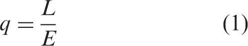
The surface of a pavement is classified according to its reflection properties. The most characteristic parameter is the luminance coefficient q, which is the ratio between the luminance L in cd/m2, which the observer sees, and the illuminance E in lux which is incident on the surface (equation 1).
Since the 1980s, for practical reasons the luminance coefficient was replaced by the reduced luminance coefficient r in cd/m2/lux, which is derived from q (equation 2).

A reduced coefficient table called r-table was defined, where the luminance coefficient r is given for a combination of fixed lighting angles β and tan ɛ (see Figure 1). The standardised viewing height is 1.5 m and the angle of observation α is constant at 1°, corresponding to an observation distance of 86 m. Lighting standards target an area of the road between 60 m and 160 m ahead of the driver, this being considered an important area for the detection of obstacles. It was also defined for interurban driving where the speed is about 80 to 90 km/h.
The photometric characteristics of the road surface depend on the angles of observation α, deviation β and incidence ɛ. By convention, according to CIE 066 and CIE 144, guidelines and road lighting standards, for the characterisation of road photometry α is set at 1°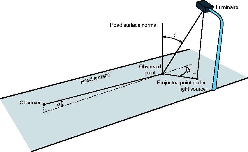
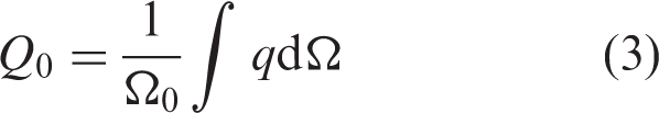
The average luminance coefficient Q0 represents the degree of lightness of the measured surface.
14
It is computed as the average of the luminance coefficients over the specified solid angle, Ω0 (equation 3).
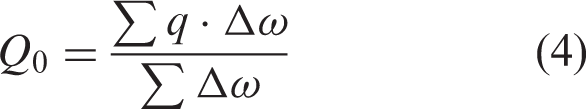
In practice, due to the finite number of measurements, the integration results in a numerical summation approximated with weighting factors corresponding to the solid angle attributed to each value Δω and given for each combination of tan ɛ and β angles (equation 4)
15
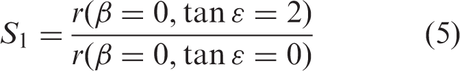
The specular factor S1 represents the degree of specularity (shininess) of the observed surface. It is defined as the ratio between the reduced luminance coefficients of two specific illumination conditions (equation 5)
Standard reflection tables are used worldwide, and they are based on measurements carried out in northern Europe in the 1960s and 1970s. 15 However, discrepancies have been found in more recent measurements.8–11 These discrepancies are attributed to the change in pavement surface technology and aging of the road surfaces.
3. The current limitations of road photometry
In EN 13201-3, 3 the geometries (lighting and viewing angles) at which the q values should be known is given and so is the format of the r-table (Table 3 of that standard). However, no values are given in the standard. The only published reference data were published in a CIE Technical Report, 15 which is more than 40 years old and which does not include information on measurement uncertainty.
In the past 40 years, pavements have changed, driver visual conditions have changed, and traffic behaviour has changed. As a consequence, current road lighting systems are designed using data of road pavement characteristics which may not be representative of actual road surfaces.8–11 Road surfaces and luminaires have evolved over time. Awareness of the importance of measurement uncertainty and its relationship with industrial tolerances has also increased. Some studies show that the currently available CIE data 14 may lead to errors on average luminance often over 30% and sometimes over 50%.11,18
The EMPIR (European Metrology Programme for Innovation and Research) research project SURFACE ‘Pavement surface characterisation for smart and efficient road lighting’ aims to overcome the current shortcomings of road surface photometry. 19 The goal of SURFACE is to provide necessary data and research to CIE, CEN and the road lighting community. This is achieved by evaluating the current state of the art of measurement devices and methods and by analysing the needs of road user safety related to visual conditions and pavement reflectance. The objective is to provide CIE and CEN with new reference data for current road surfaces and new reference geometries for luminance factor measurement. The new data and geometries should better correspond with the needs of road users, help with the development of smart and LED lighting and lead to a reduction of the environmental impact (including both energy consumption and light pollution) of road lighting installations.
4. Review of measurement methods and devices
A review of existing devices was conducted in order to evaluate the current state of the art of road surface photometry. The devices can be divided into two main subsets:
laboratory instruments, which are used to make absolute measurements and serve as a reference. portable devices, which are used to measure the road surface in-situ and provide a relative measurement.
4.1 Laboratory instruments
Laboratory instruments consist of a light source, a sample holder and a detector to measure the luminance. The geometry is usually designed to cover the different illumination angles defined in the r-table. Some parts are fixed, and some are mobile, depending on the chosen implementation. As the direction of observation is fixed in relation to the sample, the sample and the detector can be in a fixed configuration or move in conjunction with each other. Most of them are fully automated, which makes it easier to measure all the illumination positions. The detection needs to take into account the
An overview of European Laboratory instruments found in the literature
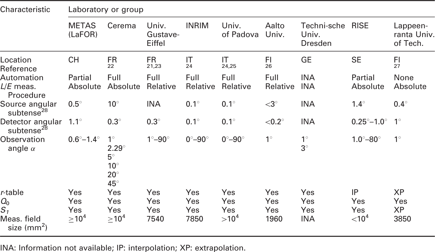
INA: Information not available; IP: interpolation; XP: extrapolation.
Laboratory setups are typically characterised by a large distance between the source and the sample (1 to 5 m), which results in good collimation angles (below 1° for most instruments), limiting the uncertainty on the illumination angle. The detector is often placed at a distance such that the acceptance angle of the detection is small.
They usually allow the measurement of the full r-table, at the cost of longer measurement times (from 30 minutes to several hours). For most of them, it is therefore possible to compute Q0 directly using the weighting factor given in CIE 066:1984, 15 which corresponds to the numerical integration over the considered solid angle.
These devices are expected to have relatively small measurement uncertainty, typically evaluated to be around 10%.23,29,30 They are therefore used to make the reference measurements necessary to calibrate the portable devices. However, a uniform approach is currently lacking regarding the calibration methodology, the measurement procedure, the traceability, and the measurement uncertainty of these instruments. These shortcomings will be addressed by the SURFACE project in subsequent work.
The main disadvantage of laboratory instruments is that they require samples to be extracted from the road, which is destructive and costly. For this reason, laboratory systems are not suitable to follow the evolution of road surface reflectance over time, and do not allow multiple measurements in the exact same spot throughout several years. They are also poorly suited for studying different parts of the road. This is important, as the different lanes will exhibit different aging. A single lane can also present strong variations, as the parts exposed to the wheels and the part in between do not follow the same evolution.
4.2 Portable devices
An overview of European portable devices found in the literature
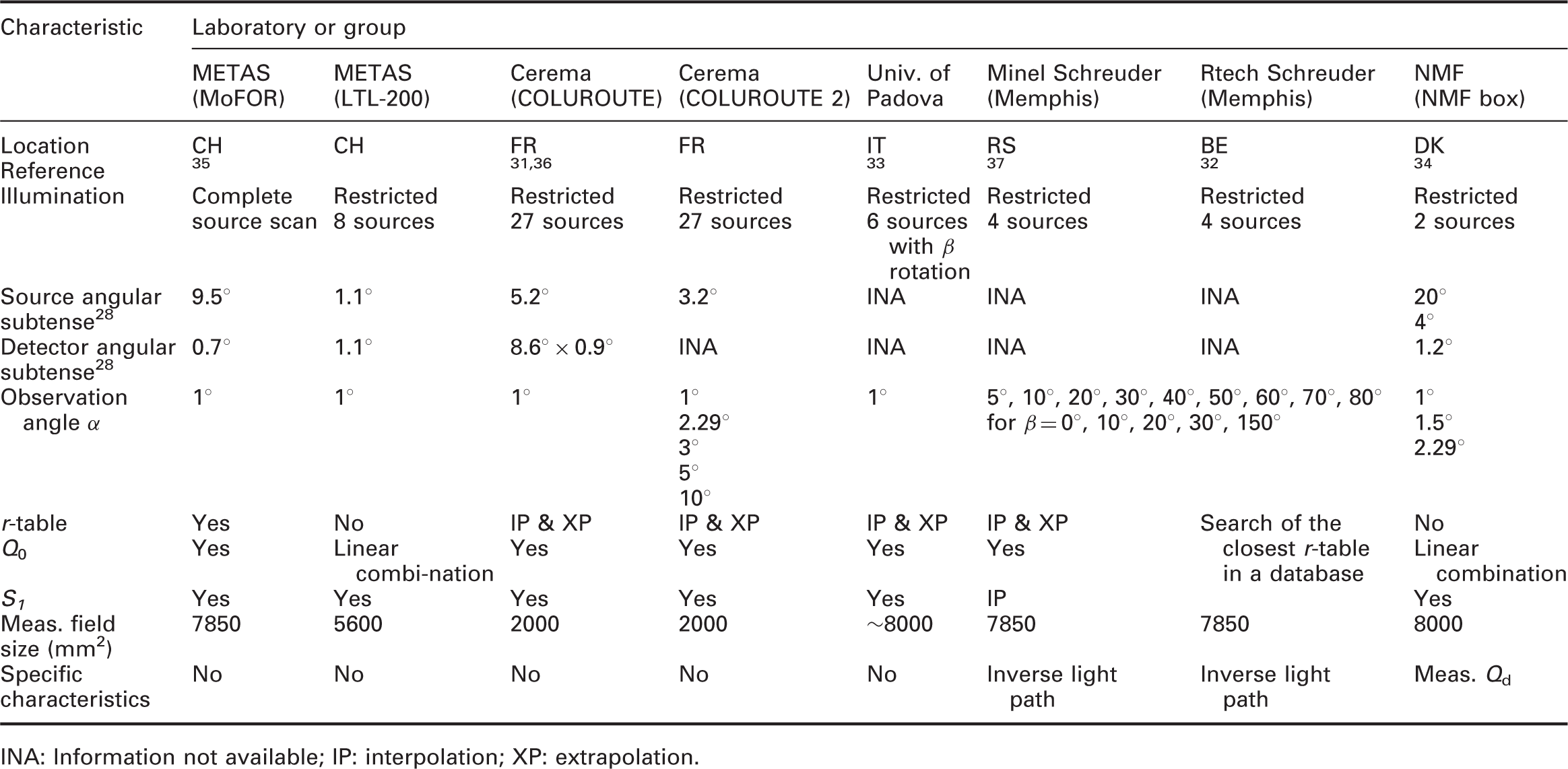
INA: Information not available; IP: interpolation; XP: extrapolation.
These devices always involve some compromises on the measurements, either with restricted measurement geometry combinations, or with larger measurement uncertainties. The solutions adopted are very varied in their mechanical and optical solutions. Some devices measure using pre-determined illumination angle configurations.31–34 Other devices measure the full r-table but face other issues, like the restricted size, which makes it more difficult to obtain a highly collimated source (MoFOR). The size of the illumination field is often limited to a smaller area than the recommended 104 mm2. In that case, the solution proposed is to measure different spots on the surface until the sum of all the measured area is 104 mm 2 or higher.
Using restricted geometry combinations, the setup does not measure the full r-table. Only selected illumination angles (ɛ, β) are measured. These devices usually allow the measurement of the specular components directly, but not Q0. Some modelling, interpolation, and extrapolation are then used to retrieve the complete r-table and to compute Q0. 31 Sometimes, the measured data or the resulting modelled r-tables are used to find the closest measured r-table from a database based on measurements done with a laboratory instrument. 32 This approach avoids the discrepancies found between standard CIE r-tables, which were done on old pavement surfaces, and measurements done on roads with more recent pavement. However, it assumes that the characteristics of particular pavements are present in the database used. For another device, Q0 is estimated by a linear combination of two r-values, r(0, 0) and r(0, 2), which are the ones used for the specular factor. 34 The coefficients of the linear combination are found by applying a linear regression on a database of r-tables measured with a laboratory instrument. However, due to the small number of measurement points, this method gives results that have a high standard deviation. The same method is applied to the measurements made with the portable device LTL-200 to find Q0 and S1, but using eight lamps.
Another portable measurement device developed in China measures Q0. directly in situ. 38 It uses a structured illumination, which reproduces the solid angle covered by the numerical integration. This is done by using a sphere with diffuse reflective properties and by painting black the areas which do not contribute to the overall integral, thus determining the integration boundaries.
The devices are also used in various ambient lighting conditions. They therefore utilise different solutions to avoid stray light. Solutions adopted range from blocking light from the environment with a box and measuring the dark signal, to using a modulated signal and synchronous detection. 31
The main advantage of portable devices is that they allow non-destructive measurements. This means that the evolution of pavements can be studied over a long period of time14,36 and that this information can be used to make lighting more efficient, by planning a well-suited lighting solution and by using dynamic adaptive lighting. 39 Portable devices can evaluate the heterogeneity of the photometric characteristics of the road surface and, for example, make many measurements on the wheel and central parts of a lane. So, despite being generally less precise, they are more representative of the actual road photometry.
5. Use of new geometries for the definition of road lighting design
5.1 Literature review regarding geometry
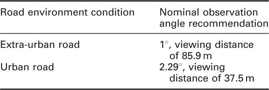
The geometry currently used with an observation angle of 1° for the design of pavement lighting was defined in the 1970s and confirmed in 1982, 13 2001, 14 and 2019. 17 In these CIE documents and in the road lighting standard EN 13201-3, 3 the height of the eye of the observer is set at the nominal value of 1.5 m. In the same standard, the range of observation angle is conventionally assumed to be 1.0 ± 0.5° according to a viewing distance between 60 and 160 m.
Concerning the characterisation of road markings, other geometries are defined in the standard EN 1436.
40
The eye of the observer is set at the nominal value of 1.2 m and the angle of observation is 2.29°, which corresponds to a distance of observation of 30 m. In the road marking standard, the tolerance on the observation angle is ±0.05°. The coefficient of retroreflected luminance RL corresponds to the night visibility of the marking, with an illumination angle of 1.24° (Figure 2(a)).
Schematic representations of the conventional geometry for the photometric characterisation of road markings according to EN 1436, which defines a nominal observation angle of 2.29° corresponding to an observation distance of 30 m and a driver’s height of 1.2 m. (a) Geometry for the measurement of the retroreflection factor RL: the illumination angle is set to 1.24°. (b) Geometry of the measurement of the luminance coefficient under diffuse illumination Qd. The integrating sphere creates a diffuse illumination from the light source placed in the middle of the sphere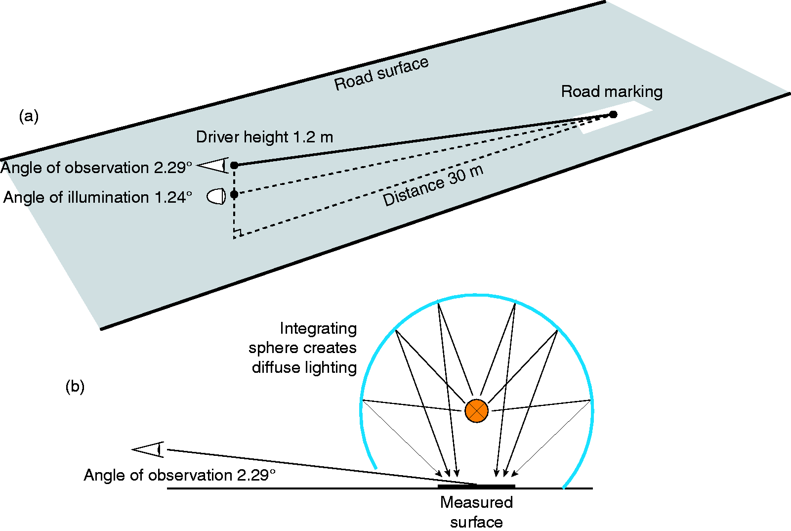
The luminance coefficient under diffuse illumination Qd (equation 6) was developed for road markings but could be also relevant for road surfaces.14,40 Qd is defined as the quotient of reflected luminance at 2.29° under diffuse illumination (Figure 2b). It is the average of the luminance coefficient weighted by cos ɛ integrated over the complete hemisphere above the road surface.
(a) Example of a luminance image taken with a luminance camera. The areas corresponding to different angles of observation are shown.51 (b) Corresponding luminance measured with the concept of a moving observer49,51 Theoretical model for light pollution evaluation of the light emission of town56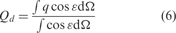

In the 1990s, Sorensen 41 suggested using Qd instead of Q0 for road lighting specification. At that time, both were measured at a nominal observation angle of 1°. A method to compute Qd from an r-table was given. 41 A device able to measure Qd and Q0 was developed 41 having an observation angle of 1.37°. The calculation of the average luminance and illuminance ratio in a typical lighting installation with two different lamp settings for the standard r-tables defined in CIE 06615 was compared 29 to the values of Qd and Q0. For the two road lighting installations used, Qd gave the best estimate of the average luminance with discrepancies between 0% and ±8% for Qd and an underestimation with Q0 from −12% to −39%. Brusque and Carta 42 made the same comparison with 12 lighting installations and the measured r-tables of 164 different pavements from R1 to R4: The mean discrepancy was between −2% and −13% for Q0 and between −13% and −41% for Qd. The results obtained were always better when using Q0 and showed that the Qd factor underestimates the specular effect and that differences are larger for grazing angles.
After these studies, the CIE publication 14414 confirmed the observation angle of 1° and the use of Q0 for pavement characterisation and an observation angle of 2.29° for road markings.
Gibbons 43 used a four-angle gonioreflectometer to study the influence of different observation angles on 20 core pavements with α = 1°, 2°, 3°, 5°, 7°, 10°, 12°, 15°, 20°, 30°, 45° and 90°. It was shown that the lightness of the pavement changes with the observation angle and that, except for the smaller observation angles, the specularity decreases with the observation angle.
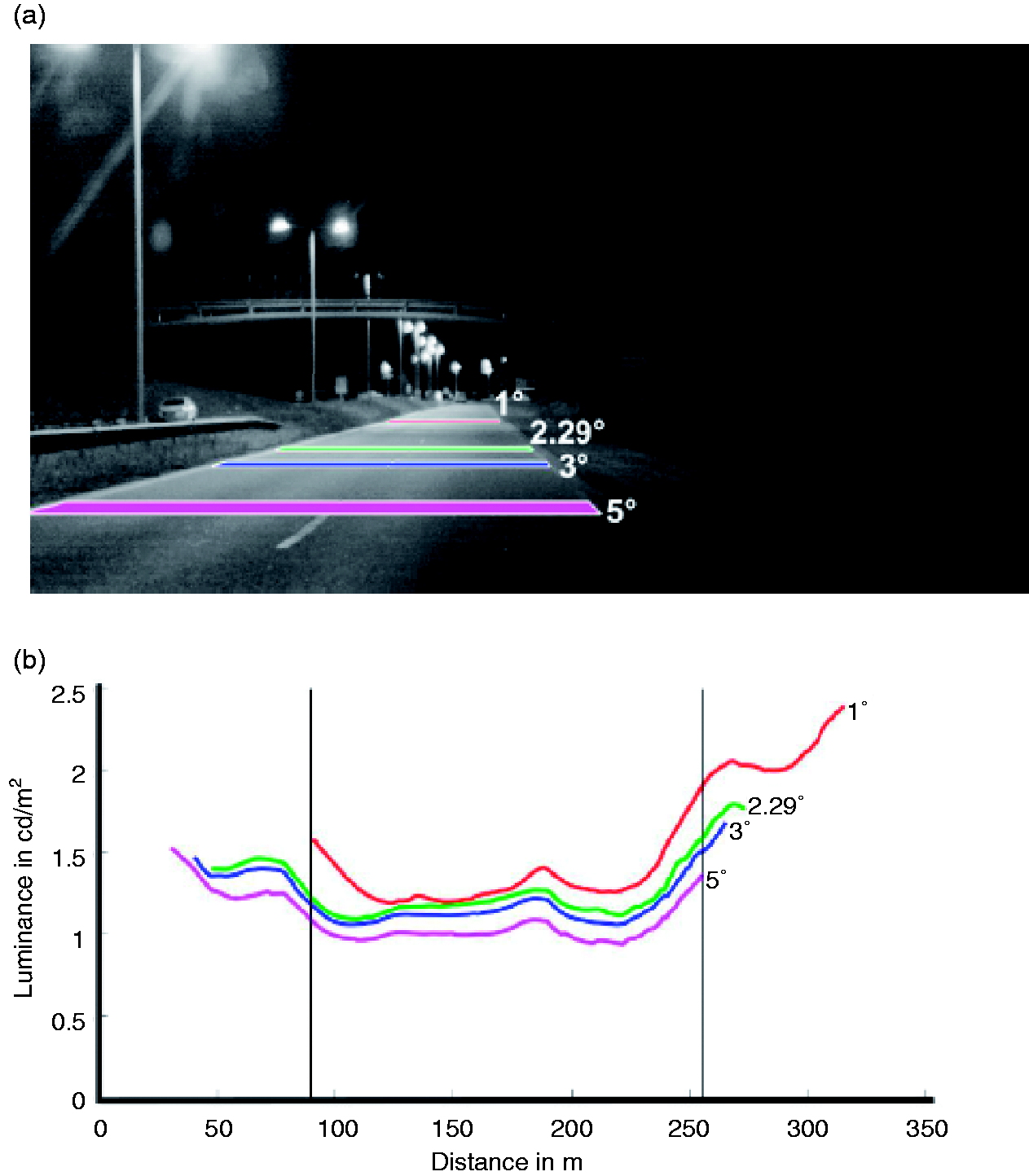
In more recent literature, a suggestion of different observation angles was made by Chain and Marchaut. 44 These were 90° for the characterisation of light from airplanes, 3° for urban applications, 10° for cyclists and pedestrians and 45° for visually impaired people. Some oculometric studies45,46 show differences in visual strategy of cyclists as a function of age, but none of them propose a preponderant angle of observation. Patla and Vickers 47 have shown that when a walker is required to step on specific locations in the travel path during locomotion, he looks on average two steps ahead. This result was confirmed by Fotios and Uttley 48 who found using eye tracking that obstacles are detected approximately 3.4 m ahead, thus corresponding to an observation angle of 27° if the eye is at a height of 1.5 m.
Stockmar 49 also suggested an angle of 3°, more adapted to urban applications. In his study, he indicates that the use of an observation angle of 3° instead of 1° induces a 10% reduction of Q0. Sorensen et al. 50 has developed a device able to measure at 1°, 1.5°, and 2.29°. The first results on a class R2 pavement show that the impact on Q0 and S1 is weak, especially for Q0 (and Qd). The specular factor S1 drops with increasing angle.
In the Greffier case study, 51 the impact of using observation angles of 2.29°, 3°, and 5° was studied with a mobile luminance camera. The luminance and uniformities were calculated according to the EN 13201 mesh grid, using the concept of a mobile observer proposed by Stockmar. 49 The first results show that the luminance decreases with an increase of the observation angle.
For visually impaired people, the observation angle is set at 45° in the standard concerning pedotactile caution warning devices. 52 The eye of the observer is also set by convention at 1.5 m.
Concerning the impact of light pollution on astronomical observation, no specific angle is given in the CIE document. 14 However, according to the experience of astronomers,53–55 the artificial sky luminance is mainly generated by the luminous flux, emitted directly by the luminaires and reflected by the illuminated surfaces, within the range of elevation between 0° and 20° over the horizontal plane. At such elevations, the light travels in the low levels of the atmosphere, where the aerosols generate downward diffusion into the entrance pupil of a telescope and a sort of veiling luminance in the star observation direction. This reduces the contrast of the heavenly bodies since it adds to the natural sky luminance. Upward light with elevations higher than 20° travels in higher layers of the atmosphere, where aerosols are not present, and generates a much lower downward diffusion.
A town can be treated as a single uniformly diffusing source; 56 most luminaires are hidden in cavities between buildings and few luminaires are not screened by buildings (typically on the boundary of the town or in large open areas). The road surface behaviour for light pollution is similar: light reflected by road at angles between 0° and 20° over the horizontal road plane have higher impact on astronomical observations too. Unfortunately, these angles are very close to the lighting angles (up to 70° to 75° from the vertical) that provide lighting efficiency. Furthermore, to reach these grazing angles using discharge lamp sources entails some upward direct light (about 2–3%) from the luminaires. Only certain LED luminaires satisfy standard specifications on zero upward flux. But one shall keep in mind that light pollution and energy consumption are related to the illuminance on the road,11,57 while visibility and safety are directly linked to the luminance measured along the observation direction.
In calculations of obtrusive light and in particular for the calculation of the upward flux ratio, 58 the reflectance of the road is the ratio between the incident illuminance and the reflected illuminance measured at 1 meter height. 59 It should be mentioned that examples of different surface reflectance are based on measurements done in the 1990s and have not been updated since then.
5.2 SURFACE project analysis
Concerning the illumination angles, there is a need for more data at grazing angles due to the use of guide lighting devices mounted at low heights, especially in tunnels. Since the r-table is only defined up to tan ɛ = 12, when the mounting height of the luminaires is very low (H < 2 m), an extension for tan ɛ is needed. For this reason, in EN 13201-33 the informative annex B defines an extended r-table format for luminaires with low mounting height. The r-table is extended in tan ɛ up to 20, by increment of 0.5 for every β angle. However, there is still a need for such data and a new calculation of Q0 should be proposed to take this table into account. However, up to know, it seems that nobody is able to make measurements at such grazing angles. The main reason is the required very small angular subtense of both the detector and the source.
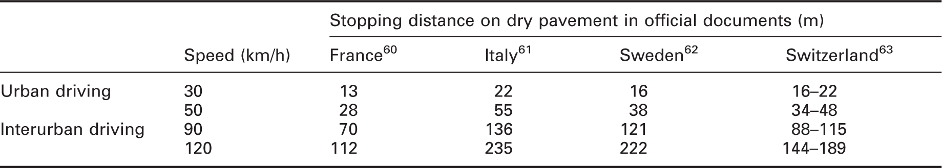
Concerning the observation angle, it is affected by both the vehicle type and the distance of observation. For drivers of motorised vehicles, in the EN 13201 standards, the main lighting criteria for interurban driving are based on the road surface luminance and include the average luminance, the overall uniformity and the longitudinal uniformity. The driver’s eye is assumed to be at the nominal value of 1.5 m above the road surface and the angle of observation is fixed to 1° below the horizontal, corresponding to a distance of 86 m ahead of the observer. This geometry is well adapted for a speed of 90 km/h, on motorways for example. However, nowadays, except in tunnels, there are few interurban lighted roads in Europe. Illuminated areas are located in urban environments where there are several types of road users (vehicle drivers, but also cyclists and pedestrians), travelling at different speeds. To define new observation angles, a first approach is to consider the stopping distance, which is a summation of the reaction distance and braking distance. Typical stopping distances in Europe are presented in Table 3. For road safety, good visibility of obstacles within the stopping distance is very important.
Stopping distance at different driving speeds (according to the authors’ country driving code)
Distances which correspond to different nominal observation angles at 1.5-m height of observer

SURFACE recommendation for new geometries
To improve astronomic observations, a reduction of the prescribed values of road illuminance, and for zones close to observatories also of the luminance value, is required. But the safety of road users must be ensured by alternative means and strategies, like higher lighting levels at intersections and on pedestrian crossings, very low mounting-height luminaires and new visibility models.
As shown in Tables 1 and 2, some measurement devices are already able to measure at the new angles of observation and some are under development among the SURFACE consortium. Using lower grazing angles has several advantages because the design tolerance on the angles is less critical, and thus it is possible to construct more compact instruments. Moreover, existing devices used for the characterisation of road marking could also be transformed to measure road surface photometry. This is why these new geometries allow the development of less expensive measurement devices and an increased accuracy also for on-site verification.
6. Conclusion
The SURFACE project has, during its duration, produced an extensive international review on road photometry, including measurement devices, available data, measurement methods, and national reference values for lighting design. 11 In addition, SURFACE investigated current geometries for road surface characterisation and road user conditions of viewing, and is able to suggest to international normative bodies (CEN and CIE) these findings and new approaches.
Regarding geometries, the first evidence is about the most critical point of the current approach; the reference observation angle currently used in standard. The difficulties of making measurements at 1° observation angle are already recognised in literature,14,44 but SURFACE has highlighted and substantiated these issues and also proposed solutions. The large literature review and investigation among the SURFACE consortium and stakeholders allow us to suggest referencing normative bodies (CIE and CEN) the use of different geometries according to actual road environment. We recommend keeping the angle of 1° for extra-urban environment and propose new observation angles for different driving conditions and road users. SURFACE suggests additional nominal observation angles of 2.29° for urban environment and consistency with the road marking standard and CIE 144, 5° for urban driving at low speed, cycling and scooters, and also 10° or 20° for light pollution impact evaluation for which investigations are ongoing. These several possible observation angles are proposed to be included at the earliest review stages of CIE 144 and EN 13201 documents.
The impact of the above new geometries for road surface characterisation needs to be verified by lighting design programs, simulation tools and subjective experiments. The same geometries have to be used at design stage and at on-site verification of compliance.
Some measurement devices for road luminance coefficient evaluation can be easily adapted to the new angles of observation and others are going to be introduced in the market (also among the SURFACE consortium). Furthermore, these new geometries allow the development of less expensive measurement devices and an increased accuracy also for on-site verification. The geometrical constraints of 1° of observation entail difficulties in setup and increased alignment discrepancies. It also affects on-site verification, the identification of measurement grid points, and associated luminance values.
The findings of SURFACE also impact the energy consumption; SURFACE confirmed the advantages of using bright pavements and smart lighting. 11
Additional impact is expected on the luminance levels required for the different road lighting classes; the current reference values are based on results of visual experiments carried out in the past century on contrast threshold at 1° observation angle and using old pavements.
The definition of new angles of observation will have an impact on the required threshold luminance levels of uniformity. New subjective experiments are needed in order to define new reference values of contrast threshold to acknowledge not only the new recommended geometries, but also current pavements, including bright ones, LED sources, 3D objects detection (instead of 2D shapes as used in the past), and the concept of a moving observer. All these new additional aspects need to be tested: a full approach to road-lit environment, including observer (human or machine) is necessary to maximise the effects and to reach the target of EU Vision Zero – to reduce road deaths to almost zero by 2050. The effect of all these aspects need to be tested: the research is just at an early stage with the SURFACE project.
Footnotes
Declaration of conflicting interests
The authors declared no potential conflicts of interest with respect to the research, authorship, and/or publication of this article.
Funding
The authors disclosed receipt of the following financial support for the research, authorship, and/or publication of this article: This work received funding from the EMPIR programme, project ‘16NRM02 Surface Pavement surface characterisation for smart and efficient road lighting’. 12 The EMPIR (European Metrology Programme for Innovation and Research) programme is co-financed by the Participating States and from the European Union’s Horizon 2020 research and innovation programme EURAMET (EURopean Association of national METrology Institutes). SURFACE is a consortium of six National Metrological Institutes, of Italy, Estonia, France, Finland, Sweden, and Switzerland, plus a National French Research Centre (Cerema) and two industrial companies (Proceq, measuring instruments and Ansys-Optis, software simulation). It has the support of CEN, CIE and National Standardisation Organisations, road authorities, as well as a group of more than 40 stakeholders.