
Abstract
This paper uses data regarding detection of pavement obstacles to explore two approaches to establishing an appropriate illuminance for road lighting designed to meet the needs of pedestrians. A previous obstacle detection experiment was repeated using young observers under high pressure sodium (HPS) lighting. One approach was to identify whether there is a plateau-escarpment relationship between obstacle detection ability and illuminance – better detection with increasing light level until further increases bring little improvement: This suggested an appropriate illuminance of 5.7 lux. The second approach was to identify the size of an obstacle that a pedestrian should expect to be able to detect and the associated probability of detection: An obstacle of height 25 mm located 6 m ahead may require 1.8 lux to be detected with 95% probability.
1. Introduction
This paper discusses data that might be used for establishing appropriate light levels for residential roads.
European Standard EN 13201-2:20031 provides guidance for road lighting in two situations: The ME classes are for traffic routes of medium to high driving speeds, and the S classes are for footways, cycleways, emergency lanes and other road areas lying separately or along the carriageway of a traffic route, and for residential roads, pedestrian streets, parking places, schoolyards etc. British Standard BS 5489-1:2003 2 identifies the ME classes to be for motorways and traffic routes and the S classes to be for subsidiary roads. This paper pertains to residential roads which are thus a type of subsidiary road and for which the series of S classes is intended. In residential roads, it is normal to provide lighting that focuses more, but not exclusively, on the needs of pedestrians compared to those of drivers. 3 Minimum average illuminances for residential roads are defined by the S-series of six lighting classes which range from 2.0 lx to 15.0 lx.1,2
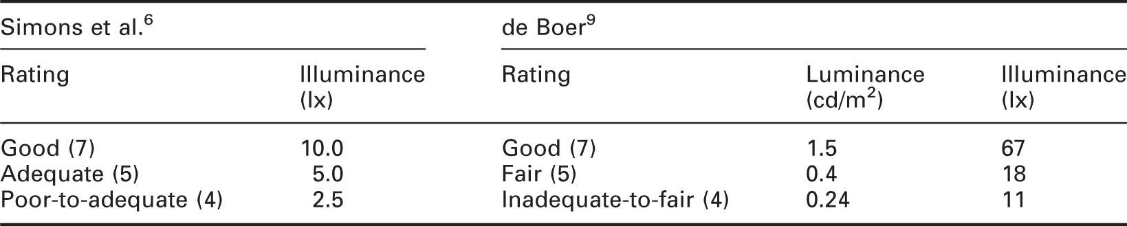
The S-series is an amalgamation of the lighting classes used in European countries prior to 2003. The UK had previously used three classes of lighting 4 and the validity of these three illuminances has been questioned. 5 For exterior illumination, BS5489-3:1992 4 specified minimum average illuminances of 3.5 lx, 6.0 lx and 10.0 lx for subsidiary streets, according to the level of crime risk and the vehicular and public use of the area. These illuminances were based on the study reported by Simons et al. 6 which comprised two field surveys of road lighting. In the first survey (London), 13 observers rated their satisfaction with the lighting in 12 streets using a rating scale, and this was followed by a second survey (Milton Keynes) of 12 streets by 20 observers. In both cases, the average horizontal illuminances ranged from about 1.0 lx to 12.0 lx. A nine-point rating scale was used, with points labelled very poor (1), poor (3), adequate (5), good (7) and very good (9) and the items rated included an overall impression and levels of lighting on the road and footpath. The results suggest that higher illuminances lead to higher ratings of overall impression. Horizontal illuminances of 10.0 lx, 5.0 lx and 2.5 lx were subsequently proposed, as these corresponded to ratings of good (7), adequate (5) and poor-to-adequate (4) respectively.
These results are not surprising. When observers are asked to make judgements about a range of sensory stimuli, they tend to rate the stimuli against each other rather than against a consistent reference stimulus – this is clearly seen in the brightness judgements of Teller et al. 7 and the loudness judgements discussed by Poulton. 8 Therefore, when rating lighting ranging in illuminance from 1.0 lx to 12.0 lx, it is not surprising to see lighting of 1.0 lx being rated near the bottom end of the scale and lighting of 12.0 lx being rated near the top of the scale. If a different range of illuminances had been surveyed, say 0.5 lx to 5.0 lx or 5.0 lx to 50.0 lx, then it is likely that different illuminances would correspond to ratings of good, adequate and poor-to-adequate, and thus a different set of average horizontal illuminances would have been proposed.
de Boer 9 and de Boer et al. 10 also report a study carried out in 70 real streets. A 9-point rating scale was used, with points labelled bad (1), inadequate (3), fair (5), good (7) and excellent (9), similar but not identical to the scale subsequently used by Simons et al., and the items rated included level of lighting on the road. The road luminances ranged from approximately 0.06 cd/m2 to 5.0 cd/m2 which is an illuminance range of approximately 2.7 to 224 lx assuming a road surface reflectance of 0.07. The ratings display a positive correlation with luminance: The low-luminance roads are placed near the bottom of the rating scale, while the high-luminance roads are placed near the top of the rating scale.
The ranges of illuminances used for residential roads in other countries do not match those used in the UK. Compare, for example, the criteria used in the UK with those for Australia and New Zealand and for Japan. The S-series of average illuminances used in the UK ranges from 2.0 lx to 15.0 lx, whereas for local roads in Australia and New Zealand,11,12 average illuminances in the P categories extend across a range of 0.5 lx to 7.0 lx and in Japan13,14 the recommendations for residential roads provide for average illuminances of 3.0 lx to 5.0 lx horizontally on the pavement. If the standards in these different countries were made with the same assumptions of visual needs, this would suggest that illuminances have been chosen for reasons other than to meet visual needs. The current article therefore aims to identify evidence related to visual tasks by which light levels in residential roads might be established.
One past study has provided evidence for setting a minimum illuminance and this was based on perceived safety. Boyce et al. 15 carried out field surveys of 24 car parks in urban and suburban areas in New York and Albany in the US to investigate how the amount of light affected the perception of safety at night. Test participants were transported to the sites in four vehicles and these visited the sites in different orders in both daytime and night-time. The car parks had mean horizontal illuminances of up to 50 lx. At each site, they were asked to walk around and then describe lighting using questionnaires comprising a series of semantic differential ratings scales and open questions. One question sought ratings of perceived safety when walking alone. Two interesting findings were reported. First, walking at daytime was perceived to be safer than walking in night-time: lighting at night was able to bring the perception of safety close to that of daytime in a small number of sites but did not exceed it. Second, as illuminances increased, the difference in ratings of perceived safety for daytime and night-time tended to decrease. The relationship between illuminance and perceived safety appears to be non-linear. At low illuminances (0–10 lx), a small increase in illuminance produced a large increase in perceived safety; at high illuminances (≥50 lx) increases in illuminance have negligible effect on perceived safety; and in the intermediate range (10–50 lx), the increase in perceived safety with increases in illuminance follows a law of diminishing returns. The Boyce et al. study therefore suggests a minimum illuminance of approximately 10 lx: higher illuminances lie on the plateau and therefore do not bring any benefit in terms of improvement in perceived safety, while illuminances lower than 10 lx are on the escarpment and may lead to a significant reduction in perceived safety. Further work on perceived safety is being carried out to examine whether this conclusion is appropriate for residential roads in the UK. 16
The setting of light levels needs also to consider the further visual tasks of pedestrians in residential roads that contribute to safe movement and perceived safety. This paper reports two possible approaches to identifying minimum illuminances using data from investigation of obstacle detection. An obstacle is an approaching object or irregularity such as a raised paving slab that may cause a pedestrian to trip, or is not noticed in time to avoid collision – a potential safety hazard: Road lighting must provide for adequate obstacle detection as a countermeasure to trip hazards and collisions. The first approach used in this paper seeks a threshold point in the illuminance versus performance relationship. The second approach is based on a legal interpretation of what defines an obstacle and thus what a local authority may expect lighting should be able to do to assist a pedestrian.
2. Threshold illuminance
2.1. Previous work
At photopic light levels, the relationship between luminance and relative visual performance (RVP) exhibits a plateau and escarpment form. Visual performance is the speed and accuracy of processing visual information and this is affected by properties of the task and of the illumination. RVP is a model for predicting changes in visual performance associated with changes in light level, task contrast and task size, and this suggests that a visual task becomes easier to perform by increasing its size so that detail is easier to discern, by increasing its contrast against the background and by increasing the background luminance.17,18 These three factors exhibit a plateau and escarpment relationship with visual performance. At low task sizes, low contrasts and low luminances, a small change in either one of these may lead to a large change in visual performance, the escarpment region. However, at higher task sizes, contrasts and luminances, a change leads to negligible effect on RVP; this is the plateau region.
Previous work has investigated obstacle detection at the mesopic light levels typical of lighting in residential roads.
19
The results of this study are summarised in Figure 1, this being the obstacle height required for a 50% detection probability and thus a smaller height in Figure 1 denotes better obstacle detection ability. It can be seen that obstacle detection is affected by type of light source, illuminance, and age of observer. Of interest to the current article is that Figure 1 displays a plateau-escarpment relationship between illuminance and obstacle detection. If these data are appropriate, they suggest a threshold illuminance of around 2.0 lx: higher illuminances lie on the plateau and may not bring a significant improvement in obstacle detection while illuminances lower than 2.0 lx are in the escarpment region and may lead to a significant reduction in obstacle detection.
Mean obstacle height for the 50% detection probability plotted against illuminance to show obstacle detection ability of older and younger observers under different illuminances for one high pressure sodium (HPS) lamp (SON) and two types of MH lamp (CPO and CDO).
19
The primary (left-hand) y-axis shows the heights of obstacles in the test apparatus. The secondary (right hand) y-axis shows the approximate height (mm) for real obstacles assuming a standard eye height of 1.5 m above the floor. The lamp scotopic/photopic (S/P) ratios (measured within the test apparatus) were 0.6 (SON), 1.2 (CPO) and 1.8 (CDO). Measured data points for each combination of light source and observer age are linked by straight lines of obstacle detection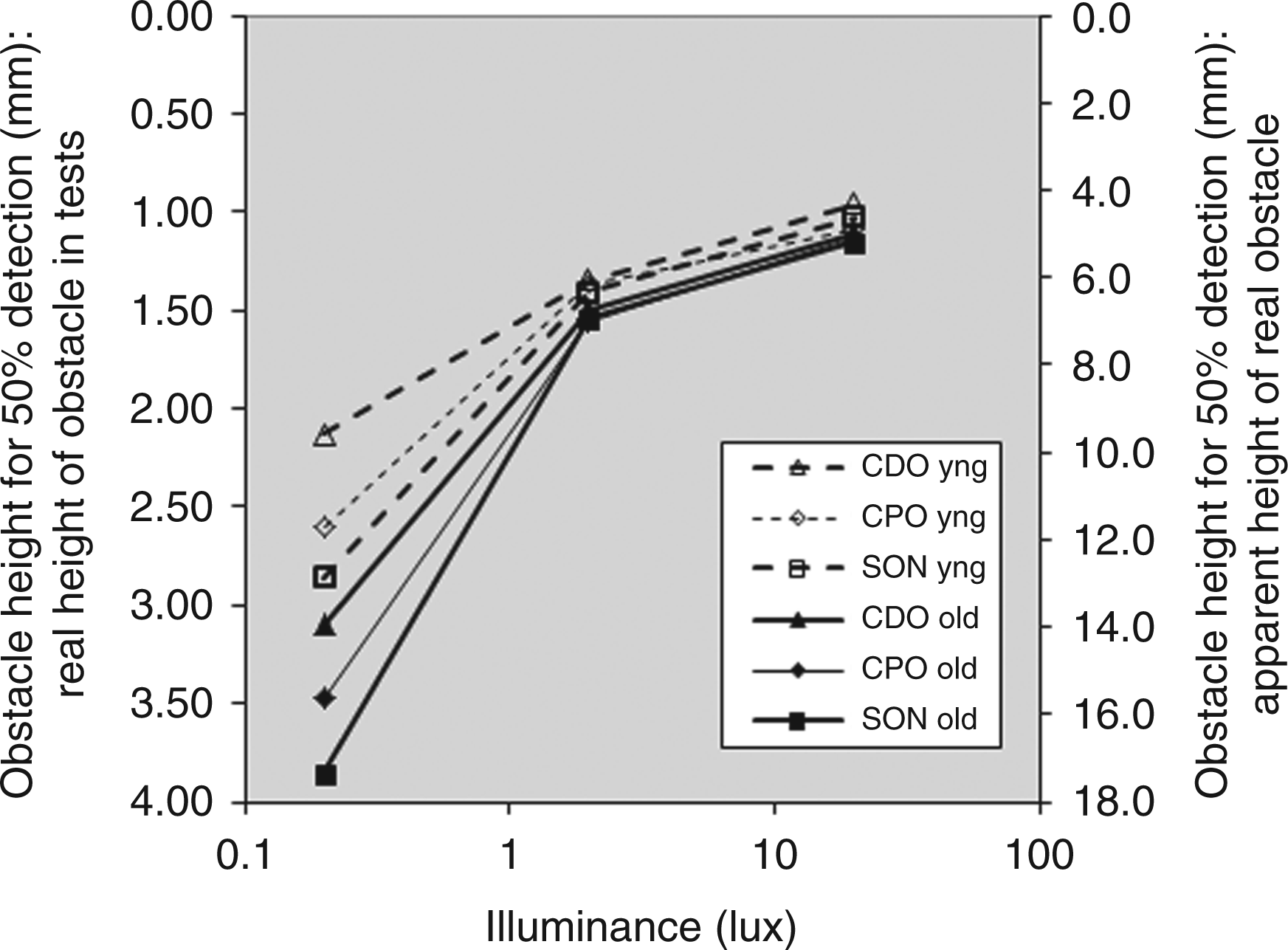
It is possible that the apparent plateau-escarpment relationship is an artefact of a graph drawn using only three data points: For each combination of lamp type and observer age in Figure 1, there are only three data points, corresponding to the three reference illuminances (0.2 lx, 2.0 lx and 20 lx) and a change in any one of these points could change the apparent relationship. However, the fact that each of the six lines displays a similar trend suggests that the plateau-escarpment relationship is real.
A further test was therefore carried out to establish whether the plateau-escarpment relationship shown in Figure 1 is repeatable and this experiment included two further reference illuminances to interpolate between those used in the previous study.
2.2. Method
Obstacle detection was examined using the same apparatus and methodology as in the previous study.
19
The apparatus comprised a booth, the interior of which was lit from above and was viewed through a small aperture in the front screen (Figure 2). The floor, of dimensions 1200 mm × 1080 mm, comprised a 10 × 9 array (width × depth) of cylindrical blocks. The upper surfaces of these blocks were normally flush with the surrounding floor but could be individually raised by incremental amounts using stepper motors, thus providing a surface irregularity – a target obstacle.
Side elevation of apparatus with left-hand side panel removed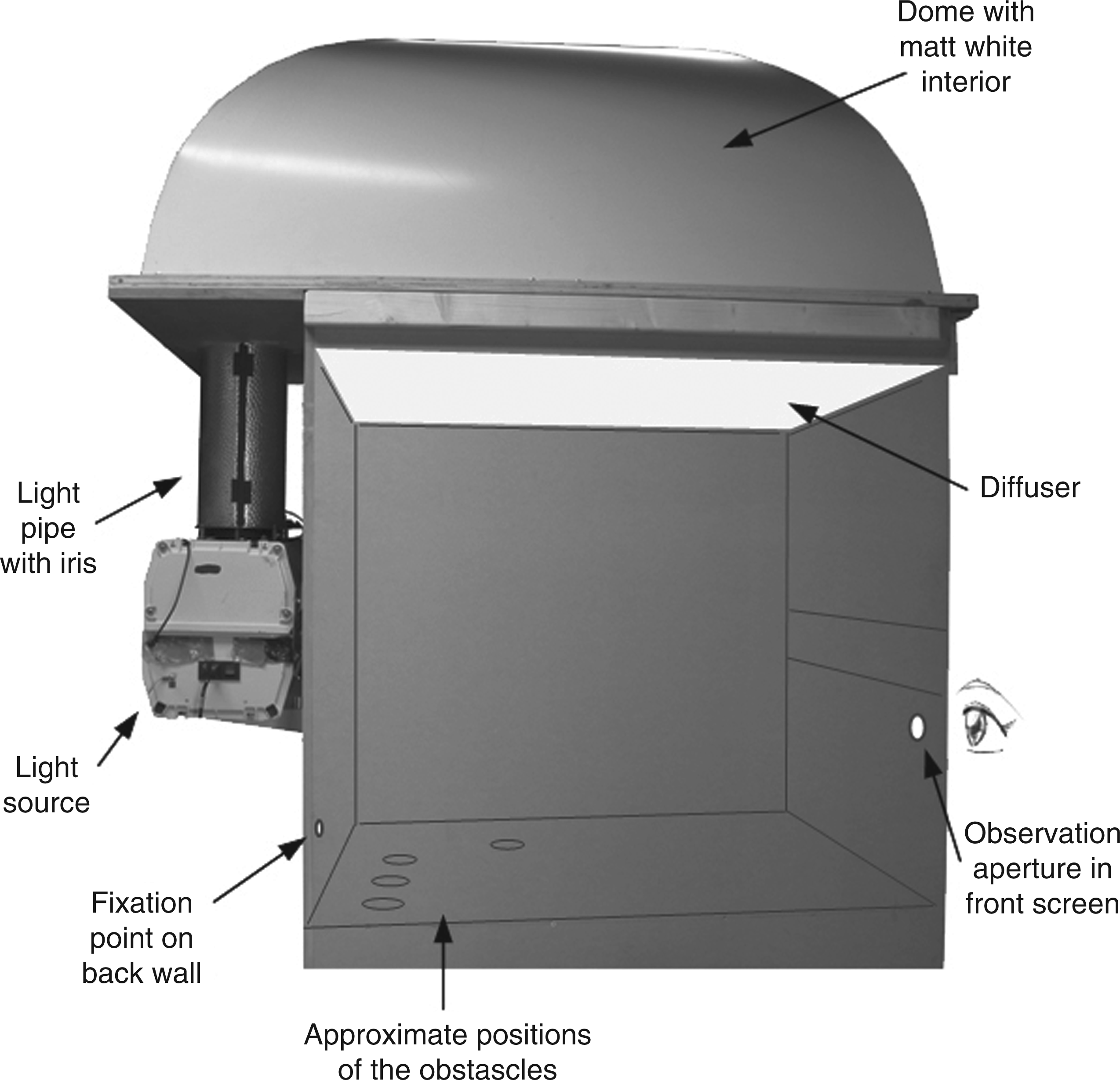
The light source was hidden from direct view, with light transported into the booth using an internally reflective pipe, and the interior of the booth was lit by reflection from the ceiling of the booth. An iris in the pipe enabled the lighting to be dimmed without affecting the spectral power distribution (SPD). The ceiling of the booth, which had a matt white finish, approximated a hemisphere to promote an even distribution of luminance across the floor of the booth, and this was further aided by a diffusing filter fitted above the viewing chamber. The interior surfaces of the booth visible to observers, including the top and sides of the cylindrical obstacles, were painted with a grey paint (Munsell N5) of diffuse reflectance (r = 0.20).
The interior of the booth was viewed through an aperture in the front screen. For each trial the aperture was opened for 300 ms. This exposure time was chosen because visual information is acquired from the outside world during the inter-saccadic intervals (fixational pauses or glimpses), the duration of which is approximately one third of a second. 20 If it is considered that the information gained by the visual system in successive inter-saccadic intervals is not independent, but rather that the visual system builds upon what is seen during each glance to construct a global image of the external world, then the equivalence of a 300 ms viewing time to the inter-saccadic intervals is only partially valid. However, there is a large body of research which demonstrates that this is false; participants cannot integrate sensory information presented on separate fixations. 21
The aperture was placed on the left-hand side of the front screen and all obstacles were thus straight ahead or to the right-hand side. A fixation point was fixed to the rear wall of the booth presenting a visual size of approximately 57 min. arc at the eye of the test participant. This was a white paper disc, back-illuminated by fibre-optic cable connected to the light box and hence having the same SPD as the test light source. Visual space is mapped using peripheral vision 20 and therefore this research was designed to investigate obstacle detection in peripheral vision. 19 Note that subsequently it has been found that peripheral vision is sufficient for precisely guiding foot placement during obstacle navigation. 22
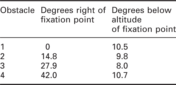
The location of the obstacles, being projections raised from the floor of the booth, was intended to represent an irregular pavement surface, e.g. a raised paving slab. The obstacles were presented in four different positions, 1 to 4 in Table 2 and Figure 3. These were approximately equidistant from the observation aperture, and hence presented targets of similar shape and size.
Plan of the obstacle detection test booth to show the location of the obstacles Obstacle positions from observation aperture relative to fixation point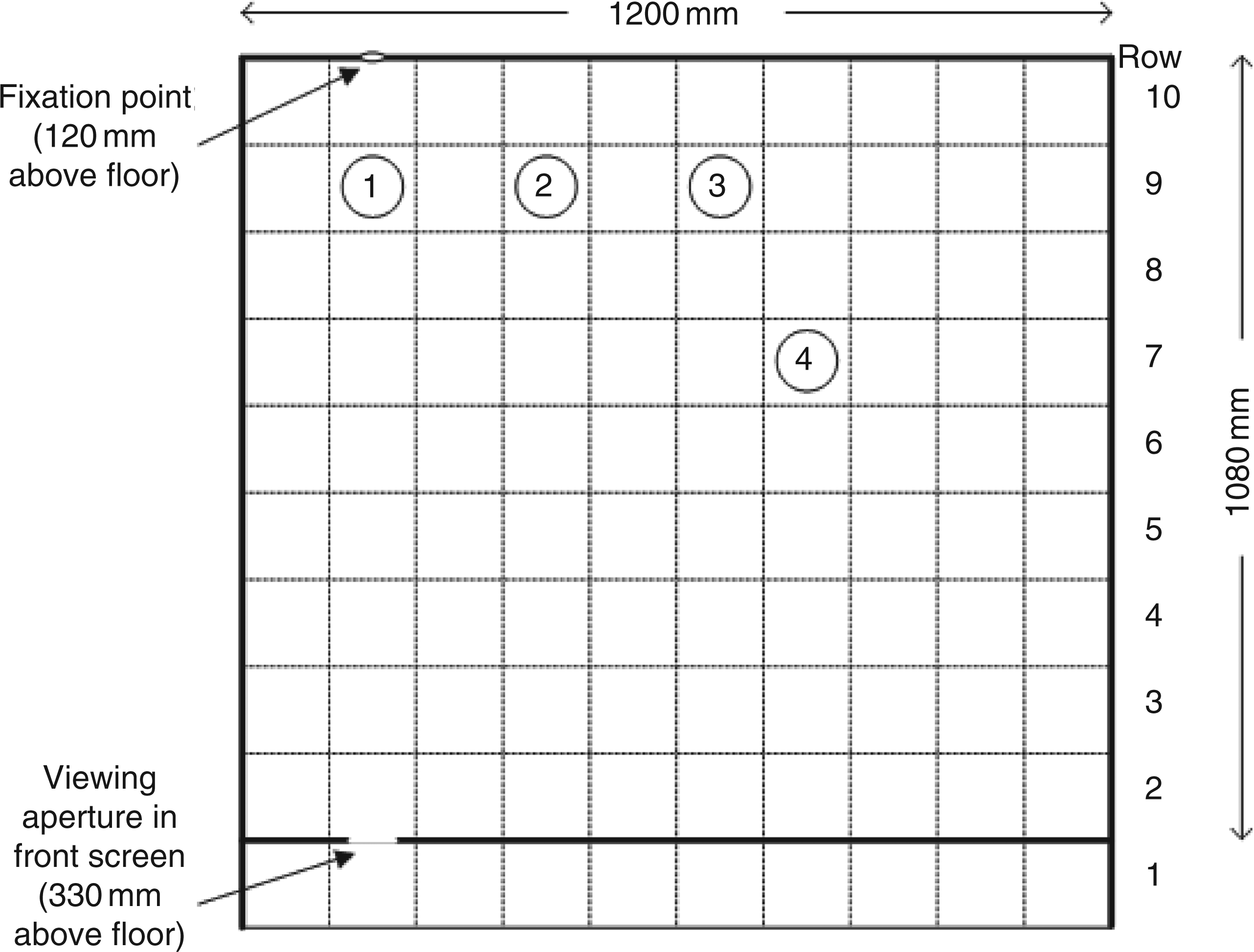
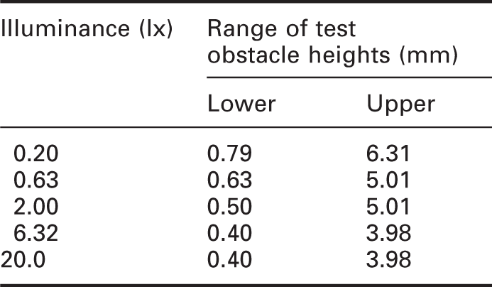
The aim of the current study was to verify the plateau-escarpment relationship between illuminance and obstacle detection found in previous work, and this was done using only one type of lamp and five illuminances. The lamp was a standard high-pressure sodium (HPS) lamp as was used in the previous study (2000 K, Ra = 25, scotopic/photopic (S/P) ratio = 0.57), this lamp being chosen because it suggested the strongest evidence for a plateau-escarpment transition in Figure 1. The five illuminances were 0.20 lx, 0.63 lx, 2.0 lx, 6.32 lx and 20 lx. The illuminance was set for every trial by the experimenter who adjusted the position of the iris in the light pipe with feedback from a Minolta T-10M illuminance meter.
Range of obstacle heights for obstacles 1–4 for each illuminance
Four young test participants were used, two males and two females, aged 18–34. This was a repeated measures design, and each test participant saw all 160 combinations of the five illuminances, four obstacle locations and eight obstacle heights. A further 40 null condition observations (eight per illuminance) were included in which none of the obstacles was raised, and this was done to identify the degree of false-positive reporting (false-alarm). These 200 observations were experienced in a randomised order, except that illuminance changes between trials were limited to two steps of the test illuminances, a maximum of one log unit, in order to reduce any effects of adaptation.
The test participant looked through the aperture with their right eye (the left was covered with an eye patch) and instructed to maintain their attention upon the fixation point located opposite the aperture on the rear wall. With the aperture closed, a single obstacle was raised. The choice of obstacle, the amount by which it was raised and the illuminance were randomly assigned. The aperture was opened for 300 ms, and the observer instructed to report if a raised block was present by stating its identification number (1 to 4) or to state ‘none’ if no raised obstacle was noticed. Each test participant was required to attend one test session of approximately 2 hours to complete the experiment. Twenty practice trials were carried out before the main test; a semi-randomised mixture of different blocks, heights, light levels and null conditions. Through this it was confirmed that the participant could accurately identify the four obstacle locations, and that it was appropriate to report the nil response when no obstacle was seen.
2.3. Results
An example of the test results is shown in Figure 4, this being for obstacle #1 at 0.63 lux for the four test participants combined. This shows the probability of detecting the obstacle when raised from the surface by a given height.
Sample test result: Detection probability (%) for obstacle #1 at 0.63 lx for the four test participants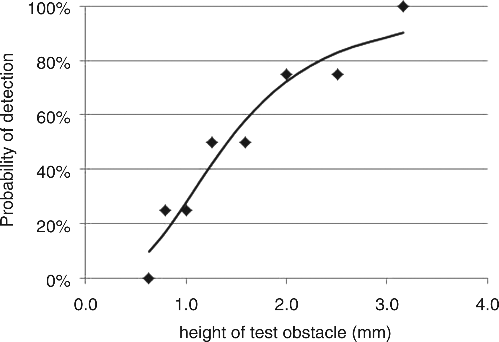
The data points in Figure 4 are the experimental results, the mean frequency with which an obstacle of a given height was detected. Following the previous study, initial analyses were carried out using a 50% detection probability. The curve in Figure 4 is the best fit curve as fitted using the Four Parameter Logistic Equation (4PLE). For the current analysis, the 4PLE can be expressed as shown in equation (1).
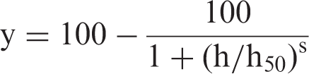
y = detection probability (%)
h = height of obstacle
h50 = height of obstacle at which y = 50%
s = slope of curve when h = h50
Test obstacle height for 50% probability of detection (h50) as determined using Four Parameter Logistic Equation fitted to the test results
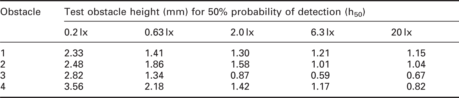
Figure 5 shows the overall effect of illuminance on obstacle detection. The data points are the mean detection heights (h50) for each illuminance averaged across the four obstacle locations. It can be seen that illuminance affects obstacle detection, with the height needed for 50% detection probability increasing as illuminance decreases.
Mean test obstacle height for 50% detection probability of obstacles 1 to 4 plotted against illuminance. Note: Smaller values of h50 imply better obstacle detection ability
Figure 5 also shows the results found in the previous study 19 for the young observers under the HPS lamp. For the three illuminances common to both studies, the obstacle heights for 50% detection probability are very similar, and this suggests that the results of the original experiment are repeatable.
2.4. Null condition results
The quality of the decisions made in this experiment can be evaluated through analysis of null condition data and by applying signal detection theory. Here, decision quality means how well test participants avoided making incorrect responses. Correct responses are hits, saying yes when a stimulus is present, and correct rejections, saying none when a stimulus is not presented; incorrect responses are false alarms, reporting the presence of an obstacle when none are raised, and misses, saying none when a stimulus is presented.
Detection performance found during the null condition and raised block trials. For each illuminance there were 40 null condition trials and 160 real trials
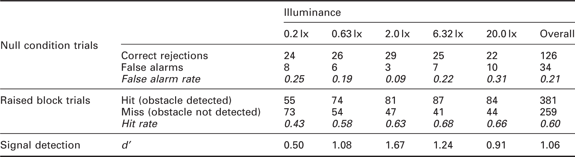
Response bias is the tendency to say yes or no when unsure of detecting a stimulus. This might be an error in favour of detecting all stimuli at the risk of making false alarms, or alternatively a cautious approach to the risk of making misses. An ideal observer would maximise the hit rate while minimising the false alarm rate and thus the larger the difference between hit rate and false alarm rate, the better the observer’s sensitivity. The sensitivity index (d ′) is a measure for analysing response bias and is the difference between the Z-transformations of the hit rate and the false alarm rate: Values of d ′ near zero indicate chance performance (no discrimination) and higher values d ′ indicate that the signal can be more readily detected. Values of d ′ for the current data (Table 5) are above zero in all cases, which suggests better than chance performance.
Thus, these data suggest that in the current experiment test participants tended to report detection of an obstacle only when there was an actual obstacle present and to report no detection when obstacles were absent.
2.5. Interpretation of threshold illuminance
Figure 5 shows the mean obstacle heights for a 50% probability of detection (h50) for each illuminance. The data suggest a non-linear relationship, with a larger change at lower illuminances and a smaller change at higher illuminances, although the two additional intermediate illuminances used in this new study indicate the transition is not as dramatic as indicated by the previous results.
The previous study 19 used the 50% detection probability to compare performance under different lamps. To estimate an optimum illuminance, an absolute value, requires consideration of this criterion. It may be expected that lighting should enable a higher detection probability than 50% and it is also possible that the detection curve shown in Figure 5 would change shape for different detection probabilities.
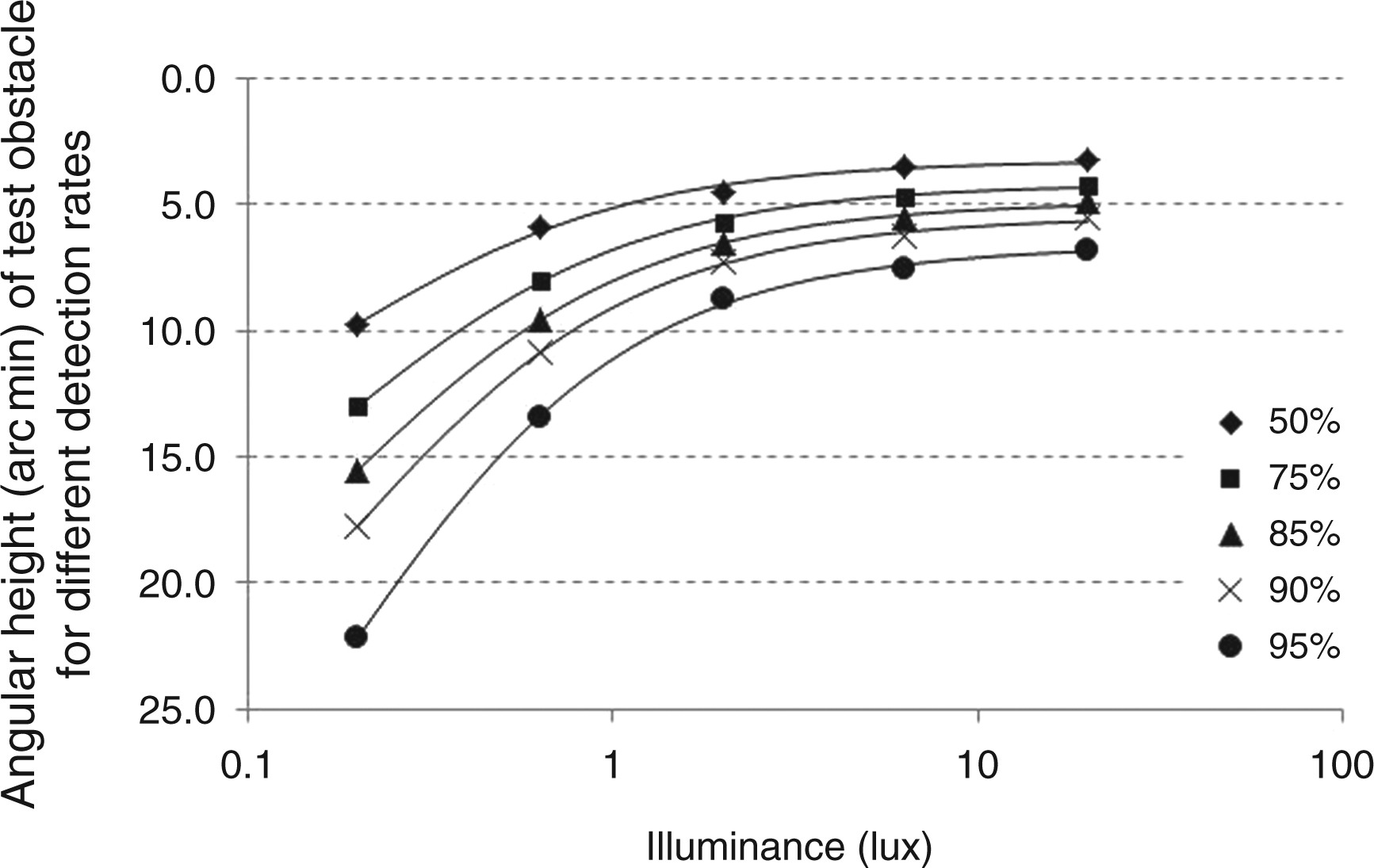
Figure 6 shows the obstacle height required for detection probabilities of 50%, 75%, 85%, 90% and 95%, as calculated from the current data using the 4PLE curve fitted to data for each obstacle and illuminance combination. It can be seen that, as expected, an obstacle needs to be higher to achieve a greater probability of detection. The 95% probability curve suggests a more pronounced plateau-escarpment relationship than does the 50% probability curve, with a knee in the region of 2.0 lx.
Mean detection heights of obstacles 1 to 4 for detection probabilities of 50%, 75%, 85%, 90% and 95%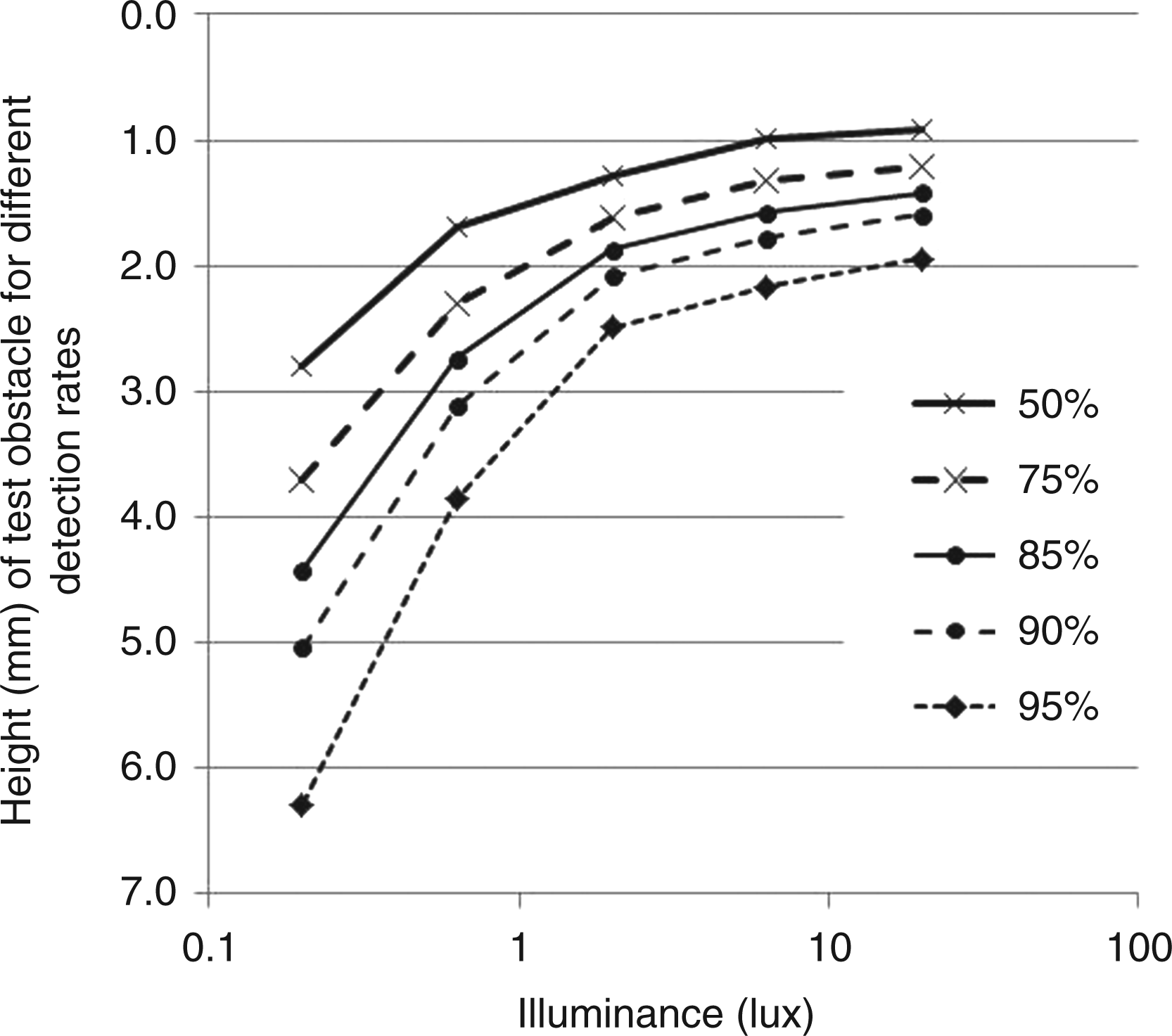
3. The legal approach
The first approach to identifying a minimum illuminance identifies a particular value because higher illuminances do not tend to provide useful return in terms of increased obstacle detection. This might be considered the visual performance approach. An alternative approach is to ask what size of obstacle is lighting expected to reveal and what probability of detection should be expected in order for a local authority to demonstrate it is meeting its obligations, and this might be considered a legal approach.
3.1. Critical obstacle size
The first question relates to the size of the obstacle, for example the height by which a paving slab is raised. There is some evidence of this from local authorities and solicitors in the UK, the former seeking to promote public safety by repairing potential hazards in a cost-effective way and the latter identifying opportunities as to when a trip may be deemed the fault of the local authority and thus liable for a compensation payment.
Local authorities in the UK are responsible for making sure pavements are free from trip hazards and other defects to ensure public safety. 24 Many local authorities use a height of 25 mm as an informal maintenance standard for pavement obstacles or defects – the height that triggers work to reduce or remove the defect. However, when it comes to court judgements relating to injuries from uneven paving, it is not only the height of a pavement defect that is considered but also how foreseeable the trip hazard is ‘in the eyes of a reasonable person’. 25
Where individual local authorities in the UK define a pavement defect by size (depth or height), this tends to be in the region of 15 to 25 mm to be a potential hazard and is thus prioritised for repair; If a defect is more than 20 mm deep it will be considered hazardous and our inspector will mark it with yellow paint. Defects that are less than 20 mm deep wouldn’t normally be considered a hazard.
26
The Council regularly inspects its footways for defects where levels vary by 15 mm or more.
27
Hertsmere Borough Council
28
addresses trip hazards and other pavement defects in priority order:
Priority 1: Potholes with a trip exceeding 20 mm in a busy urban area and a depression greater than 25 mm deep and less than 600 mm in plan. Priority 2: Slab movement, uneven ironwork and potholes with a trip exceeding 20 mm in a lightly pedestrianised area, and major cracking on busy footway (but with gap width/depth less than 15 mm). Priority 3: Major cracking on less busy footway (but with gap width/depth less than 15 mm), defective trenching with level difference exceeding 10 mm, and tarmac disintegration with less than 20 mm difference in level on urban footways.
Solicitors in the UK have reported that the height of a trip hazard needs to be at least 25 mm above or below the surrounding pavement before it is considered dangerous and can be used to bring a claim. 29 This is not, however, a universal value, and a pavement irregularity of height less than 25 mm may also be considered to be a danger in some contexts giving consideration to location and typical user; for example, a stretch of uneven paving outside a factory probably would not be a danger for foot traffic but a similar stretch outside an old people's home that must be used by the residents to the knowledge of the highway authority might be. 30 The courts in Northern Ireland have generally accepted the 20 mm intervention level as the benchmark on an actionable defect. 30 In general, the greater the height of the trip hazard, the better the chance of a successful claim for compensation. 31
A critical obstacle size of 25 mm was therefore chosen for the current analysis. Note that this refers to the height of a real obstacle on the plane of the pavement and not the height of a simulated obstacle as used in the current experiment.
3.2. Detection distance
Visually meaningful consideration of the size of a target uses the visual arc subtended by the target at the observer’s eye, and definition of this requires an estimate of the distance at which a 25 mm obstacle should be detected. One way to estimate detection distance would be to consider the typical forward distance at which pedestrians scan the road.
There is some evidence that at photopic levels foveal fixation for known stepping locations is about two paces ahead, the distance test participants tend to look when required to step over an obstacle in their travel path.32,33 However, an eye-tracking study of natural locomotion in a room full of obstacles demonstrated that visual fixation of obstacles is not required for rapid and adaptive navigation of obstacles; foveal vision plays a surprisingly minor role in visual guidance of locomotion under normal viewing conditions. 22
A tendency to fixate two steps ahead when required to navigate an obstacle suggests a need to detect an obstacle beyond this distance. Since such detection distance is unknown and likely to be random, a range of distances were considered, thus giving a range of sizes of target obstacles. It was therefore decided to examine detection of a 25-mm high obstacle when placed at forward distances of two, four, six, eight and ten paces.
The typical step length of older people is just under 600 mm. 34 For younger people it may be longer than this, and thus a typical step length of 600 mm was assumed. For a reference eye height of 1500 mm, the 25-mm high obstacle would present a visual size of 13.5 minutes to 28.2 minutes for ten paces to two paces ahead.
3.3. Detection probability
No data were found to guide the expected detection probability. Therefore, detection probabilities of 50%, 75%, 85%, 90% and 95% were assumed in order to explore the resultant variation in illuminance. Figure 7 shows how the relationship between obstacle size and illuminance varies with detection probability as determined from the current results. Essentially, these are the data points from Figure 6 redrawn with the ordinate scaled in terms of angular height subtended at the observer’s eye instead of vertical height in mm. To enable extrapolation, the curves in Figure 7 were determined using a three-parameter exponential decay model fitted by minimising the root mean square error:
Obstacle detection results plotted against visual size (minutes of arc). The curves were drawn using a three-parameter exponential decay model
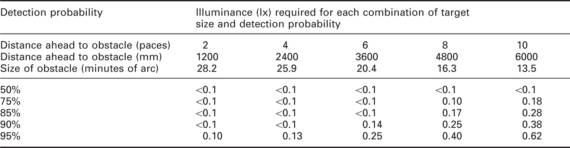
Illuminance (lx) required for a young person to detect an obstacle under high pressure sodium (HPS) lighting in a uniform field for combinations of target size and detection probability
4. Conclusion
The aim of this paper was to explore two approaches by which the detection of pavement obstacles might be used as a criterion with which to establish appropriate light levels for pedestrians. In doing so, the paper also provided validation of the results of a previous study of obstacle detection.
The first approach sought to identify the point of diminishing returns in the curve of obstacle detection versus illuminance, and for a 95% probability of detection this is approximately 2.0 lx. The second approach sought to identify expectations of the end user, which in this case is the local authority providing the lighting which needs to be able to show that it has taken reasonable steps to protect against trip hazards. For an obstacle of height 25 mm at a distance of 6 m, subtending a visual arc of 13.5 minutes, an illuminance of 0.62 lx is required for a 95% probability of detection by young people under HPS lighting.
These illuminances were found using test apparatus with a surface reflectance of r = 0.20. The standard assumption for a road surface is that the reflectance is 0.07 (although this may be erroneous 35 ), in which case the laboratory illuminances of 2.0 lx and 0.62 lx represent road surface illuminances of 5.7 lx and 1.8 lx, respectively.
Given these the two estimates, the higher (5.7 lx) would be put forward as the recommended minimum in design guidance, as Figure 6 suggests a rapid reduction in obstacle detection for lower illuminances. These estimates are at the lower end of the range of minimum average illuminances recommended in BS EN 13201-2. 1 Illuminance recommendations are not determined by visual needs alone but are subject to practical, financial and emotional forces. 36 These forces are dynamic: At present in the UK there is a growing trend to switch off road lighting at certain times as an energy saving measure, 37 so it is useful to understand what lighting is needed to contribute to this balance.
The thresholds reported in this paper are not intended to be considered for application in real situations. The current results were obtained by a laboratory experiment with one type of lamp (HPS), using young observers and a static, non-complex visual scene. Further data are needed for a wider range of lamps, for older subjects, and to approach the visual experience of pedestrians in real situations, i.e. continuous observation of a dynamic and more complex field, and to consider also the effects of the spatial distribution of light. Results from previous work 19 suggest that significance of the effects of age and SPD may vary depending on the approach used to estimate the appropriate illuminance. If this is to be set by definition of a standard obstacle and expected detection rate, described above as the legal approach, this would fall within the escarpment region of Figure 1 which shows that for the same level of obstacle detection, older people require a higher illuminance than do younger people, and lighting of higher S/P ratio, such as metal halide lamps, requires a lower illuminance than lighting of lower S/P ratio, such as HPS lamps. However, if the transition point in the plateau-escarpment curve of detection versus illuminance is used to define the required illuminance, then Figure 1 suggests that effects of age and SPD may not be significant.
Finally, we would remind the reader that this is not a proposal to base illuminance recommendations solely on the needs of obstacle detection but to explore the means by which the needs of obstacle detection can provide an estimate of an appropriate illuminance. Other visual tasks for pedestrians include recognition of the intent and identity of other pedestrians and judgements of perceived safety and the illuminance provided must meet the needs of these tasks in addition to meeting practical, financial and emotional forces. 36
Footnotes
Funding
This work was carried out through funding received from the Engineering and Physical Sciences Research Council (EPSRC) grant number EP/H050817.