
Abstract
Additive manufacturing enables the integration of functionalities during the production process. The effective structural health monitoring (SHM) system relies on the integration of small capillaries inside the structure, of which the pressure is monitored during the operation of the component. The pressure monitoring system allows deriving the loading condition of the part and detects upcoming fatigue failures, thereby creating smart, self-sensing objects. Such technology is of immediate benefit to structurally loaded parts that otherwise require significant inspection and maintenance efforts. Especially those parts, however, have to meet stringent quality standards. The inclusion of such intrusive capillary network, along with the use of a novel manufacturing technique, imposes significant materials and component testing in order to substantiate the added value of such system to metal additively manufactured parts. The current work therefore presents quasi-static materials testing, coupon fatigue testing and component fatigue testing with an embedded SHM system. The (post-) processing conditions of the fabricated parts were varied in order to understand their impact on the mechanical behaviour while attempting to reduce the structural impact of the embedded channels of the effective SHM system.
Introduction
Additive manufacturing (AM) is a group of manufacturing processes that build an object layer-by-layer from a computer-aided-design model. Powder bed fusion (PBF) – recognized as one of the most commonly known and adopted AM technologies1– relies on a heat source (typically laser, hence denoted as PBF-LB) to selectively fuse together a pre-deposited layer of loose atomized particles. Such additive processes allow the manufacturing of lightweight components through complex designs, while enabling the integration of functions inside the component. When compared to traditionally manufactured products, parts produced by PBF yield up to 25% higher strength, but the presence of larger tensile residual stress, surface roughness and porosity, result in lower fatigue strength and life. 2 Annealing, hot isostatic pressing (HIP), stress relief (SR) and additional surface finishing operations improve the characteristics of parts produced by AM. 2 Especially those components operating in highly stressed and cyclically loaded conditions, benefit from these post-processes to avoid fatigue initiation and rupture.
According to the ARP6461 standard, structural health monitoring (SHM) is defined as the process of acquiring and analysing data from on-board sensors to evaluate the health of a structure. Such systems are capable to continuously monitor the presence of structural damage throughout a component’s operational lifetime. The effective SHM (eSHM) system is one example of an SHM system that can be integrated during the AM process. Its core principle relies on the integration of a capillary during the AM process that is set to under- or overpressure, and subsequently sealed prior to the actual usage of the component. 3 The capillary pressure is then continuously monitored while in operation. The positioning of the capillary is made such that a propagating fatigue crack breaches through the embedded capillary, thereby inducing a leak flow towards the outer atmosphere. A pressure sensor picks up the pressure changes inside the capillary, thus enabling the detection of a fatigue crack. The operational principle is graphically presented in Figure 1.
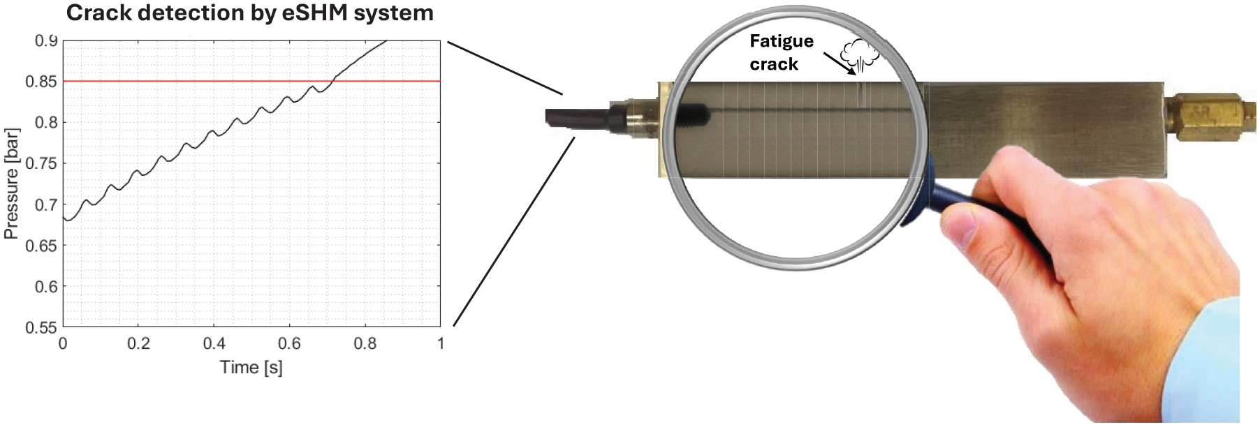
A graphical representation of the eSHM system’s operational principle. eSHM: effective structural health monitoring.
The eSHM system has been widely studied in the past and proven to be able to detect fatigue cracks.4–6 Hinderdael et al. 6 reported the issue of premature fatigue initiation as a result of the surface roughness of an integrated capillary for SHM purposes in highly, dynamically loaded Ti-6Al-4V parts. Jardon et al. 7 investigated a hybrid additive-subtractive approach for eSHM integration through the use of milling operations for the capillary channel. The use of a chemical etching (CE) post-treatment has shown to reduce the capillary surface roughness, avoiding premature fatigue failure. 8 Further investigation on the influence of (post-)processing conditions on the capillary roughness, fatigue resistance and eSHM system performance is needed. The current work therefore explores the effect of various layer thicknesses (30 and 60 µm) and different post-processes (SR, HIP and CE) on the surface roughness, quasi-static and dynamic material properties of Ti-6Al-4V coupons processed by PBF-LB, while evaluating the eSHM system performance.
The effect of post-treatments, including heat treatments, HIP and surface treatments, on the quasi-static and dynamic material behaviour of PBF-LB processed Ti-6Al-4V has been an important research subject in the past, reaching comparable or even superior tensile, fatigue, fracture toughness and creep properties than those of cast and/or wrought Ti-6Al-4V. 9 Li et al. 10 concluded in their review work that various AM (including PBF-LB) techniques can produce samples with superior fatigue performance over wrought and annealed Ti-6Al-4V, but no AM process achieved them without post-processing treatments. The three most researched post-processes mitigate the process-induced residual stress (through heat treatments), internal defects (through HIP) and surface roughness (e.g. through machining, CE).
When considering quasi-static material properties, as-built bulk PBF-LB’ed material presents a higher ultimate tensile strength (UTS) and yield strength (YS), but lower ductility than their wrought counterpart.9,11–14 This finding has been attributed to the high cooling rates involved in the PBF-LB process, introducing a fine martensitic acicular
The high cycle fatigue (HCF) behaviour of PBF-LB processed Ti-6Al-4V is predominantly dictated by the residual stress, densification level, the microstructural features and the surface condition.1,20,25 While annealing14,26,27 and machining14,26 significantly improved the fatigue life under all loading conditions, the overall improvement did not reach the levels as expected from wrought samples due to remnants of internal or near surface defects. 14 A HIP treatment further improves the HCF behaviour, reaching levels comparable to wrought specimens.19,26 The HIP process is believed to compress internal defects into small high-pressured pores with sizes below the resolution of X-ray tomography,28–30 minimizing their structural impact. A HIP process becomes less effective as the residual porosity in as-built conditions reach very low values. 27 The work of Cutolo et al. 27 deployed the same ProX DMP 320 (3D Systems, Rock Hill, South Carolina, USA) machine as used in this work, delivering residual porosity values as low as 0.6%.
Surface defects are the main driver for fatigue initiation under the as-built surface condition. 27 Many works have therefore investigated the beneficial effect of surface post-processing on the HCF of Ti-6Al-4V processed by PBF-LB. Most works reported on surface modification techniques that require physical access, including machining,31–33 blasting.31,33–37 vibratory grinding,31,35 micro machining process, 31 chemically accelerated vibratory polishing process 38 and laser shock peening.35,36 Their use is limited to outer, reachable surfaces, preventing their application to complex-shaped components and internal features. Other works have investigated surface treatment procedures that lead to surface roughness reductions of truss structures39,40,41 and integrated (cooling) channels, 42 through the use of CE37,39,40,43–45 and electrochemical polishing (EP).34,37,39,46 All works reported improved fatigue performance after CE41,43–45 and EP,34,46 preferably combined with a HIP treatment to further increase fatigue lifetime.41,45,47 The integration of a channel feature inside a component, as required for the eSHM system under investigation, results in a lower fatigue lifetime than solid specimens, with crack initiation mostly originating from the rough internal channel surface or process-induced porosity near the surface.42,47
The beneficial effect on the fatigue lifetime of a CE-treatment to PBF-LB processed Ti-6Al-4V surfaces has been shown on outer surfaces37,43–45 and internal truss structures.39–41,43 To the authors’ knowledge, although reported critical, 47 no works have explored the effect of CE on the fatigue lifetime of PBF-LB processed Ti-6Al-4V samples with integrated capillaries. Considering that the operational principle of the eSHM system relies on the integration of capillaries within the structure, and its purpose to detect fatigue cracks in dynamically loaded structures, a further investigation of the intrusive character of the capillary on the structural integrity of the part is indispensable. The current work therefore evaluates the influence of a SR, HIP and CE post-treatment on the quasi-static and dynamic properties of PBF-LB processed Ti-6Al-4V with integrated channels of the eSHM system.
Laser-manufactured Ti-6Al-4V and experimental methods
Sample manufacturing
In view of the dynamically loaded applications where the eSHM-system will be used to detect fatigue failures, the current work aims at reducing the surface roughness of the embedded capillary in order to prevent premature fatigue initiation. Therefore, samples were produced using different layer thicknesses and the use of several post-processes. Besides the actual evaluation of the surface condition, the effects of these varying (post-)process conditions on the quasi-static, fatigue and eSHM system performance are included in this discussion. These material properties were investigated on the basis of the sample designs as depicted in Figure 2 with the focus on Ti-6Al-4V coupons produced by means of PBF-LB.
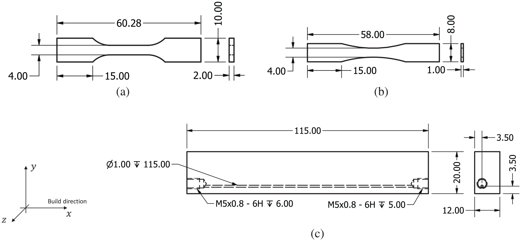
Designs of the (a) quasi-static tensile sub-coupon, (b) tensile fatigue sub-coupon and (c) four-point bending fatigue coupon with the capillary of the embedded SHM system (unit: mm). SHM: structural health monitoring.
All samples were manufactured by 3D systems on a ProX DMP 320 machine, equipped with a 500W fiber laser, using the standard process parameters for the LaserForm TiGrade 23(A) powder. Samples were built vertically using layer thicknesses either being 30 or 60 µm. The build chamber was flushed with Argon to create an inert atmosphere with an oxygen level below 25 ppm. The samples were built on top of a solid titanium build plate from which they were subsequently removed using wire electrical discharge machining. After this, all samples received a standard shot peening operation and were ultrasonically cleaned using de-mineralized water to remove unmolten powder particles.
Several batches were then separated, each of them receiving a different post-treatment. A first batch of samples was SR by heating the samples to 850°C for 2 h followed by air cooling. A second and third batch were subjected to a HIP process at a temperature of 920°C and a pressure of 1000 bar for 2 h. The third batch had furthermore undergone an additional CE process, called SILC cleaning (by 3D systems). SILC cleaning is a proprietary multi-step chemical cleaning process through flushing with an Hydrogen fluoride (HF)5-based solution (0.5 ml
Sample overview.
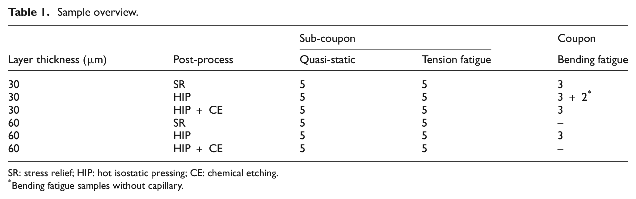
SR: stress relief; HIP: hot isostatic pressing; CE: chemical etching.
Bending fatigue samples without capillary.
Sample density
The density (and thus porosity degree) of the samples was determined based on an Archimedes test using the Kern YDB-01 density kit combined with the Kern EMB 200-3V balance with a 1 mg precision and 200 g range. The four-point bending coupon samples were ultrasonically cleaned while being submerged in ethanol and subsequently left to dry prior to the test. The relative density was calculated by comparison with the theoretical density of Ti-6Al-4V of 4429 kg/m3.
Surface roughness
The quasi-static sub-coupons as well as the tension fatigue sub-coupons were printed to final dimension (no finish milling), and received post-treatments as depicted in Table1 prior to testing. Their external surface roughness was measured using a Keyence VHX-6000 (Keyence, Osaka, Osaka, Japan) optical microscope. On the contrary, the outer surface of the four-point bending fatigue coupons was milled to final dimensions in order to shift the analysis to the impact of the inner capillary surface roughness of the embedded eSHM system on the fatigue performance of the coupons. After the fatigue test, the four-point bending fatigue samples were then cut halfway through the capillary by means of electron discharge machining. The visual access to the capillary walls allowed recording images by means of the Leica DMi8-A (Leica, Wetzlar, Germany) optical microscope, which exhibits the option of extending the depth of field by reconstructing the image based on multiple images taken at different heights. Both the outer surface roughness and the capillary surface roughness were quantified by means of the Mahr MarSurf (Mahr Group, Göttingen, Germany) PS10 using a 4.8 mm traverse length (
Quasi-static tensile test procedure
The quasi-static tension test was conducted using an ElectroPuls E10000 (Instron, Norwood, Massachusetts, USA) with a loading capacity of 10 kN at a displacement rate of 1 mm/min. While the applied load was directly recorded by the load cell during the test, the deformation of the specimen was measured using an extensometer with a gauge length of 5 mm attached to the surface of the specimens. In order to ensure the repeatability of the obtained mechanical properties, each testing case was repeated five times.
Dynamic fatigue test procedures
The tensile fatigue tests were conducted using the same test machine used for the quasi-static tests. The stop definition for these fatigue tests was based on the actual coupon failure leading to actuator displacements beyond pre-set limits. The four-point bending fatigue tests were conducted on a hydraulic test bench using a 200 kN dynamically rated MTS (MTS Systems Corp, Eden Prairie, Minnesota, USA) actuator. The load level, actuator displacement and eSHM system pressure were all recorded. Actuator displacement exceeding pre-set limits was used as the stop definition for the benchmark coupons without capillary of the eSHM system. The stop definition for coupons with embedded capillaries was additionally supported by the eSHM system output. The capillaries were initially pressurized to 0.1–0.2 bar absolute pressure, and a pressure limit at 0.85 bar was set to stop the fatigue test. As such, the eSHM system was challenged to detect fatigue cracks prior to structural failure. The samples were oriented such that the capillary was located on the tension side of the coupon in the four-point bending test setup (see also Figure 3).
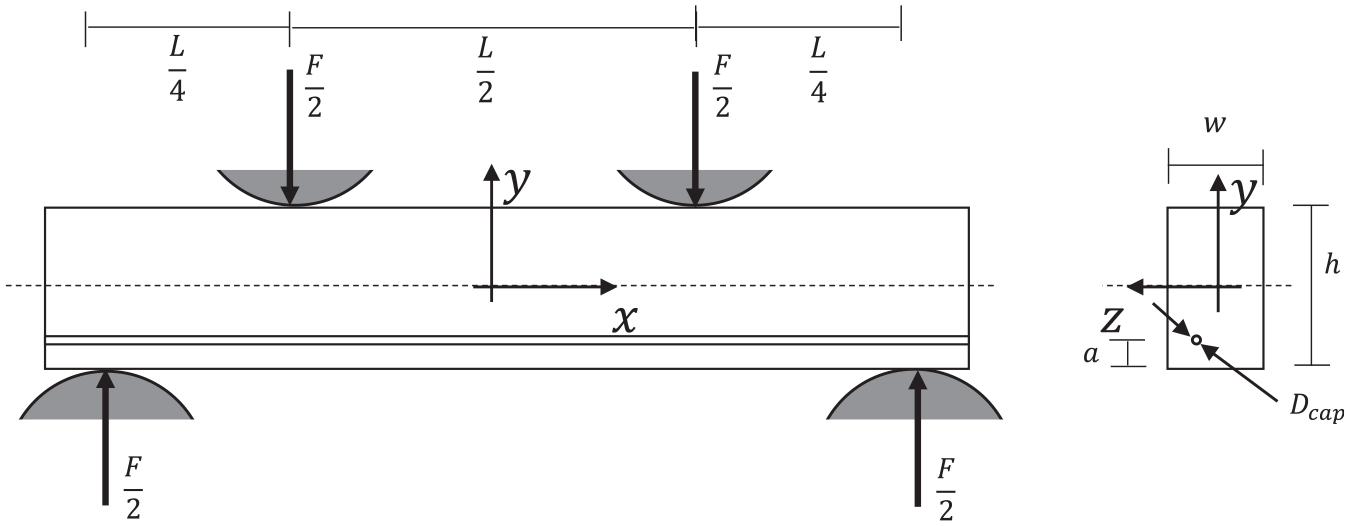
Four-point bending test setup configuration.
Both the uni-axially tension sub-coupons and the four-point bending coupons were subjected to the same step method, an accelerated fatigue test procedure allowing to save testing time and reduce the number of costly coupons to be tested. The fatigue tests were conducted at a test frequency of 15 Hz and a stress ratio (R) of 0.1. All coupons were initially loaded at a maximum stress level of 200 MPa (
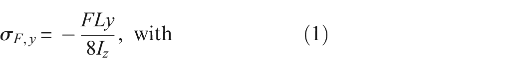
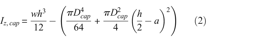
The following values were used for the calculus:
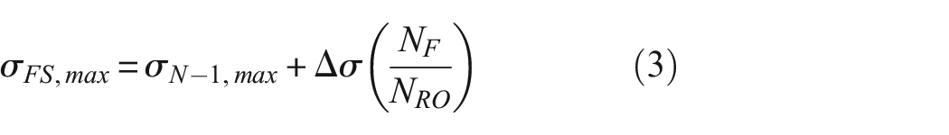
in which
While stress levels are constant across the test section in a uni-axial tensile fatigue test, stresses vary across the cross-section of a four-point bending coupon. Throughout the manuscript, the stress levels in a four-point bending configuration were either reported as present on the outer surface (
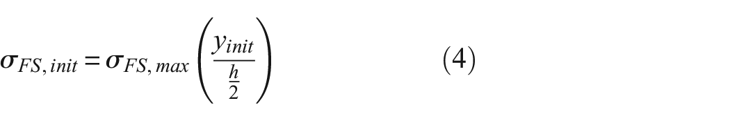
The initiation location, and more specifically, its vertical position on the cross-section (
Fractographic analysis
The fracture surface of the fatigue loaded samples was inspected by means of Scanning Electron Microscope (SEM) imaging on the JEOL JSM-IT300 (Jeol, Tokyo, Japan) to locate the fatigue initiation zone and to determine the cause of fatigue initiation.
Vickers hardness
Vickers hardness measurements were conducted on the four-point bending fatigue test coupons, by means of a Struers Duramin (Struers, Ballerup, Denmark) apparatus. Prior to the hardness test, the samples were polished using successively finer grid sizes and ending with a final wet polishing using P4000 sand paper. The samples were then subjected to the HV 0.2 test procedure with a test force of 1.961 N. The hardness of each sample was measured six times. The average (avg.) hardness and standard deviation (SD) across a single specimen configuration are reported.
Results
Relative density
The avg. relative density within each batch is reported in Table 2. All samples had relative densities above 99.6% with very similar sample densities for both samples that either did or did not receive a HIP post-process. This finding is in agreement with earlier density tests on the same material, processed by the same supplier, that were reported by Cutolo et al. 27
Density and surface roughness of external machined surface and as-built capillary surface of Ti-6Al-4V four-point bending fatigue coupons produced using different layer thicknesses and various post-processes (avg. ± SD).
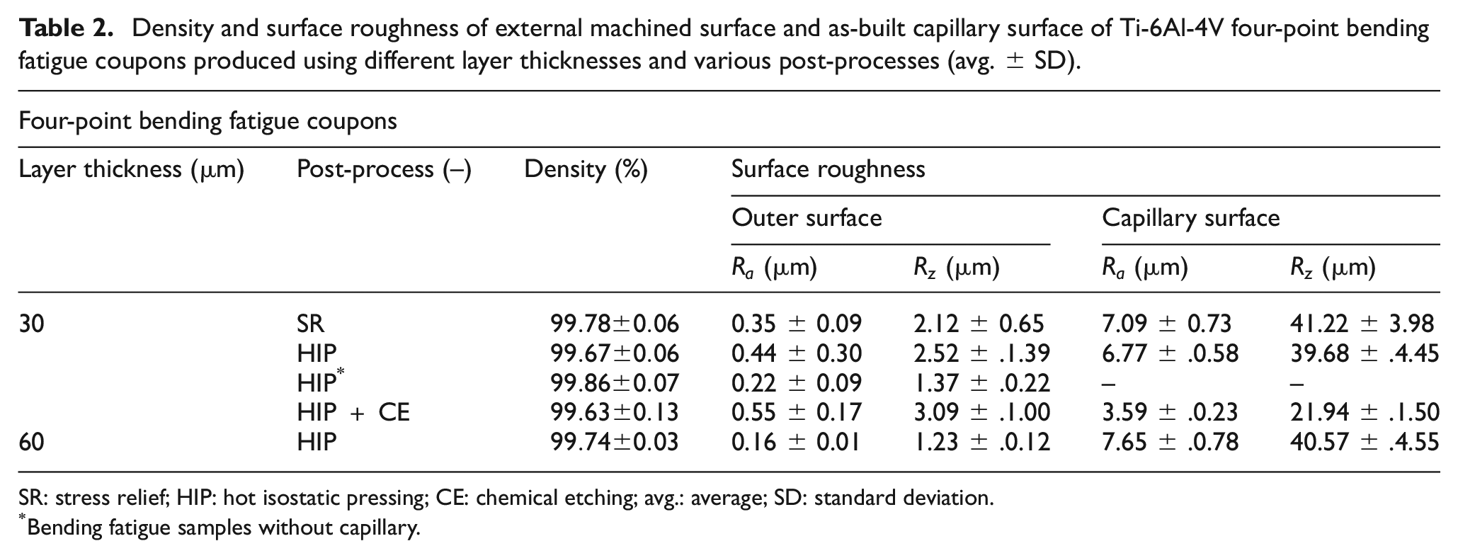
SR: stress relief; HIP: hot isostatic pressing; CE: chemical etching; avg.: average; SD: standard deviation.
Bending fatigue samples without capillary.
Surface roughness
The results of the surface roughness measurements are summarized in Tables 2 and 3. The outer surface of the four-point bending fatigue samples was finish milled, which clearly led to a reduced surface roughness (
Surface roughness of the Ti-6Al-4V tensile fatigue sub-coupons produced using different layer thicknesses and various post-processes, including common sand blasting (avg. ± SD).
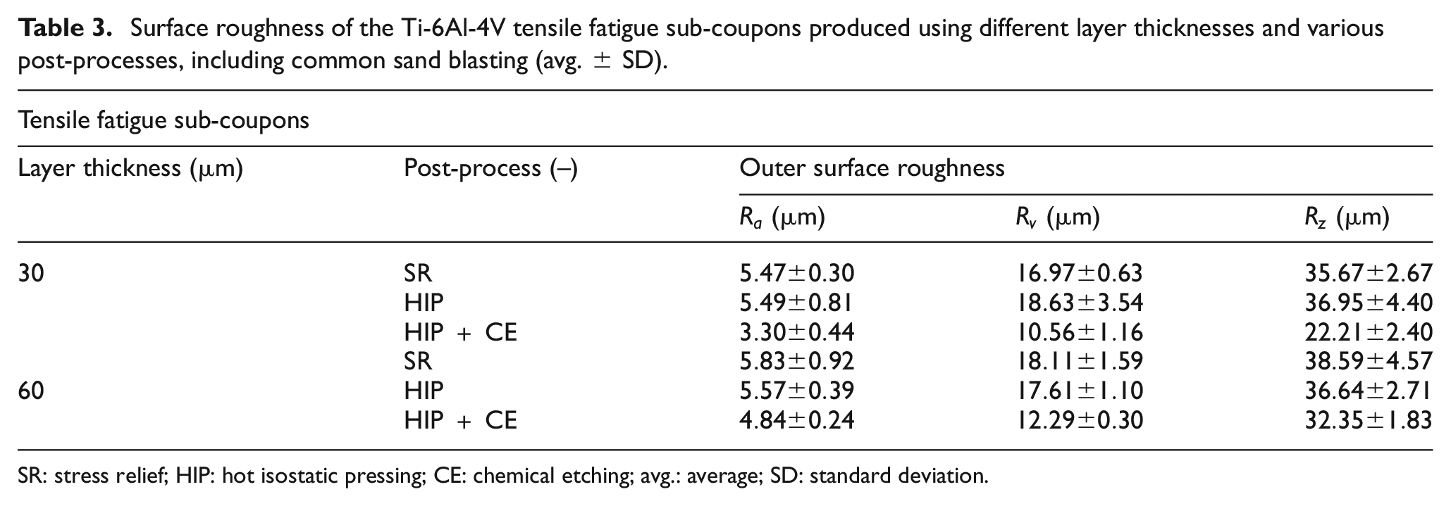
SR: stress relief; HIP: hot isostatic pressing; CE: chemical etching; avg.: average; SD: standard deviation.
Figure 4 presents the roughness profile as measured on the surface of the embedded capillary, and Figure 5 presents optical images on the capillary surface for the different processing conditions. The capillary surface state is very similar between the samples that were built using a 30 µm layer thickness and received either a SR or HIP post-process. The capillary roughness is composed of partly molten powder particles superimposed on solidified welding beats corresponding to the deposition process.
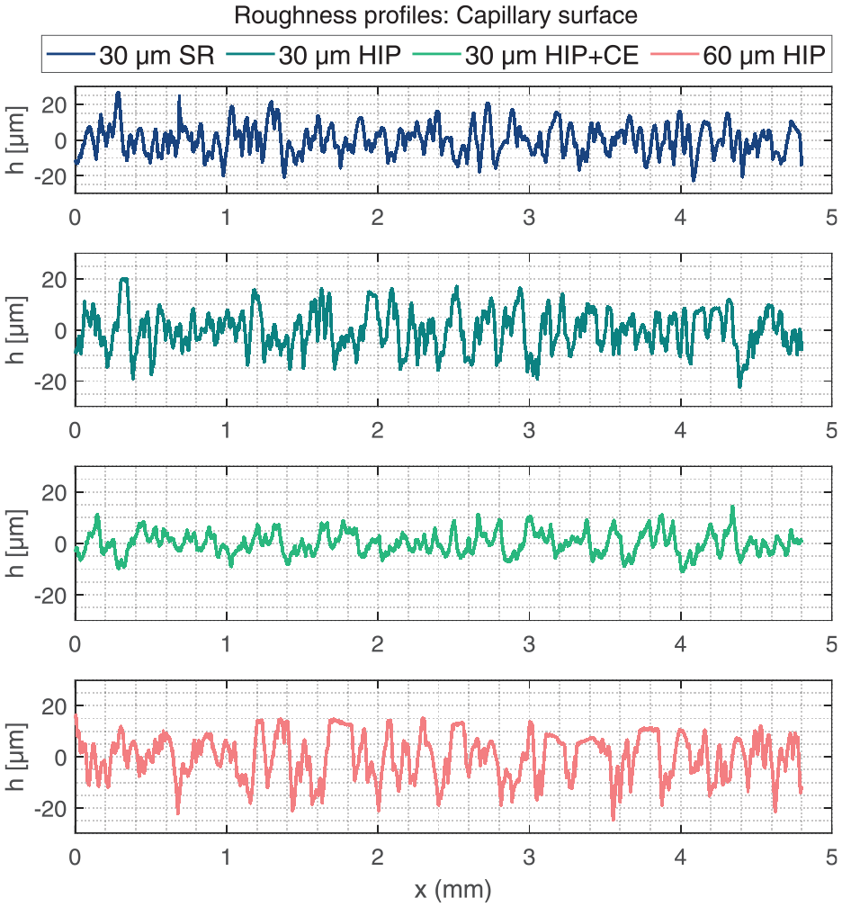
Surface roughness profiles of the inner surface of the capillary for the conditions: 30 µm SR, 30 µm HIP, 30 µm HIP + CE and 60 µm HIP. SR: stress relief; HIP: hot isostatic pressing; CE: chemical etching.
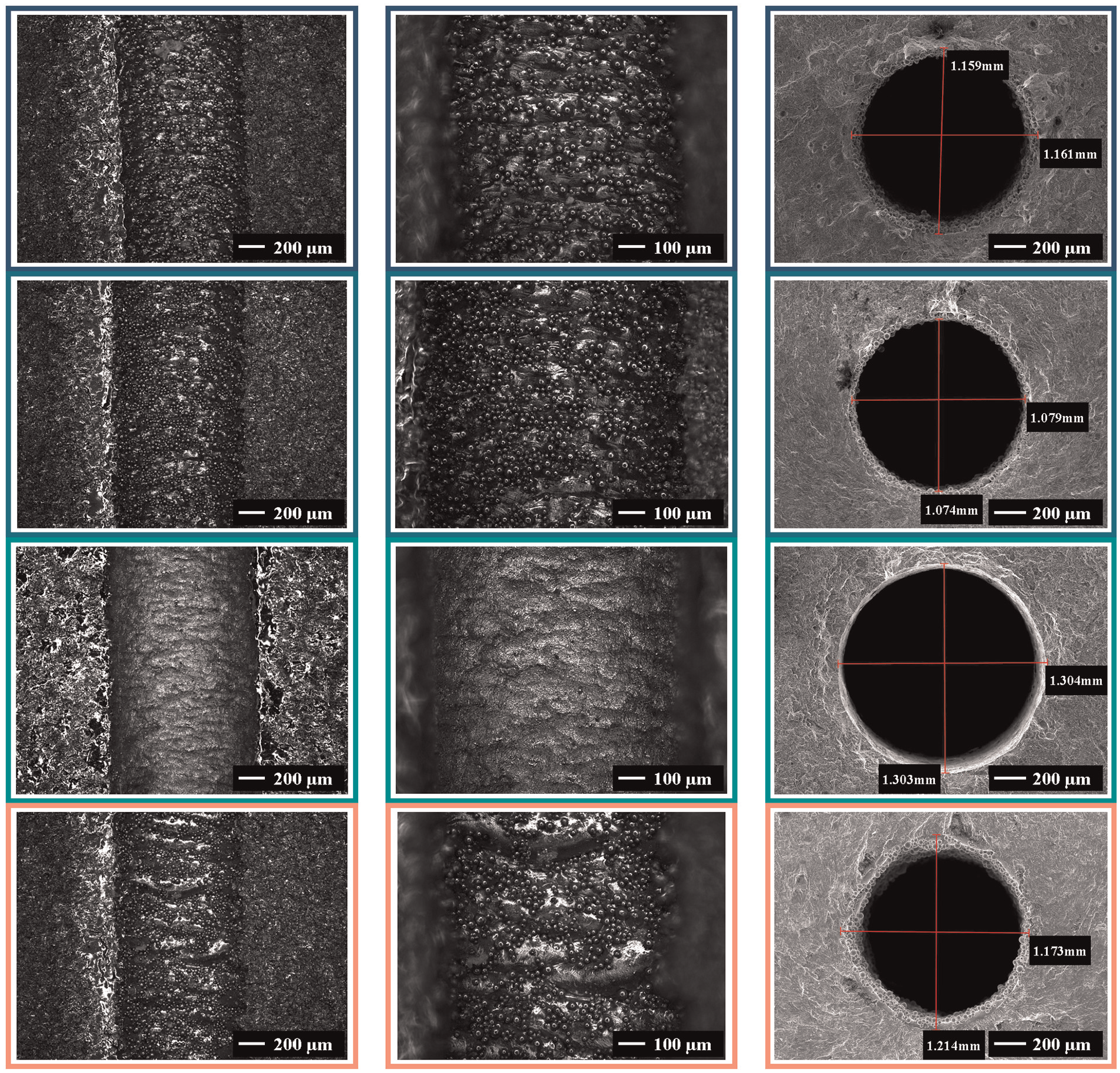
Optical (l,c) and scanning electron micrographs (r) of the embedded capillary. From top to bottom: 30 µm SR, 30 µm HIP, 30 µm HIP + CE and 60 µm HIP conditions. SR: stress relief; HIP: hot isostatic pressing; CE: chemical etching.
The additional CE post-treatment clearly resulted in a reduced capillary surface roughness. The CE procedure removed all partly unmolten powder particles and leaving behind only some minor traces of the layer-wise solidification of the deposition process. The capillary surface roughness state of the coupons produced using a 60 µm layer thickness corresponds well to those produced by means of a 30 µm layer thickness. The surface roughness profile of the 60 µm HIP coupons presents plateaus at the high regions, which, by deduction from the optical images, seem to correspond to the more apparent welding beats of the individual layers. Unmolten powder particles stick to the capillary surface.
Dimensions
The CE post-process is expected to remove material and alter the geometrical dimensions of the specimens. While the total thickness of the tensile fatigue coupons was reduced from 2.08 to 1.97 mm, a similar trend was observed on the capillary diameter. In specimens that did not receive a CE post-treatment, the avg. capillary diameter was found to be 1.10 mm in diameter, while after CE post-treatment, the avg. capillary diameter had enlarged to 1.22 mm. The CE post-treatment may therefore be assumed to be as effective on the inner capillary surface (60 µm material removal on either side) as on the outer surface (55 µm material removal on either side).
Vickers hardness and quasi-static tensile test
The test results of the Vickers hardness and quasi-static tensile tests are summarized in Table 4 and visually presented in Figure 6. The sub-coupons produced with either 30 or 60 µm presented very comparable test results, and the following discussion applies to both cases. The HIP post-treatment resulted in a lower hardness, lower YS, lower UTS but increased ductility. The effects on the Young’s modulus remain small. The additional CE post-treatment resulted in a slightly higher hardness, but similar YS and UTS. Elongation at failure has been further increased by the CE post-treatment. Microstructural analysis reveals strong similarities between samples processed using the 30 and 60 µm layer thickness, but vastly distinct microstructures between the SR and HIP conditions. From Figure 7, a fine acicular martensitic microstructure can be seen in the SR conditions, while elongated
Vickers hardness and quasi-static tensile test results for Ti-6Al-4V coupons produced using different post-processes and layer thicknesses (avg. ± SD).
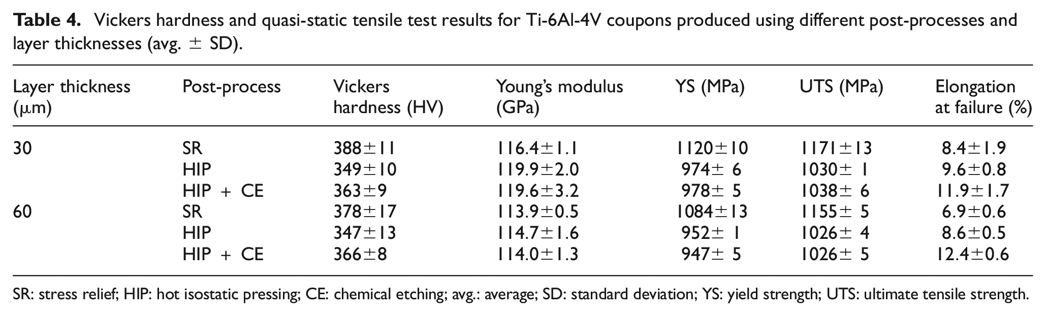
SR: stress relief; HIP: hot isostatic pressing; CE: chemical etching; avg.: average; SD: standard deviation; YS: yield strength; UTS: ultimate tensile strength.
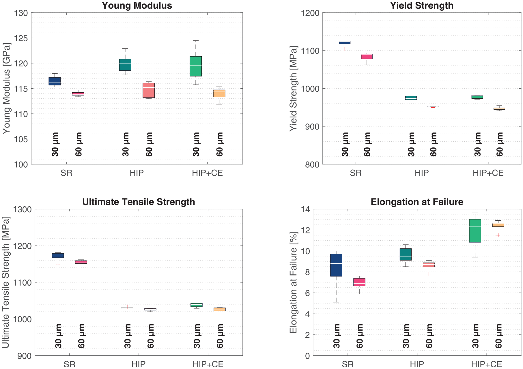
Quasi-static tensile results of Ti-6Al-4V coupons produced using different post-processes and layer thicknesses.
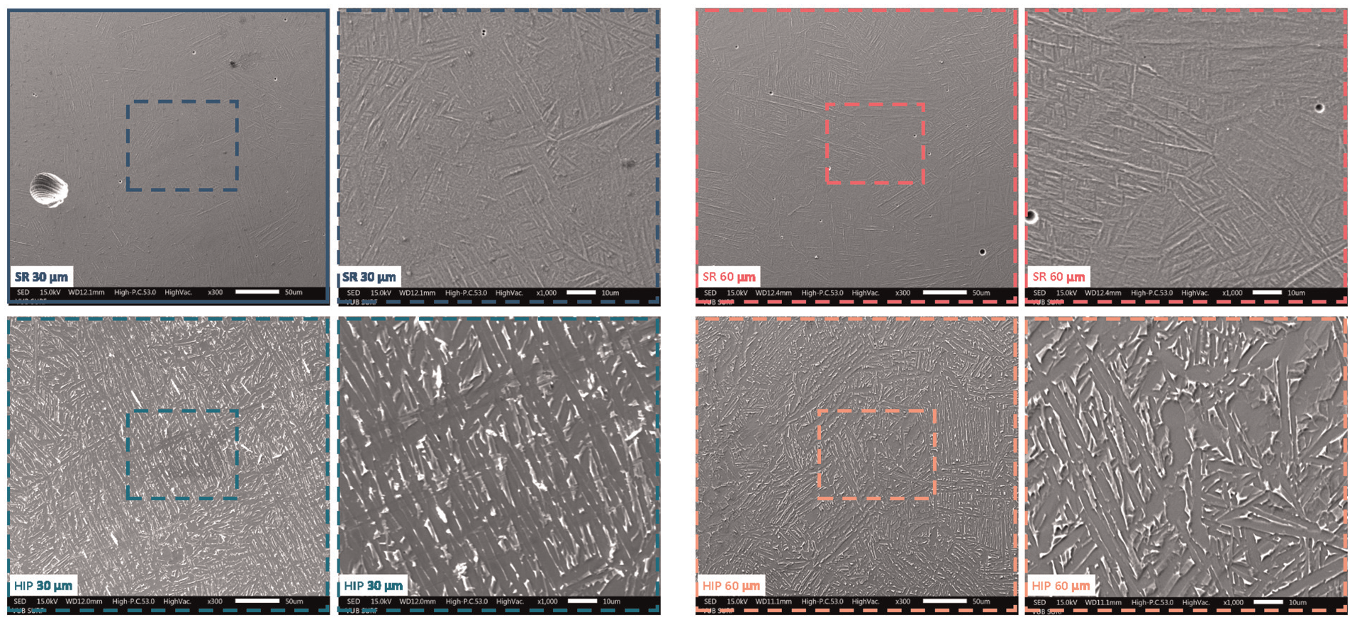
Scanning electron micrographs of polished and etched surfaces, for microstructural analysis (top: SR – bottom: HIP. Left: 30 µm – right: 60 µm). The SR conditions present a fine acicular martensitic microstructure, while the HIP-processed samples reveal elongated
HCF and fracture analysis
Tensile fatigue. As presented in Table 1, tensile fatigue sub-coupons were manufactured using two different layer thicknesses of 30 and 60 µm and having received three different post-processes; SR, HIP and HIP + CE. For each configuration, five samples were manufactured and subjected to an accelerated tensile fatigue test. The fatigue strength of the samples was calculated by means of Equation (3). Table 5 presents the avg. and SD of the fatigue strengths obtained for the different configurations. Figure 8 presents a box-plot representation of the same data.
Summary of tensile fatigue test results of Ti-6Al-4V coupons produced using different layer thicknesses and having received a SR, HIP and CE post-treatments.
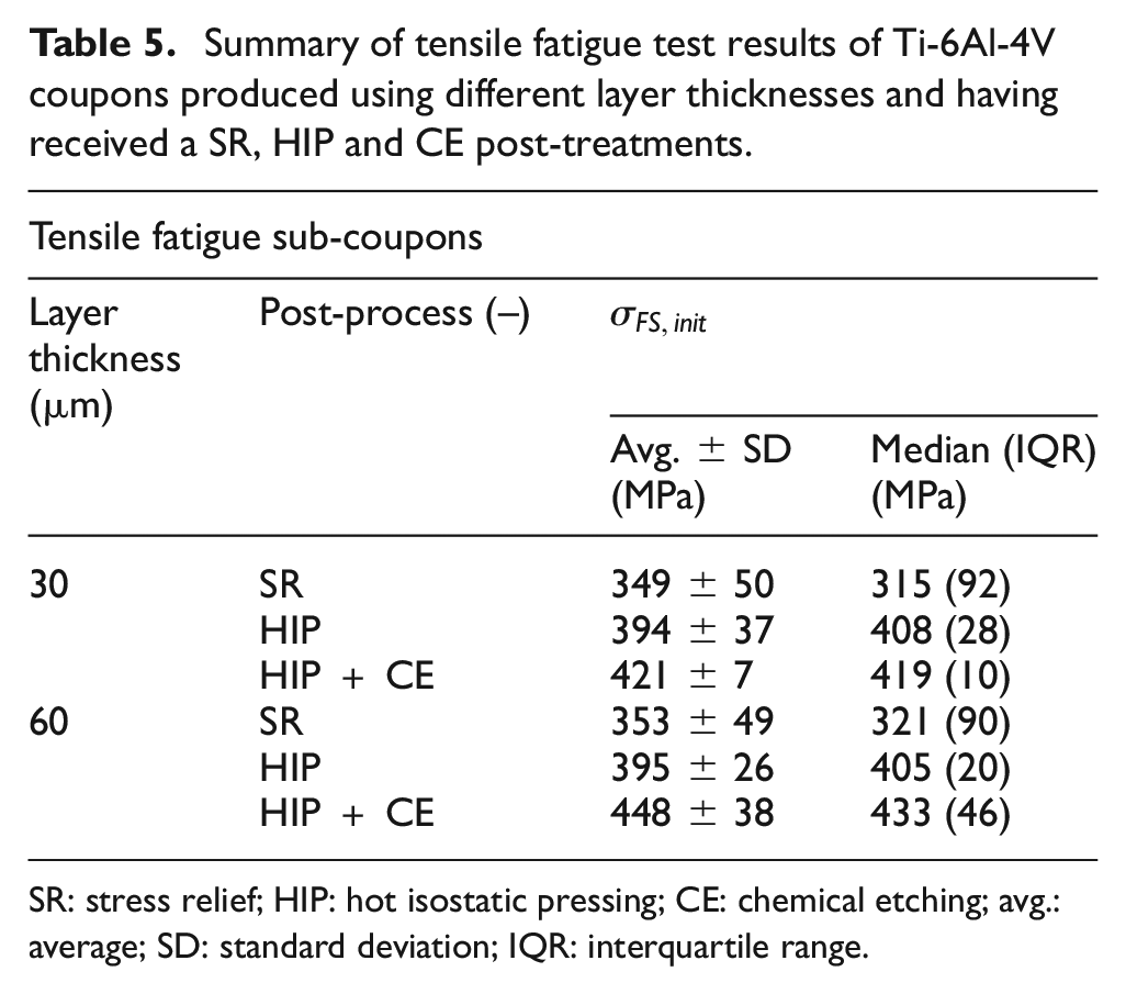
SR: stress relief; HIP: hot isostatic pressing; CE: chemical etching; avg.: average; SD: standard deviation; IQR: interquartile range.
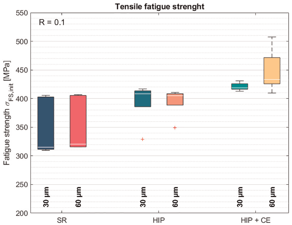
Box plot presentation of tensile fatigue test results of Ti-6Al-4V coupons produced using different layer thicknesses and having received a SR, HIP and CE post-treatments. SR: stress relief; HIP: hot isostatic pressing; CE: chemical etching.
The stress-relieved samples show the lowest avg. fatigue strength for both layer thicknesses (349 and 353 MPa) and present a significant spread on the fatigue strength with SDs around 50 MPa and interquartile range (IQR) around 90 MPa. Samples that were subjected to a HIP post-process presented a higher fatigue strength around 400 MPa and significantly lower spread on the fatigue results. One outlier was observed in each HIP configuration, skewing the avg. and increasing the SD. A further increase in the fatigue strength has been observed when the samples were subjected to an additional CE post-process. The avg. fatigue strength raised to 421 and 448 MPa, respectively, for the 30 and 60 µm condition. In clear contrast to the 30 µm samples which presented extremely consistent fatigue strengths (SD 7 MPa and IQR 10 MPa), a larger spread on the fatigue strengths was observed for the 60 µm samples (SD 38 MPa and IQR 46 MPa).
Figure 9 presents an overview of the fracture surface of one sample of each configuration. River marks are noticeable on the fracture surface, pointing towards the fatigue initiation sites. Figure 10 presents the fatigue initiation sites in more detail. According to these results, in all cases, the fatigue crack has initiated from the surface. In three occasions, the fatigue crack initiated from a corner, while in the three other cases signs are present of severe waviness due to melt pool behaviour. The residual surface roughness is most likely the cause of the fatigue initiation as no defects were found near the fatigue initiation sites. Figure 11 shows the residual porosity due to gas inclusions as observed on the fracture surface of the stress-relieved sample produced using 30 µm thick layers.
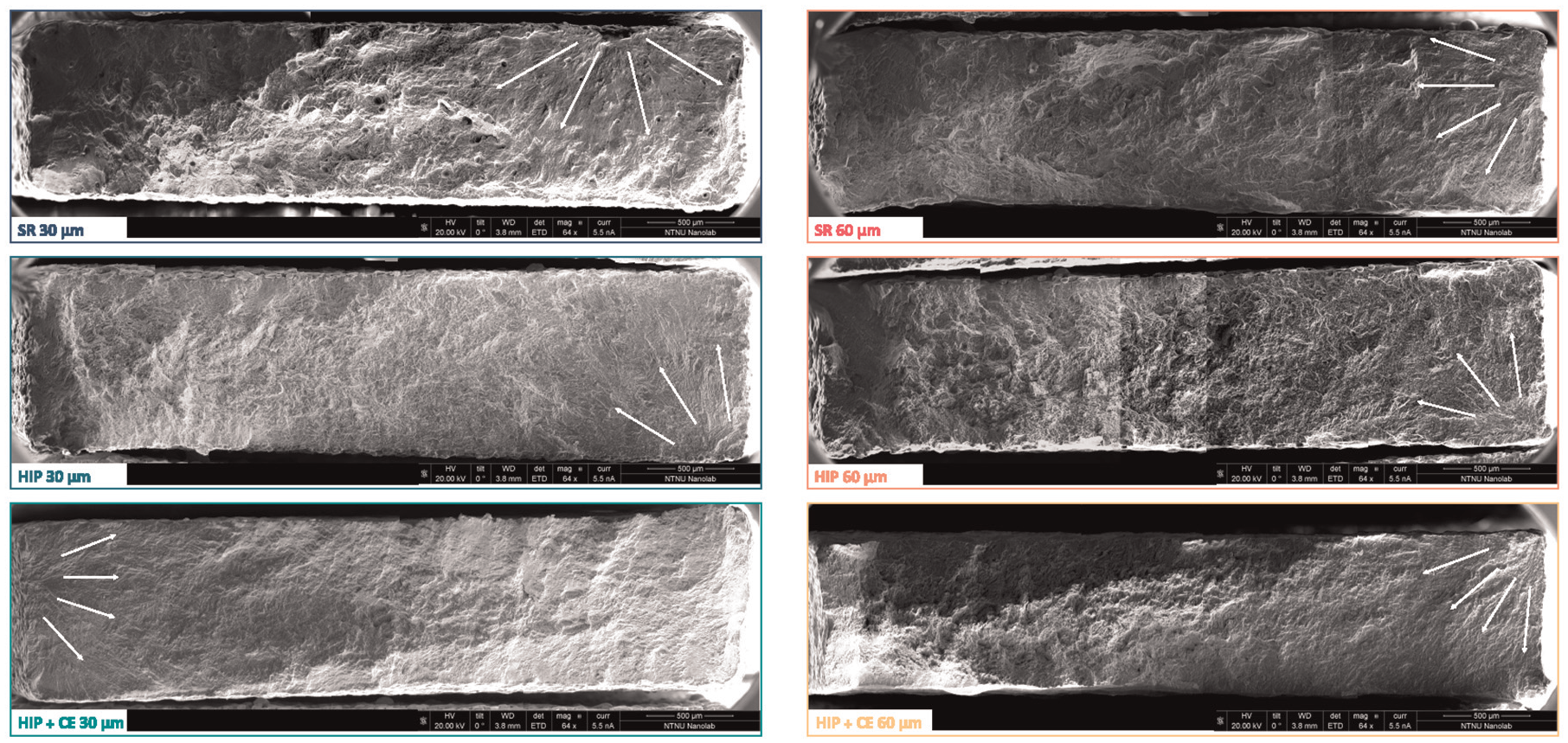
Fracture surface of the tensile test coupons.
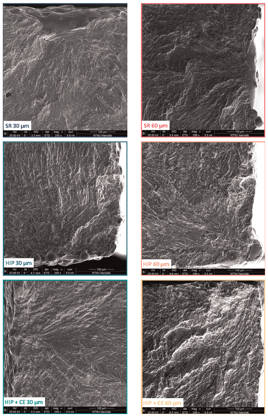
Fatigue initiation sites on the fracture surface of Ti-6Al-4V coupons processed using different layer thicknesses and post-processes.
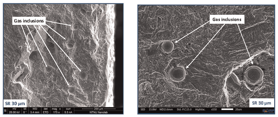
Fracture surface of the stress-relieved tensile test coupons, presenting residual porosity due to gas inclusions.
Four-point bending fatigue. Besides the material testing on sub-coupon level as presented previously, also coupons were subjected to fatigue testing. Rectangular beams – with or without the integrated eSHM system – were loaded in a four-point bending configuration (see Figure 3). Table 1 presents the number of samples tested in each configuration. Two benchmark coupons (30 µm HIP’ed) without integrated eSHM system served as reference for all other coupon tests with integrated eSHM system. Table 6 presents the fatigue test results, including the stresses at failure as expected to be present on the outer surface (
Four-point bending fatigue test data of Ti-6Al-4V coupons with/without embedded capillary of the eSHM system, produced by PBF-LB using different layer thickness and SR, HIP and CE post-treatments.
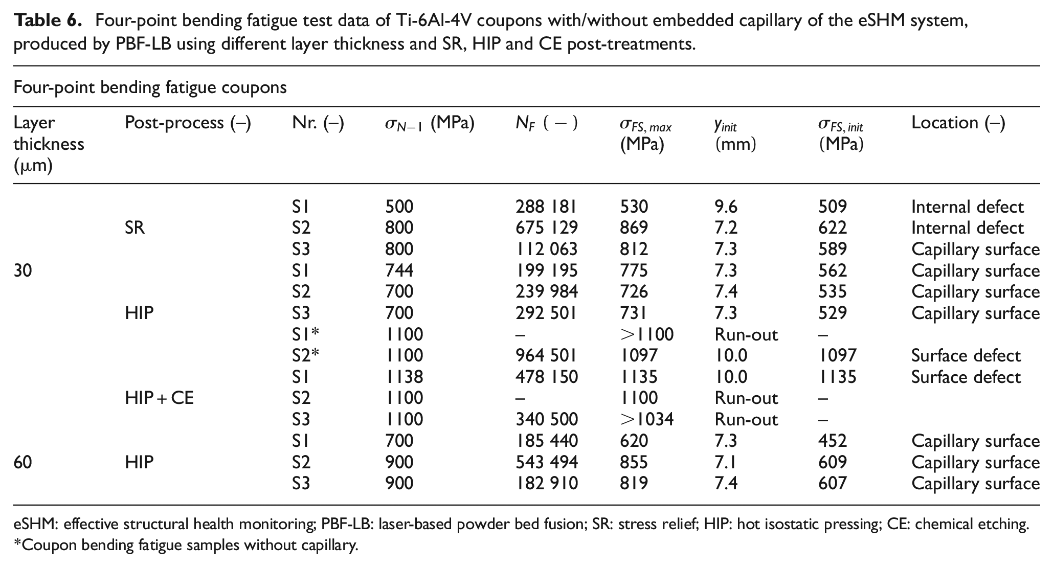
eSHM: effective structural health monitoring; PBF-LB: laser-based powder bed fusion; SR: stress relief; HIP: hot isostatic pressing; CE: chemical etching.
Coupon bending fatigue samples without capillary.
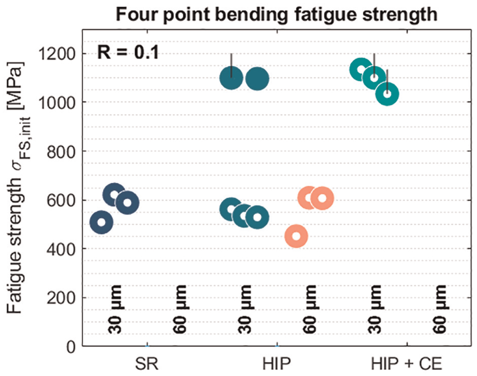
Four-point bending fatigue test data for coupons produced using different layer thicknesses and post processes: SR, HIP and HIP + CE. Solid data points represent coupons without capillary (benchmark) while hollow data points represent coupons with embedded capillary of the eSHM system. The data present the stresses as analytically calculated to be present at the initiation site (derived from fractographic analysis). eSHM: effective structural health monitoring; SR: stress relief; HIP: hot isostatic pressing; CE: chemical etching.
The first benchmark coupon S1* survived all fatigue loading including one million cycles at 1100 MPa and thereby reached the maximum test capacity of our setup. This test result is presented as a dot at the maximum tested stress level with a vertical line indicating run-out. The second benchmark coupon S2* failed at a fatigue strength of 1097 MPa. The inclusion of a capillary significantly affected the fatigue strength of the component, with failures occurring at respectively 562, 535 and 529 MPa for the coupons produced using a 30 µm layer thickness and having received a HIP treatment. Even more apparent is to notice that, besides those coupons that have undergone a CE treatment, all coupons across the different processing configurations equally performed in terms of fatigue strength. Only the coupons with embedded capillary that received an additional CE treatment (′30 µm HIP + CE′) outperformed all other coupon samples with integrated capillary. The fatigue strength of these coupons was, respectively, 1135, 1100 and 1034 MPa, but two main remarks have to be made here. Firstly, the single specimen that failed above 1100 MPa, was effectively loaded above the capacity of the test machine, leading to difficulties to retain the high load levels, test frequency and/or sinusoidal excitation. It was therefore concluded that samples outperforming one million cycles at 1100 MPa would be considered as run-out, rather than continue testing above the maximum capacity of the test bench and approach plastic deformation in some areas of the specimen (see also Table 4). Hence, a vertical line is placed on the plot showing the run-out condition of this specimen. Secondly, the test coupon that failed at 1034 MPa, initiated around the contact point with the rollers. It may therefore be concluded that the actual testing zone still survived the fatigue loading till that point. Therefore, also in this case, a black vertical line indicates that the actual fatigue strength of the material is higher than the reported one.
Fractographic analysis was used to determine the fatigue initiation cause. Figure 13 presents some overview images of the fracture surfaces of the four-point bending coupons. The most important fracture surface features are schematically presented in the top-left corner of the subfigures. The black dot represents the capillary of the eSHM system. The initiation location is indicated with a triangle, from where the fatigue crack front has emerged. Also, optical microscope observations were used to analyse the fracture surface. The presence of a beachmark caused by the sudden stop of the fatigue test bench, or slight oxidation of this specific area on the fracture surface reveals the crack front at crack detection by the eSHM system, which has been presented on the schematic overview as a dashed line. In all cases, the test was successfully stopped by the eSHM system prior to the final fracture of the coupon. Subsequently, the test was therefore relaunched at the same failure load level to quantify the remaining useful lifetime after detection by the eSHM system and to fail the specimen for the fractographic analysis. The solid line on the schematic representation then presents the position of the fatigue crack front at the final fracture, thereby indicating the barrier between gradual fatigue crack growth behaviour and the sudden final fracture.
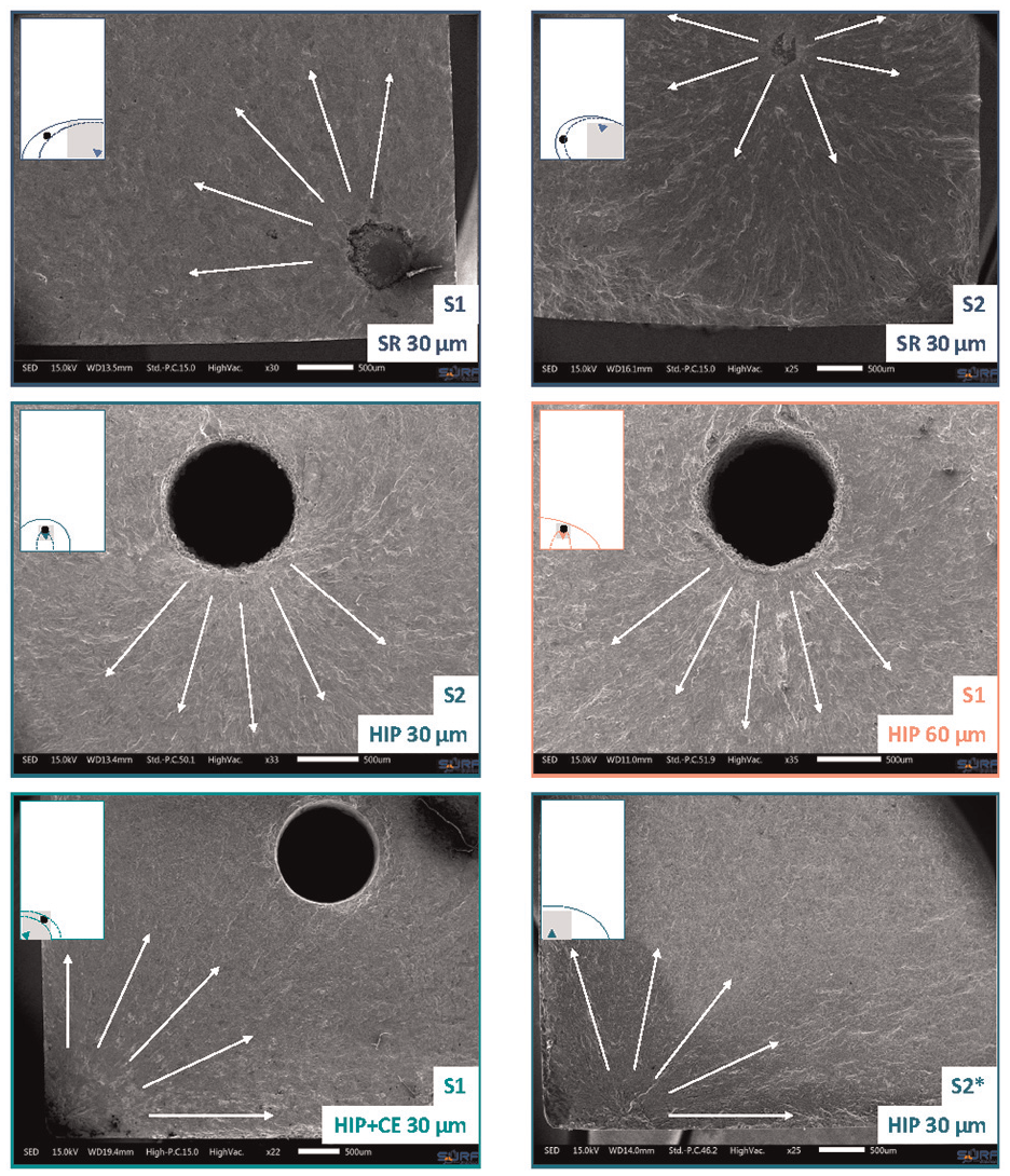
Fatigue initiation sites on the fracture surface of Ti-6Al-4V coupons processed using different layer thicknesses and post-processes.
Figure 14 presents a summary of the schematic representations of the fracture surfaces. Two severe material imperfections (see also Figure 13, S1 and S2) caused fatigue initiation in the stress relieved coupons produced using a layer thickness of 30 µm. The fatigue crack in the third specimen initiated from the capillary surface roughness, all of them at roughly the same stress level at the initiation location (
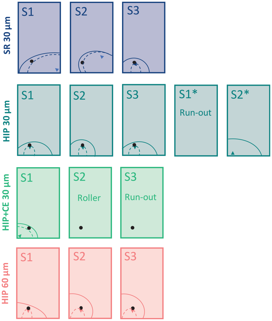
Graphical representation of observed fracture surface with indication of fatigue initiation location (triangle), fatigue crack size upon detection by the eSHM system (dashed line) and at final fracture (solid line). eSHM: effective structural health monitoring.
Therefore, three more coupons with embedded SHM system were post-processed using a CE treatment, which resulted in significantly reduced surface roughness of the embedded capillary. The fatigue strengths of these coupons were similar to the benchmark values of coupons without embedded capillary. Only a single specimen failed due to fatigue in the test zone, while a second specimen failed due to local stresses around the rollers, and a third specimen had not failed at run-out. The single fatigue failure initiated from a subsurface location, very close to the milled outer surface where the highest tensile stresses are expected. The similarity of the fatigue initiation site w.r.t. the benchmark is very remarkable; that is, the sample with capillary (see Figure 13, bottom-left) compared to the one without (see Figure 13, bottom-right).
It can thus be concluded that the addition of an untreated capillary limits the fatigue strength as the capillary became the fatigue initiation site at lower fatigue strengths. The CE treatment seems to have resolved the stress concentration at the capillary as fatigue strength is restored to the reference fatigue strength of samples without capillary. The fatigue initiation sites have shifted back to the remaining subsurface defects, just as in the reference samples, marking the capillary insignificant for the fatigue strength.
eSHM system performance
Prior to the fatigue testing, the capillary of the eSHM system was set to a vacuum (0.1–0.2 bar absolute) and sealed (see Figure 15 (right)). During the actual fatigue testing, there is no active pressurization, only a single pressure sensor is continuously monitoring the pressure level inside the capillary. The pressure essentially remains unchanged throughout the majority of the test, although minor fluctuations may be observed, which may be caused by the deformation of the sample (see Figure 15 (left))49,50 or thermal influences such as frictional effects causing the sample to heat up. These small pressure fluctuations remain well below 0.1 bar and therefore do not interfere with the fatigue crack detection principle, which is triggered when the capillary pressure exceeds 0.85 bar absolute pressure. A pressure leakage through the connections with the pressure sensor and check valve could result in false positives as is subtly present in Figure 15 (right, condition 30 µm HIP + CE).
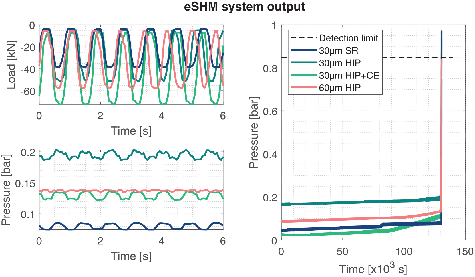
eSHM system output during the fatigue testing. The capillary pressure varies dynamically with the loading, albeit remaining at an underpressure till a fatigue develops.
Figure 16 presents the recorded pressure data during the last minute (left) and last second (right) of the test prior to fatigue crack detection by the eSHM system. Ultimately, when the fatigue crack has initiated and propagated such that the fatigue crack interconnects the capillary with the outer specimen surface, a leak flow will alter the capillary pressure. This can be observed as the onset of the steep pressure rise around timestamp 50–60s in the left picture of Figure 16. A closer look at the last second prior to fatigue crack detection reveals small fluctuations in the pressure data (see Figure 16 (right)). These correspond to the sinusoidal loading pattern of the fatigue test bench. The pressure recording of the 60 µm HIP’ed coupons differs significantly from the others, which is most likely related to a false calibration of the pressure sensor, setting atmospheric conditions at around 0.85–0.9 bar, thereby barely reaching the pre-set detection limit of the eSHM system even when fully conditioned at atmospheric pressure. This error could have resulted in a false negative test result.
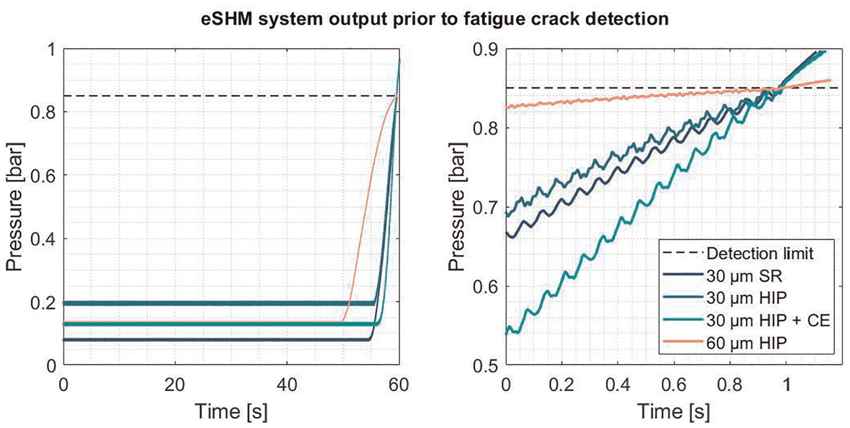
eSHM system output prior to fatigue crack detection for the last 60 s (left) and last second (right). eSHM: effective structural health monitoring.
Including the single point of attention described here above, all fatigue tests were successfully stopped by the eSHM system prior to the final fracture of the coupon. Figure 16 presents a pressure recording for each coupon configuration, clearly presenting the capillary pressure level is crossing the pre-set limit of 0.85 bar, after which the fatigue test bench was stopped. This event can also be observed from the pressure data, as from this pressure level on, no more fluctuations can be observed in the pressure data. The dynamic loading pattern is stopped once the stop procedure is triggered by the eSHM system, leaving the test setup to hold the mean level of the sinusoidal excitation. Subsequently, the sample is still loaded, and the fatigue crack still opened, which results in a further gradual increase of the pressure level inside the eSHM capillaries. This behaviour can be observed after passing the 1 s timestamp in Figure 16 (right).
Discussion
The current work has investigated the effect of different layer thicknesses (30 and 60 µm) as well as SR, HIP and CE post-processes on the surface roughness, quasi-static and fatigue behaviour of Ti-6Al-4V coupons processed by PBF-LB. The studies are related to the development of the eSHM system, comprising of embedded capillaries of which the surface roughness is critical not to initiate fatigue initiation. The eSHM system has been challenged to detect fatigue cracks prior to final rupture during fatigue testing, and the influence of the capillary presence on the fatigue initiation has been investigated.
While the SR and HIP post-process did not influence the surface condition, a 10 min immersion in HF-based has removed approximately 50 µm of material, thereby significantly reducing surface roughness by removing partly sintered particles. This CE post-process has been found to be as effective on the inner surface of the 1 mm diameter capillaries of the eSHM system, as on the outer surface of the tensile fatigue samples. The roughness metrics (
The quasi-static tensile test results have shown a distinct decrease in YS and UTS as well as an increase in ductility when a HIP post-process is considered instead of SR. The additional CE post-treatment did not affect neither the YS nor UTS but resulted in improved ductility. Besides a marginal decrease in the Young’s modulus when 60 µm layers are considered, no further significant differences could be observed in the tensile properties of samples fabricated using a 30 and 60 µm layer thickness.
The fatigue testing on the tensile sub-coupons revealed a gradual increase in the fatigue strength when post-processing by means of SR, HIP and HIP + CE and found almost no noticeable differences between sub-coupons processed by means of a 30 and 60 µm layer thickness. Most apparent is the very distinct spread on the fatigue strengths reported for the SR conditions, as opposed to the HIP’ed conditions. The fractographic analysis revealed that fatigue initiation occurred on the outer surface for all specimens. Although sample densities were reported very similar across all sample batches and all above 99.6%, the presence of gas inclusions has only been observed on the fracture surface of the samples that were stress-relieved.
Similarly, also four-point bending coupons were fatigue loaded to evaluate the eSHM system performance. Two coupons without embedded capillary were tested and served as benchmark for the remaining tests with embedded capillary. While the first one survived all 1 million cycles at 1100 MPa and was therefore considered as run-out, the second sample failed at a fatigue strength of 1097 MP. The fatigue crack had initiated from a subsurface defect, close to the most tensile-stressed outer surface. When considering coupons with embedded capillaries of the eSHM system in as-built surface condition, all coupons presented very similar fatigue strength in between 500 and 600 MPa (stress evaluated on the initiation site). While two out of three fatigue cracks in the SR samples initiated from a material imperfection, fatigue systematically initiated from the capillary surface in HIP’ed samples (both 30 and 60 µm). The similarities in test results between these six HIP’ed coupons is striking in all aspects but clearly demonstrates the clear need for additional post-treatment using CE to reduce capillary surface roughness and avoid premature fatigue initiation by avoiding stress concentrations on the capillary surface.
Subsequently, coupons were post-processed using both a HIP and CE post-treatment that should ultimately solve the issue of residual porosity (HIP) and surface roughness (CE) and thereby increase the overall fatigue strength of the coupons with embedded capillary. A first coupon failed at 1135 MPa, while the two others may be considered as run-out as they approached the maximum test capacity of the test bench or failed as a result of local stress around the contact points with the roller. By doing so, the test results approached the benchmark and subsequent fractographic investigation has shown that the capillary did not contribute to the fatigue initiation. The single coupon that suffered a fatigue failure saw its fatigue crack initiated from a sub-surface material imperfection. The fatigue initiation site and fatigue behaviour show strong similarities with the benchmark coupons. From these observations, it could be concluded that by improving the surface roughness state of the embedded capillary, the embedded eSHM technology should not be expected to reduce the fatigue strength of the component.
During the before-mentioned fatigue testing, the eSHM system was actively used to inspect the component and stop the fatigue test at fatigue crack detection. In all cases, the test was successfully stopped prior to the final rupture of the component. A closer look to the actual pressure behaviour has revealed that a single experiment was close to a false-negative test result, most likely related to a wrong calibration of the pressure sensor.
Conclusion
The eSHM system has the goal to detect fatigue cracks in additively manufactured components. Its principle relies on the layer-wise fabrication of AM to integrate capillaries in the component. These capillaries are pressurized prior to component usage and serve as the sensing element of the SHM system. To avoid fatigue initiation to occur on these capillaries, the surface roughness of the capillary must be improved w.r.t. as-built surface condition. The current study has therefore investigated the effect on surface roughness, quasi-static and fatigue properties of Ti-6Al-4V coupons processed by means of PBF-LB (30 and 60 µm) and post-processed using a SR, HIP and CE treatment. Also, the eSHM system performance has been evaluated. The following conclusions were drawn from the study
The surface roughness metrics were halved by the additional CE process, while the SR and HIP did not affect surface roughness condition. The CE post-process has been found to treat as effectively the inner capillary surface as the outer surface of the specimens.
Although the specimens processed using a 30 and 60 µm layer thickness present equal roughness metrics, the contribution of the welding beats of the fabrication process is more pronounced in the 60 µm case.
Apart from the Young’s modulus, the quasi-static material properties of Ti-6Al-4V were mostly influenced by the SR and HIP post-process. It was found that the HIP post-process, as opposed to the SR post-process, resulted in a lower YS and UTS but presented improved ductility. The additional CE post-process only resulted in a further improvement of the ductility.
The influence of the layer thickness on the quasi-static material properties has also been investigated. The Young’s modulus has been found to be systematically lower for the 60 µm layer thickness, and this for all post-process conditions (SR, HIP and HIP + CE). All other quasi-static material properties were mostly unaffected by the layer thickness.
The tensile fatigue behaviour of the specimens was investigated in as-built surface condition (no finish milling), and specimens were treated with either a SR, HIP and HIP + CE post-process prior to the test. The reported fatigue strength has been found to increase from a SR, over HIP to HIP + CE post-treatment. All fatigue cracks have initiated from the outer surface, indicating that the surface condition played a critical role in the fatigue initiation phase. The additional CE post-process has reduced the outer surface roughness state, which resulted in a higher fatigue strength.
The four-point bending fatigue tests on specimens with embedded capillary presented a very similar observation as the tensile fatigue tests. Besides some material imperfections in SR specimens, the capillary has been systematically found to be the root cause of fatigue initiation as long as its surface conditions remained in as-built surface condition. The additional CE post-process reduced the capillary surface roughness, which in turn resulted in a vast improvement of the fatigue strength, thereby equalizing to the benchmark of samples without embedded capillary.
The eSHM system performance was challenged to detect the presence of fatigue cracks prior to component failure. In all tests, the eSHM system did so successfully, and no differences in eSHM system performance were observed as a result of the various post-processes or the use of a different layer thickness. However, a single experiment was very close to a false negative result due to a wrong calibration of the pressure sensor.
Footnotes
Declaration of conflicting interests
The author(s) declared no potential conflicts of interest with respect to the research, authorship, and/or publication of this article.
Funding
The author(s) disclosed receipt of the following financial support for the research, authorship, and/or publication of this article: The research work was partly financed by the Research Foundation – Flanders (FWO) under ref. 12ZV920N.