
Abstract
This paper presents a hybrid structural health monitoring (SHM) approach that combines the high damage sensitivity of guided waves with the temperature resilience of modal analysis, enabling damage detection in plates with varying material properties under different temperature conditions, without the need for extensive baseline data or temperature compensation. To validate this approach, a series of experiments were designed and carried out on plates equipped with four Piezoelectric transducers to actuate and receive guided waves to obtain the transmissibility functions (TFs) of structures under different temperature conditions ranging from 20°C to 60°C. The changes in correlation coefficients of TFs between the current and baseline states were selected as damage-sensitive features, with the Mahalanobis distance (MD) calculated as a damage indicator. The proposed method was experimentally verified on an aluminum plate (M1), a quasi-isotropic composite plate (M2), and an anisotropic curved composite plate (M3). Results demonstrate high accuracy in detecting damage at five different locations on the M1 plate, both inside and outside the sensor coverage area, over the temperature range of 20°C–60°C. Furthermore, the proposed method successfully detected damage on the M2 and M3 plates over temperature ranges of 20°C–40°C and 20°C–30°C, respectively. Finally, the performance of the proposed methodology was evaluated using an alternative actuator, thereby mitigating potential uncertainties arising from variations in sensor locations. This work highlights a practical and efficient SHM solution, offering accurate damage detection across variable environmental conditions with a simplified experimental setup and minimal baseline requirements.
Keywords
Introduction
Structural health monitoring (SHM) is an emerging non-destructive testing (NDT) method and has been receiving much attention in the last two decades. It uses embedded sensors for in-service damage detection, alerting at the inception of damage and predicting the remaining service life of engineering structures. 1 A key advantage of SHM is its capability to monitor the health of structures without interrupting their operation compared with traditional NDT methods, which enables a reduction of maintenance cost and time. As such, SHM systems have been implemented in various fields including aerospace,2,3 wind turbines, 4 bridges, 5 rail, 6 and civil.7,8 Many SHM methods have been developed for aerospace structures in recent years, and the most commonly used methods can be categorized into guided wave-based SHM (GWSHM) and vibration-based SHM (VSHM) by the sensor type.9,10
GWSHM methods use mounted piezoelectric (PZT) sensors to actuate and receive guided waves, detecting damage by comparing signals from the structure’s current state to a baseline state. The growing interest in GWSHM methods arises from their ability to transmit guided waves with minimal energy loss over considerable distances and their sensitivity to even subtle structural changes.11–15 However, a major limitation of GWSHM methods is their susceptibility to variations in environmental and operational conditions (EOC), particularly to temperature due to the thermal sensitivity of guided waves. For example, aircraft operates in temperature ranges from −40°C to 60°C, and temperature-induced changes in guided waves may obscure damage-induced changes, thereby restricting the practical application of GWSHM methods. Consequently, extensive efforts have been made to mitigate the impact of temperature on GWSHM methods in recent years.2,16 Two widely used methods are optimal baseline selection (OBS) 17 and baseline signal stretch (BSS) methods. 18 The OBS method selects the waveform that best matches the current signal from large baseline signal datasets obtained from different temperatures. OBS has demonstrated high accuracy in damage detection across a broad temperature range. However, OBS requires a large baseline signal database, which may not always be feasible in real-world applications. In aerospace, for example, collecting sufficient baseline signals to cover the full operational temperature range can be resource-intensive and time-consuming. This dependence on a comprehensive database also limits OBS’s scalability, as environments with unpredictable temperature shifts require frequent data updates. By contrast, the BSS method only needs one baseline signal to compensate for the temperature, which corrects the baseline signal to match the current signal using the stretch factor.18,19 However, BSS faces limitations when temperature-induced changes are nonlinear, 20 as its stretch factor primarily accounts for linear adjustments, which can reduce accuracy under complex thermal conditions. This is because the stretch factor is designed to correct linear changes in the signal, whereas real temperature variations often introduce more complex, nonlinear modifications to wave propagation.
VSHM methods detect damage by identifying changes in the modal parameters of structures, which can be classified based on natural frequency, 21 modes shape, 22 and frequency response function (FRF).23,24 These approaches are resilient to EOCs, as variations in modal properties due to factors like temperature and humidity are typically minimal or predictable.25–29 Therefore, VSHM methods have also attracted attention in the SHM field.30–34 Salawu 27 and Zhang et al. 29 emphasized the robustness of mode shapes, noting that mode shapes often remain relatively unchanged even under varying environmental conditions, thus providing an environment-insensitive parameter basis for VSHM. Zhao et al. 28 further supported this perspective, demonstrating that even with significant temperature and humidity fluctuations, mode shape-based damage detection methods can effectively distinguish between healthy and damaged structural states. Despite these advancements, the main challenge of these methods is their limited sensitivity to minute damage.35,36 In addition, modal parameters, especially mode shapes, are typically only sensitive to the local damage, 34 and fail to provide a reliable result for SHM of large structures.
Given these constraints, a hybrid approach that leverages the strengths of both GWSHM and VSHM offers a promising solution to address each method’s limitations. This combined approach can integrate GWSHM’s sensitivity to subtle structural changes with VSHM’s resilience to environmental variations, thereby enhancing damage detection reliability across diverse EOCs. In our previous work, 37 we demonstrated the feasibility of integrating guided wave and vibration-based methods for damage detection and localization, showing that combining these signals yields more stable and precise monitoring and localization results. However, previous experiments utilized separate acquisition systems for both PZT and accelerometer sensors, which added to the complexity of the setup. Thus, a simplified sensing scheme is necessary. For example, if PZT transducers could perform modal shape measurements traditionally achieved by accelerometers, this would significantly streamline the experimental process. Recent studies have shown the feasibility of using PZT transducers in low-frequency modal analysis, traditionally dominated by accelerometers. For instance, Wang et al. 38 conducted a detailed analysis of the application of PZT transducers in modal testing of cantilever beams. Their study examined four types of sensor-actuator pairs: accelerometer–point force, accelerometer–PZT, PVDF (polyvinylidene fluoride)–point force, and PVDF–PZT. The results demonstrated that each combination effectively captured natural frequencies and damping ratios, theoretically validating the use of PZT in experimental modal testing of cantilever beams. Similarly, Zonzini et al. 39 presented a heterogeneous sensor network incorporating MEMS accelerometers and PZT for effective and low-cost modal analysis of structures. Their experiments verified the physical relationship between data collected from PZT transducers and accelerometers, confirming the feasibility of using PZT for low-frequency modal analysis. Building upon this technical feasibility, exploring features that can enhance SHM robustness under varying EOCs becomes essential. A particularly promising direction in hybrid SHM is the extraction of temperature-insensitive features (TIFs) that remain sensitive to damage while minimizing sensitivity to EOCs, which have not yet been tested. Transmissibility functions (TF) have been demonstrated to be less sensitive to temperature fluctuations in some research,40,41 and it is a mathematical relationship between two outputs and is insensitive to the influences of the input variation, making them well-suited for the PZT system.42–44 Another advantage of TF is its capability to detect damage without the need to develop any analytic or discretized model of the structure.45,46 As such, TF-based damage detection may have the potential to address the existing challenges in temperature compensation. However, limited research has explored the application of TF-based methods for damage detection in this area.
To validate the proposed hybrid SHM approach and the application of TFs as TIFs, a series of experiments are conducted, utilizing plates equipped with four PZT transducers to generate and receive guided waves and derive TF values. Changes in the correlation coefficient of TF between current and baseline states are selected as damage-sensitive features (DSFs). These DSFs are then used to calculate the MD as an indicator of structural damage. The proposed method is rigorously tested on an aluminum plate, a quasi-isotropic composite plate, and an anisotropic curved composite plate. The main novelty of this work lies in:
(I) Hybrid SHM methodology: This research introduces a hybrid SHM approach that combines the high sensitivity of GWSHM with the temperature resilience of VSHM, enabling accurate damage detection under varying temperature conditions.
(II) Multifunctional use of PZT transducers for modal analysis: PZT transducers, typically used for GWSHM, are applied here for low-frequency modal analysis, eliminating the need for separate accelerometers and reducing system complexity and cost. The multifunctional PZT sensors support passive impact detection, active damage detection, and automatic tracking without extra power sources, enhancing the practicality of hybrid SHM systems in field applications.
(III) Minimal baseline data requirement: Unlike previous temperature compensation methods, the approach presented in this research requires only a single baseline signal for effective damage detection over a broad temperature range.
(IV) Exploration of TF-based damage detection: This study underscores the potential of TFs in addressing the challenges posed by temperature compensation in SHM, offering a promising strategy for damage detection in structures subjected to varying temperature conditions.
The remainder of this paper is organized as follows. First, the methodology is presented, which includes data acquisition, feature extraction, decision-making, and performance analysis. Following this, the experimental details are presented. Subsequently, damage detection and uncertainty quantification are discussed. Finally, the paper concludes with a summary of the overall evaluation of the methodology.
Methodology
This work aims to differentiate between damaged and intact structures across varying temperature conditions. The key challenge lies in identifying whether changes in signal patterns on structures stem from damage or temperature variations. To accomplish this objective, all stages of the proposed methodology are outlined in Figure 1, including data acquisition, feature extraction (comprising TF computation, damage index vector derivation, and MD computation), outlier analysis, and performance evaluation.
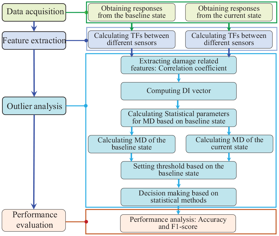
The framework of the proposed damage detection methodology.
Data acquisition
Following the outlined procedure in Figure 1, the initial stage involves gathering data at varying temperatures, described in the section “Experiment setup.” The data obtained at a specific temperature is defined as a signal vector


where
Feature extraction
Transmissibility functions
Following data acquisition, the next step is feature extraction, which is the most important step in damage detection. Previous studies2,3 typically involved extracting some DSFs such as time of arrival to detect damage. However, due to the temperature sensitivity of guided waves, such methods may prove unreliable in environments with fluctuating temperatures. Therefore, it is imperative to select features that are sensitive to damage while remaining resistant to temperature fluctuations for effective damage detection across varying temperatures.47,48 Thus, TFs are used to detect damage in this research, and the calculation process of TFs is summarized in Figure 2.
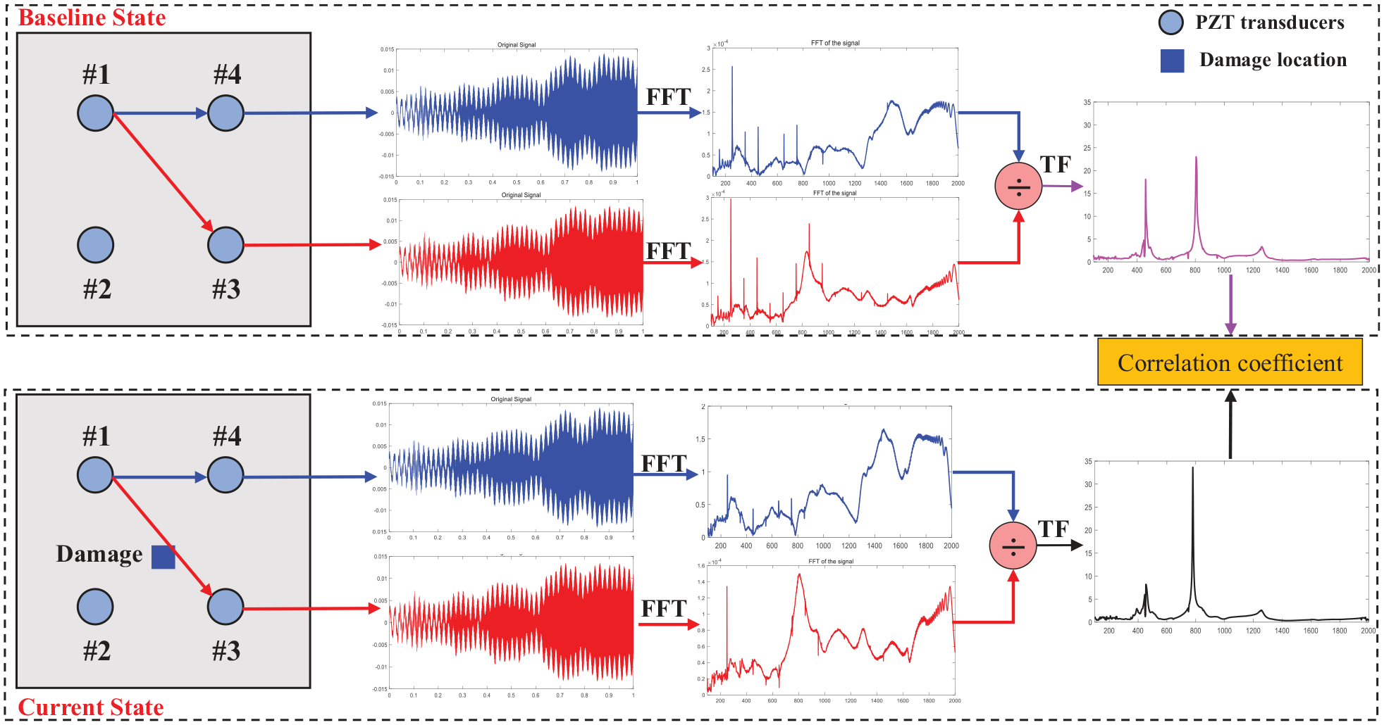
The process of feature extraction.
As is illustrated in Figure 2, TFs are defined as the ratio between two measured outputs in the frequency domain, 49 which is expressed as follows:
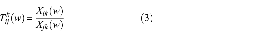
where
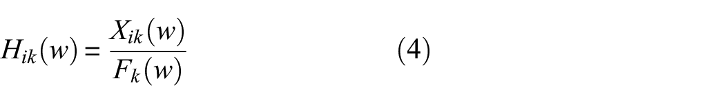
where
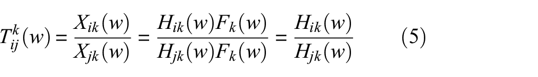
In FRF, peaks correspond to the resonant frequencies of structures, and dips represent the anti-resonant frequencies of structures. Based on Equation (5), the dips in FRF correspond to the peaks and the dips in TF. Therefore, the TF is capable of reflecting the modal properties of structures.
Since the TF is the ratio of the two measured outputs, a minimum of three PZT transducers is required to obtain one TF of the host structures. Specifically, one is used as the actuator to send signals, while the other two serve as sensors to receive these signals. Based on the signals from the two measured outputs, two reciprocal TFs are obtained, both reflecting identical modal parameter information. As such, only one of these TFs is used as a feature for damage detection. The relationship between the number of sensors and
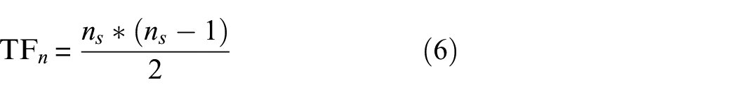
where
Damage-related feature
After obtaining TFs from different sensor pairs, the damage-related features should be extracted from these TFs. In this study, the correlation coefficient between baseline
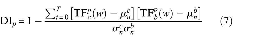
where
Decision-making: outlier analysis
After obtaining the
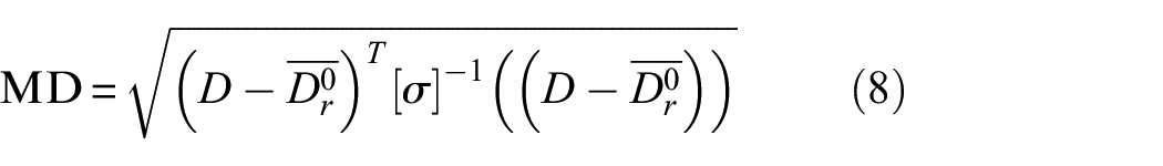

where
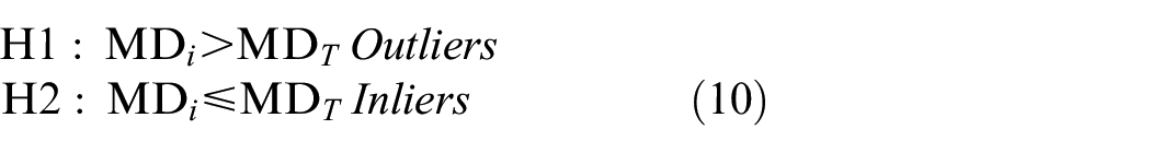
As shown in Equation (10), samples are labeled as outliers (damaged) when the
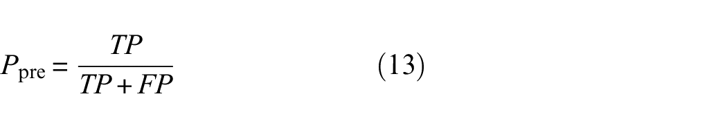
Performance analysis

where
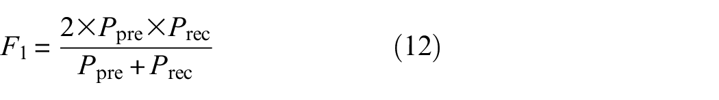
The range of
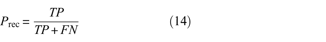
The recall
Experimental setup
Test specimens
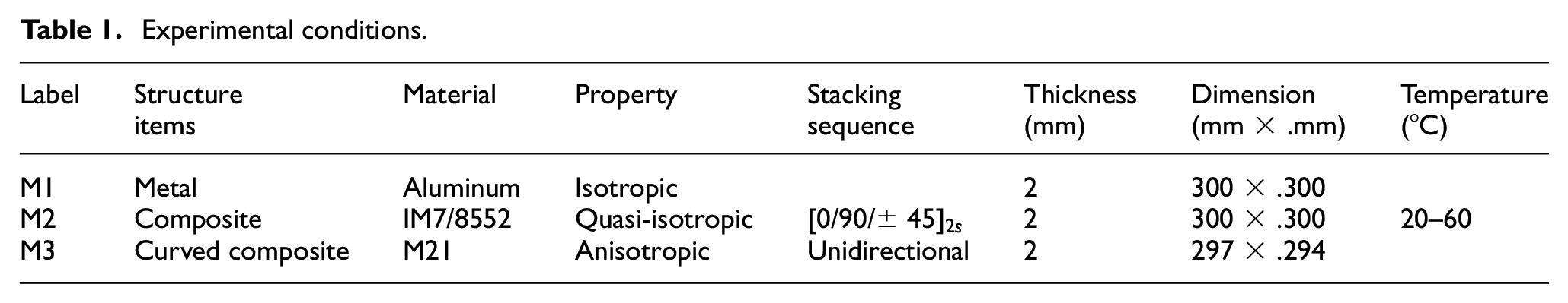
Three plates with different materials and properties are used in the experiment to validate the proposed method. Specifically, M1 is an aluminum plate, which is a typical isotropic structure. IM7/8552 is used to manufacture a composite plate M2, which is quasi-isotropic due to the symmetrical and balanced lay-up. M3 is an anisotropic curved composite plate, and it is manufactured by 16 layers of M21 prepreg plies. M1 and M2 are the same dimensions (300 × 300 mm) and the size of M3 is 297 × 294 mm. The working temperature of all plates is between 20°C and 60°C. The properties and working conditions of these plates are summarized in Table 1.
Experimental conditions.
The selection and bonding process of transducers
In this study, PZT transducers are used for guided wave propagation. For the installation of PZT, they are first attached to the plates by two layers of thermoplastic films and adhesive tapes, the plates with the PZT transducers are then put in the vacuum-heated table for bonding. The bonding process is carried out in a vacuum environment at 140°C for an hour, the temperature is then turned off, and the vacuum environment is kept making the thermoplastic film fully melt.
Experimental platform setup
The actuation signal: A 12 V peak-to-peak linear chirp signal, sweeping in frequency from 500 to 2000 Hz, was generated by a National Instruments PXI 5412 waveform generator and applied to a PZT over a 1000 ms window. The sensor response was recorded using a PXI 5105 oscilloscope at a 1 MHz sampling frequency for 1000 ms to ensure complete signal capture. Each test was repeated five times to minimize environmental interference.
The experimental platform: The experimental platform is shown in Figure 3, and M2 is taken as an example of the setup. The plate is lifted by the fixture and strings to gain more freedom, and four PZT transducers are symmetrically bonded to all three plates in a square configuration with sides of 120 mm. A heating blanket is placed under the plate to control the temperature. In addition, two temperature sensors, each with a resolution of 0.1°C, are attached on opposite sides of the plate to monitor the real-time temperature. Experiments were carried out with a temperature difference of less than ±0.2°C between two temperature sensors.
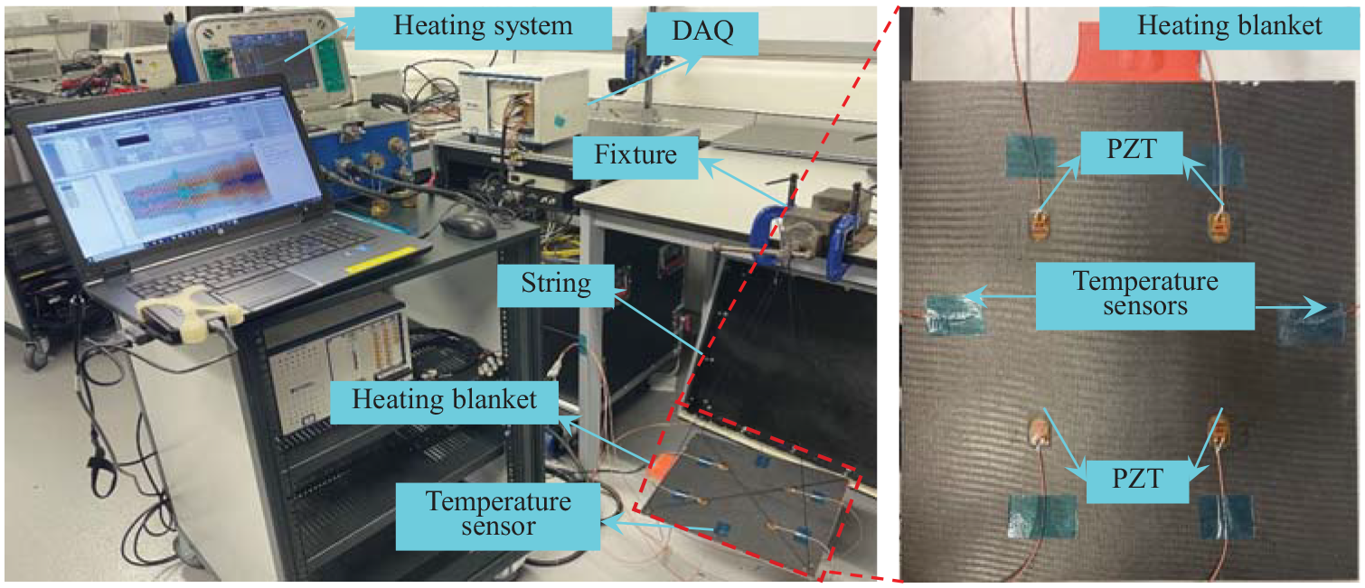
Schematic diagram of the experimental setup.
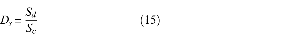
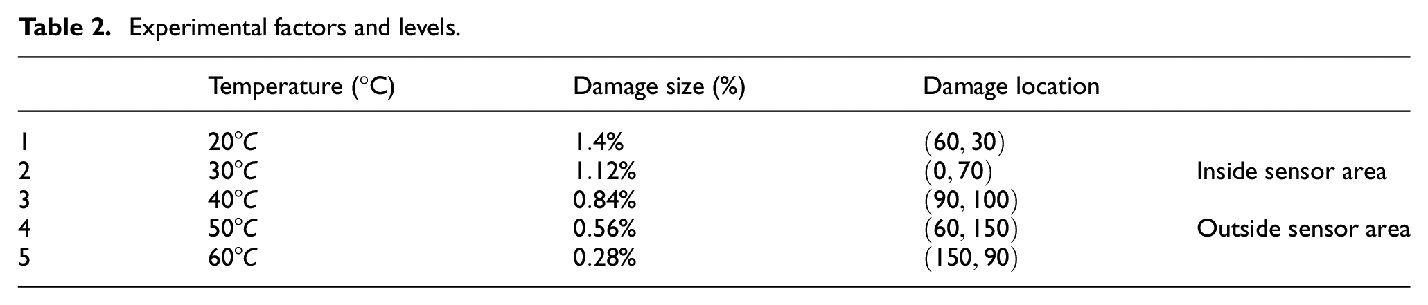
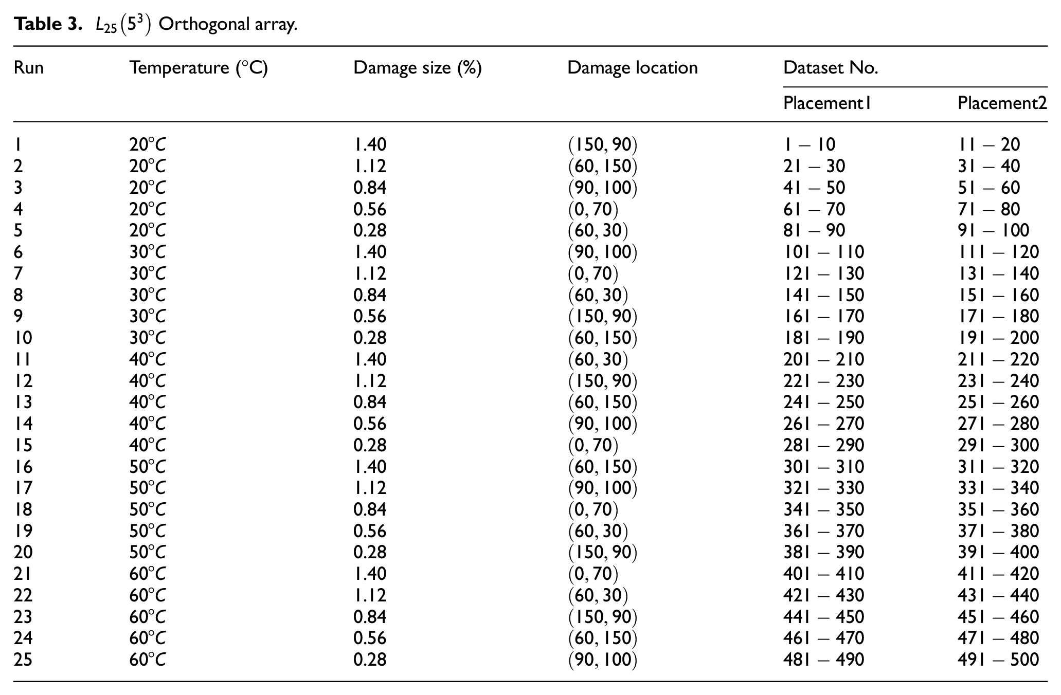
In addition to different types of materials, different damage sizes are also set to investigate the minimum damage that can be detected by the proposed method, and five damage locations are used to demonstrate the applicability of the method. Three of these locations are located inside the area covered by PZT transducers, another two are located outside this area. Considering that the plates are irreversible after damage, masses were used to simulate the damage, and different sizes and locations of damage are shown in Figure 4.
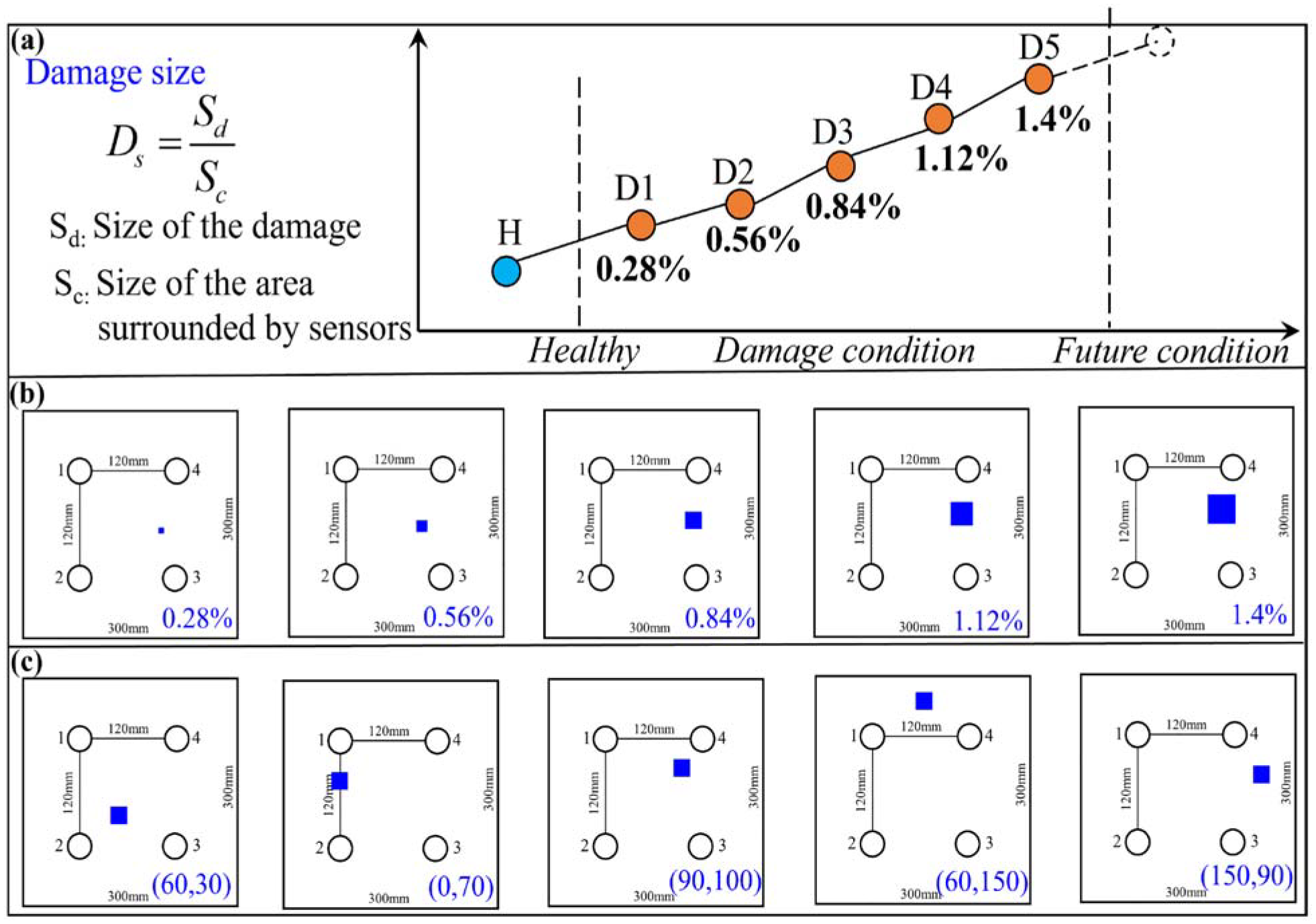
Different experiment conditions: (a) the definition of the damage size, (b) damage with different sizes on the plates, and (c) damage positions inside and outside the sensor area.
where
Experimental factors and levels.
Damage detection results
Temperature and damage effects on TFs
Many previous studies on TF-based methods have shown that temperature changes minimally affect the modal property of structures, especially at low frequencies. However, damage significantly affects the modal property of structures. As mentioned in the previous section, features extracted in this research should be damage sensitive and temperature insensitive. Therefore, the effects of temperature and damage on the TF are first studied. TFs (obtained by sensors 2 and 3) of M1, M2, and M3 in intact condition and damage with different sizes and locations are reported in Figures 5 to 7. Solid and dashed lines represent the baseline and current TFs.
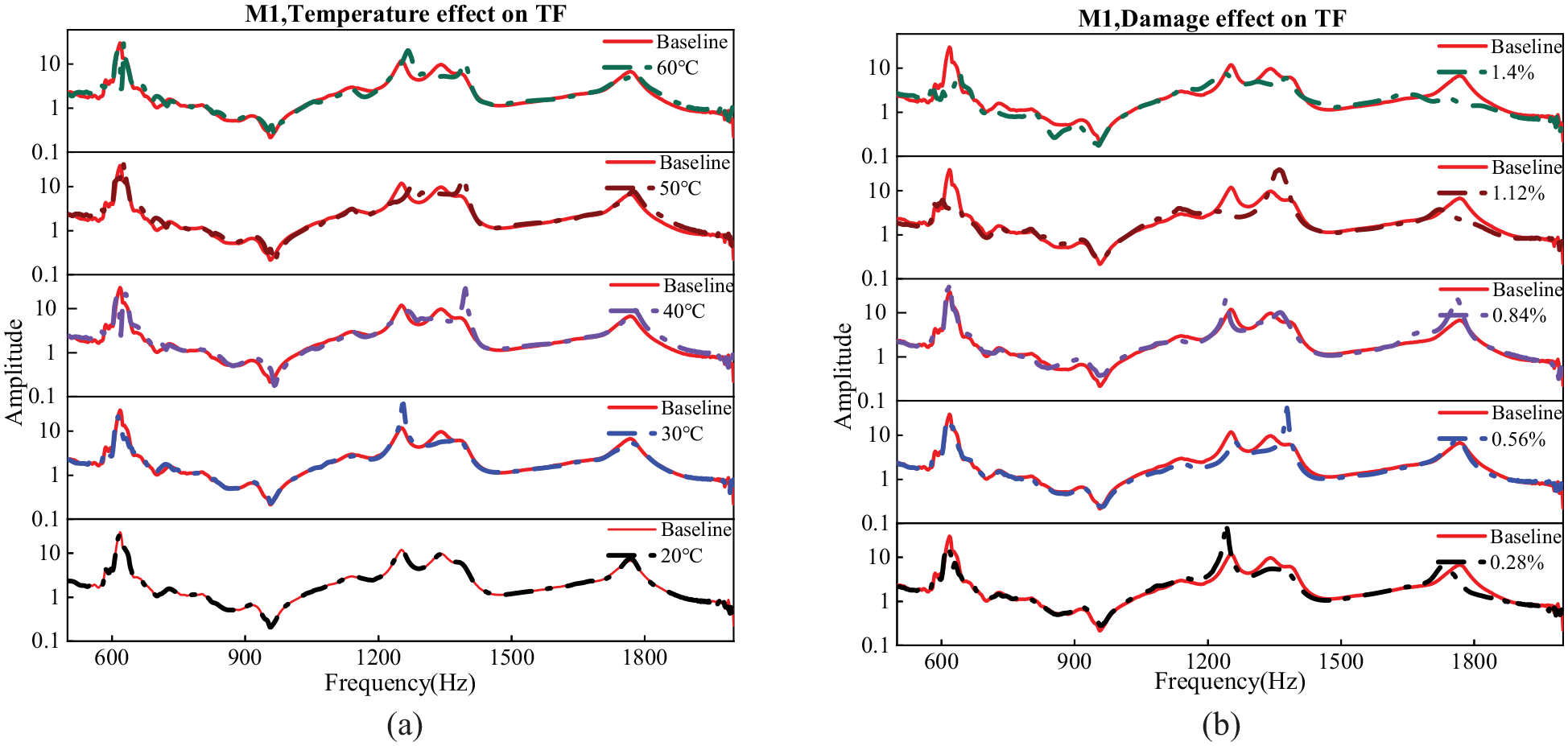
TF of M1 obtained by sensors 2 and 3 under different conditions: (a) the effect of different temperatures (20°C, 30°C, 40°C, 50°C, and 60°C, from bottom to top, respectively) on TF and (b) the effect of damage sizes (
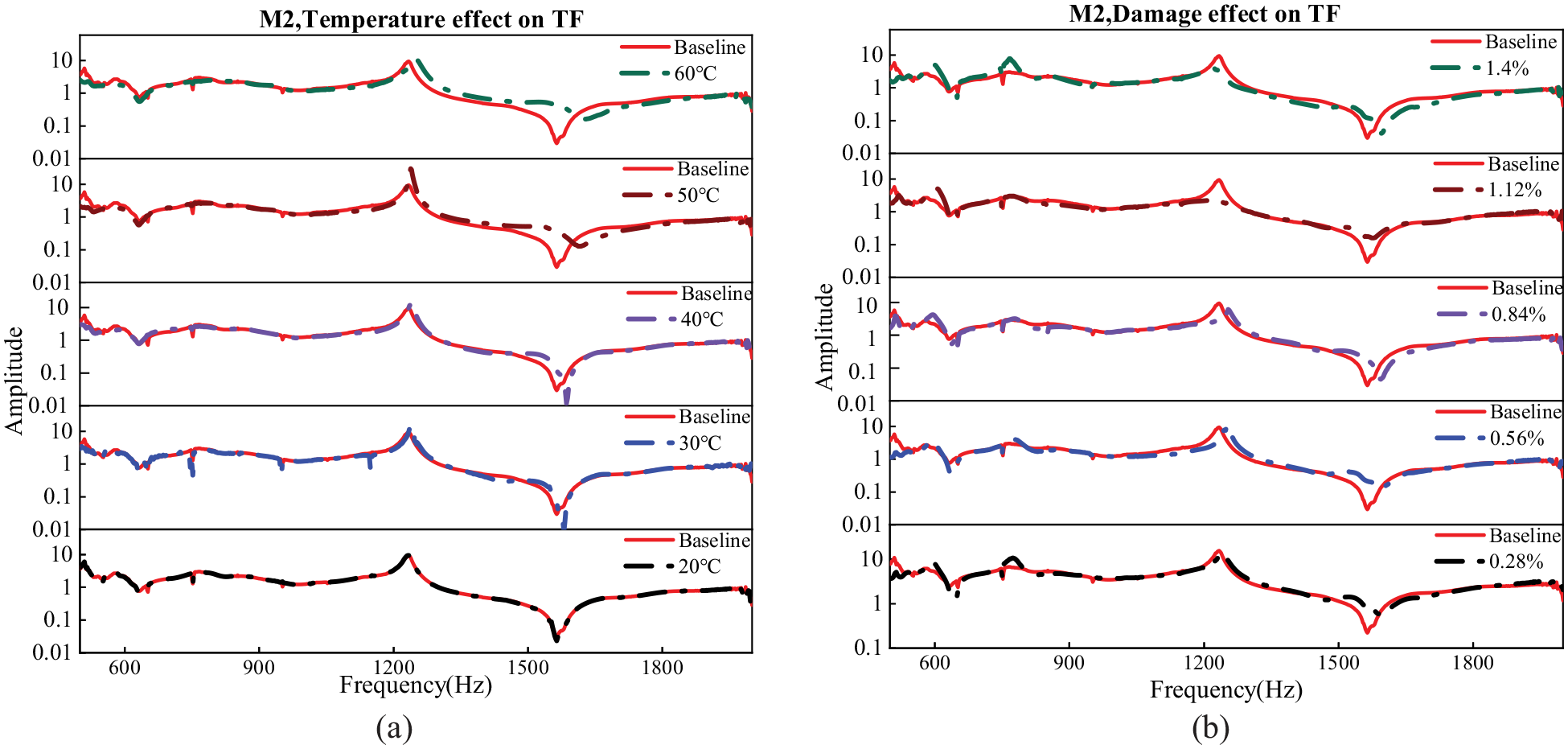
TF of M2 obtained by sensors 2 and 3 under different conditions: (a) the effect of different temperatures (20°C, 30°C, 40°C, 50°C, and 60°C, from bottom to top, respectively) on TF and (b) the effect of damage sizes (
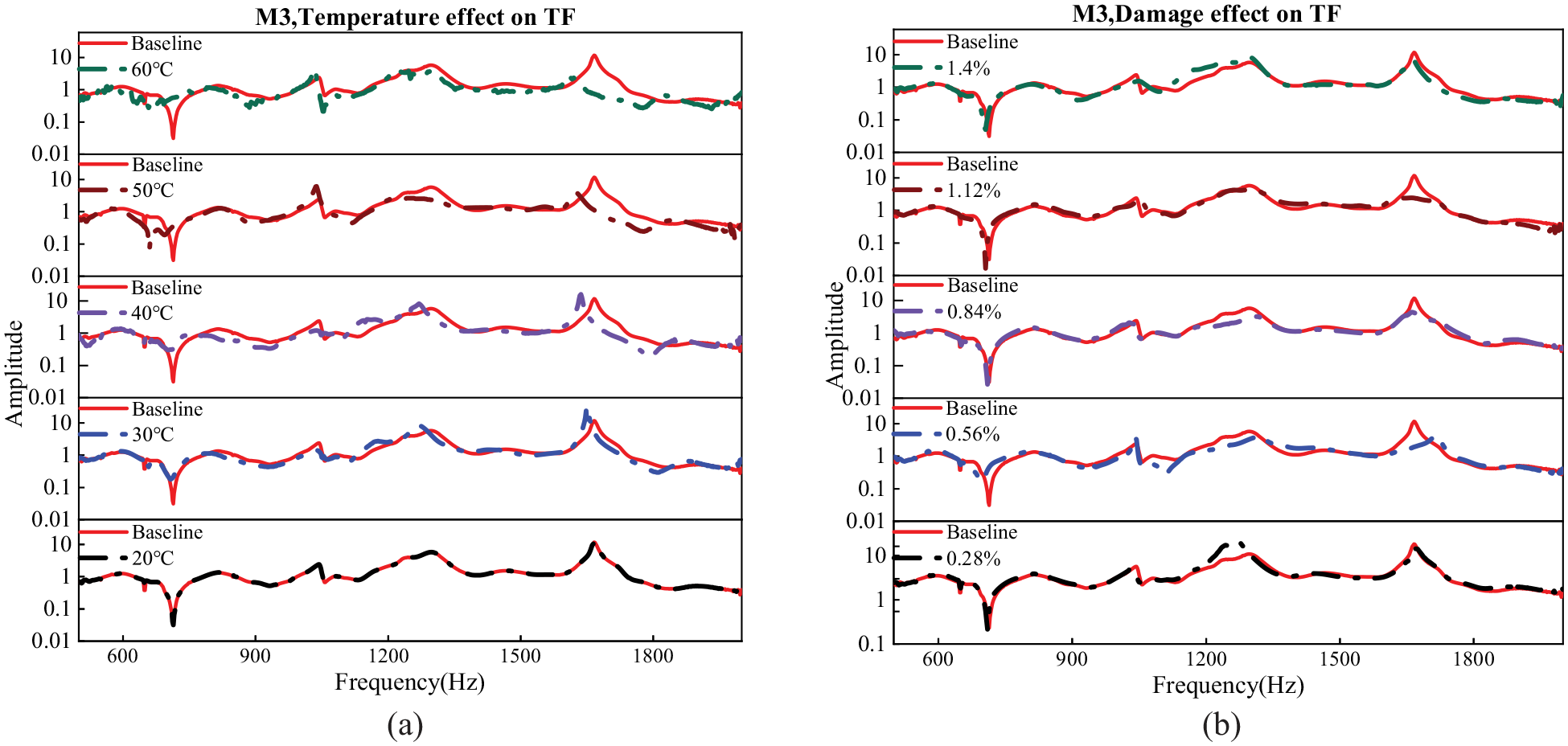
TF of M3 obtained by sensors 2 and 3 under different conditions: (a) the effect of different temperatures (20°C, 30°C, 40°C, 50°C, and 60°C, from bottom to top, respectively) on TF and (b) the effect of damage sizes (
Figure 5(a) shows that the TF values fluctuate when the temperature increases, particularly within the range of 1200–1500 Hz, and this fluctuation gradually increases with increasing temperature. This is because temperature changes affect the material properties, such as thermal expansion, elasticity modulus, damping, and nonlinear properties, all of which affect the modal properties. However, upon the introduction of damage, there are obvious variations in both amplitude and phase within some frequency bands. For example, the amplitude of TF in the vicinity of 600 Hz remains almost the same in response to temperature fluctuations (Figure 5(a)), but a noticeable variation is observed when the damage size is 1.12% and 1.4% (Figure 5(b)), respectively. In addition, the peak at approximately 1800 Hz demonstrates notable variations with the smallest damage size of 0.28%.
For the TFs of M2 obtained by sensors 2 and 3, as illustrated in Figure 6, an increase in temperature results in a gradual change in TF compared to the baseline. This is due to the fact that in addition to causing changes in material properties (e.g., modulus of elasticity, stiffness, tensile, and compressive strength), the increase in temperature also changes the internal stresses between different composite layers, which leads to changes in the vibration response and the TF of the structure. As shown in Figure 6, the peak around 1500 Hz remains almost constant at
Wave propagation in the M3 plate is more complex due to its curved shape and anisotropic properties. Figure 7 illustrates the challenges of distinguishing temperature effects from damage effects based on changes in specific frequency ranges. As shown in Figure 7(a), TFs increase gradually with rising temperature, particularly within the 600–900 Hz and 1500–1800 Hz ranges. In terms of damage effects (Figure 7(b)), TFs show slight changes between 500 and 1000 Hz after damage introduction, while at higher frequencies (1500–1800 Hz), the peaks in both frequency and amplitude change significantly. Given the complexity of the M3 plate, both temperature and damage significantly influence TFs, making it difficult to isolate their individual impacts based solely on observed changes in Figure 7. Consequently, the DI defined in Equation (7) is essential for reliably assessing these effects and achieving accurate damage detection under different temperatures.
Detection results
Results summarized in the previous section make it possible to identify temperature-induced effects and damage-induced effects using correlation coefficients. The primary objective of this research is to detect damage under different temperatures, aiming for the proposed method to achieve 100% accuracy in different locations. However, with the increase in temperature, temperature-induced effects on TFs might overshadow those caused by damage. As such, to find a temperature range and minimum damage size that the proposed method can achieve 100% detection accuracy, a threshold calculated from Equation (9) is used to distinguish intact and damaged samples within different temperature ranges. In addition,
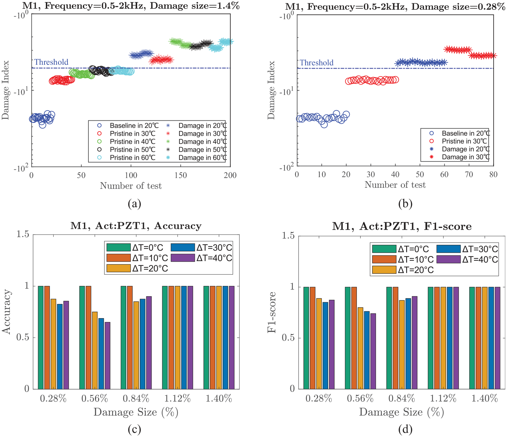
Results of M1 obtained by different conditions: (a) damage index obtained by M1 at different temperatures when damage size=1.4%, (b) damage index obtained by M1 at different temperatures when damage size=0.28%, (c)
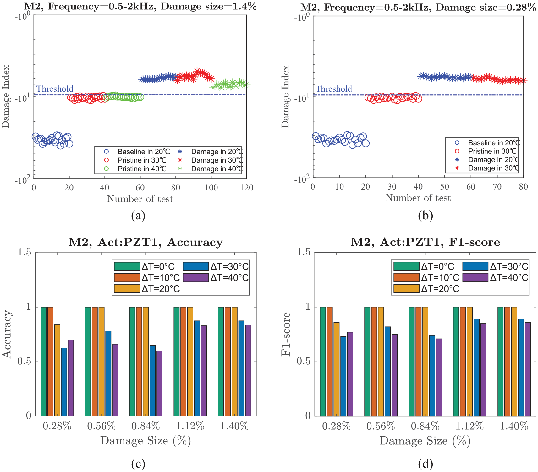
Results of M2 obtained by different conditions: (a) damage index obtained by M2 at different temperatures when damage size=1.4%, (b) damage index obtained by M2 at different temperatures when damage size=0.28%, (c)
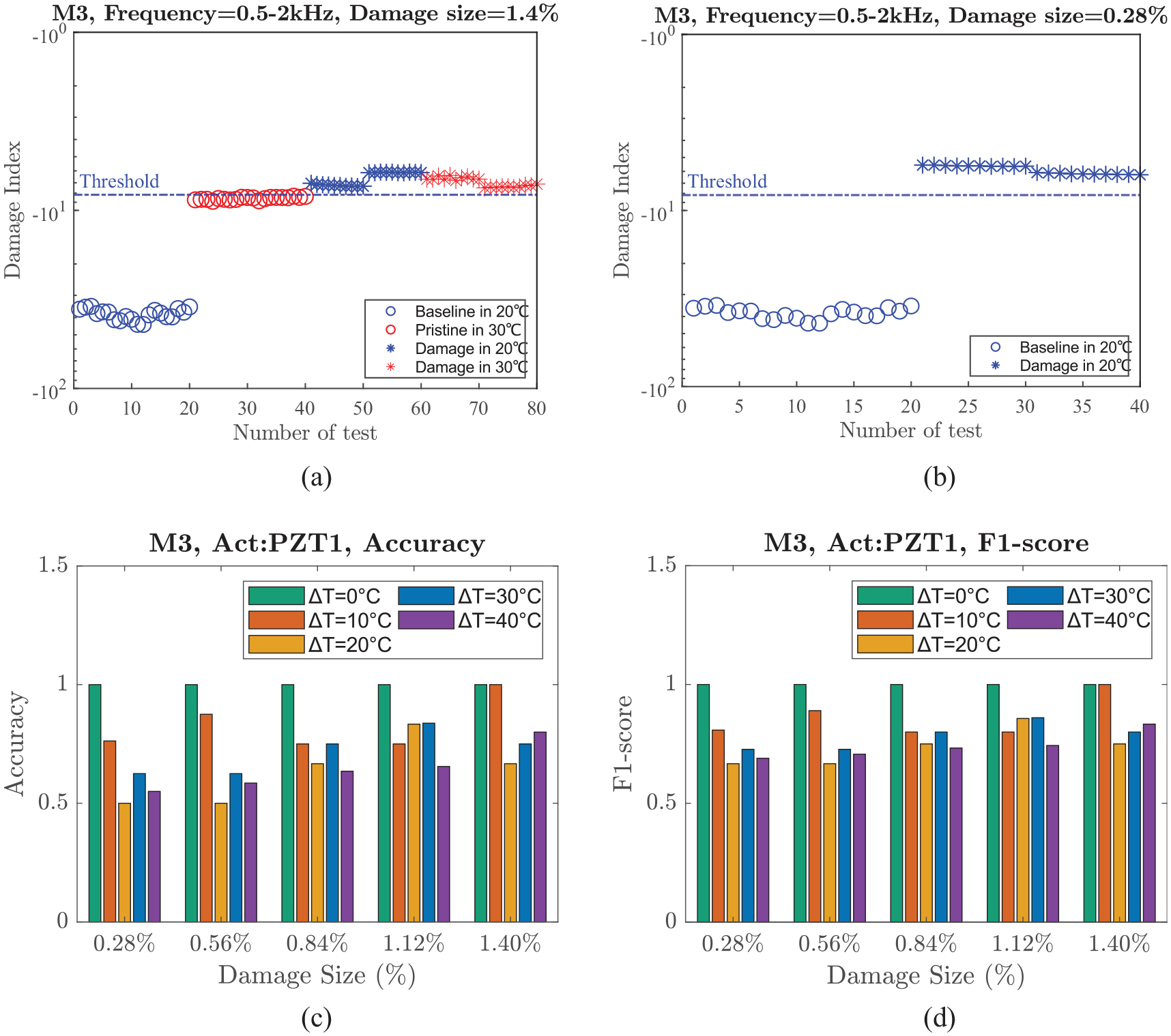
Results of M3 obtained by different conditions: (a) damage index obtained by M3 at different temperatures when damage size=1.4%, (b) damage index obtained by M3 at the same temperature when damage size=0.28%, (c)
Figure 8(a) shows the performance of the proposed method in damage detection on M1 under varying temperatures when the damage size is 1.4%. It is found that the method is capable of detecting the damage within the temperature difference of 40°C, and the threshold calculated based on
Figure 9 summarizes the results obtained from the analysis of composite plate M2. Figure 9(a) indicates the maximum effective working temperature difference for detecting the damage size 1.4% is 20°C, with the detection threshold calculated as −9.48 based on
The M3 plate is characterized as a curved composite plate that exhibits anisotropic behavior due to the orientation of the prepreg plies in the same direction. This feature imparts greater complexity to the guided wave propagation on the plate. The performance of the proposed method in detecting damage on M3 is presented in Figure 10 under different conditions. It is demonstrated that the proposed method can accurately detect damage size equivalent to 1.40% within and outside the sensor area under a temperature difference of
Uncertainty quantification
As discussed in the previous section, TFs are sensitive to damage and temperature within a specified threshold, which provides the possibility to detect damage within a temperature difference. However, TFs over the frequency band may also be affected by diverse experimental conditions, particularly the variation in sensor location. As such, another PZT is used as an actuator to evaluate the effect of sensor location. Figure 11 shows the configuration of the setup, where PZT 2 is used as an actuator, and the remaining three PZTs are used as sensors. TFs obtained by different actuator locations are reported in Figure 12.
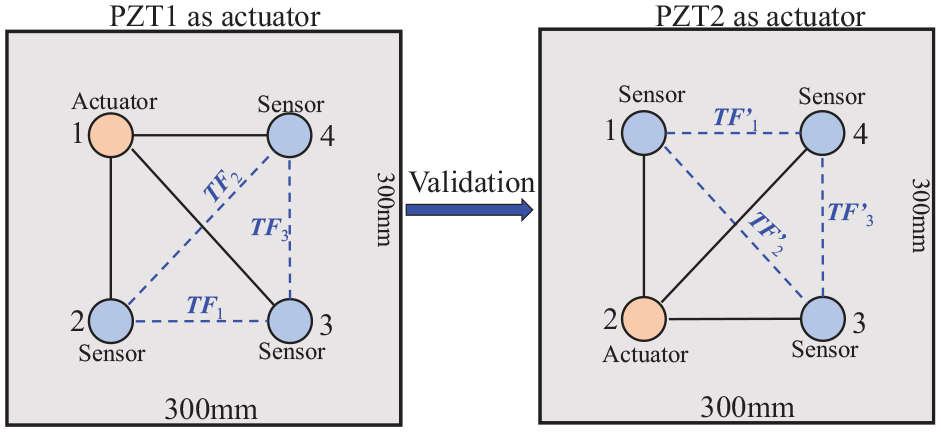
The configuration of different actuator locations.
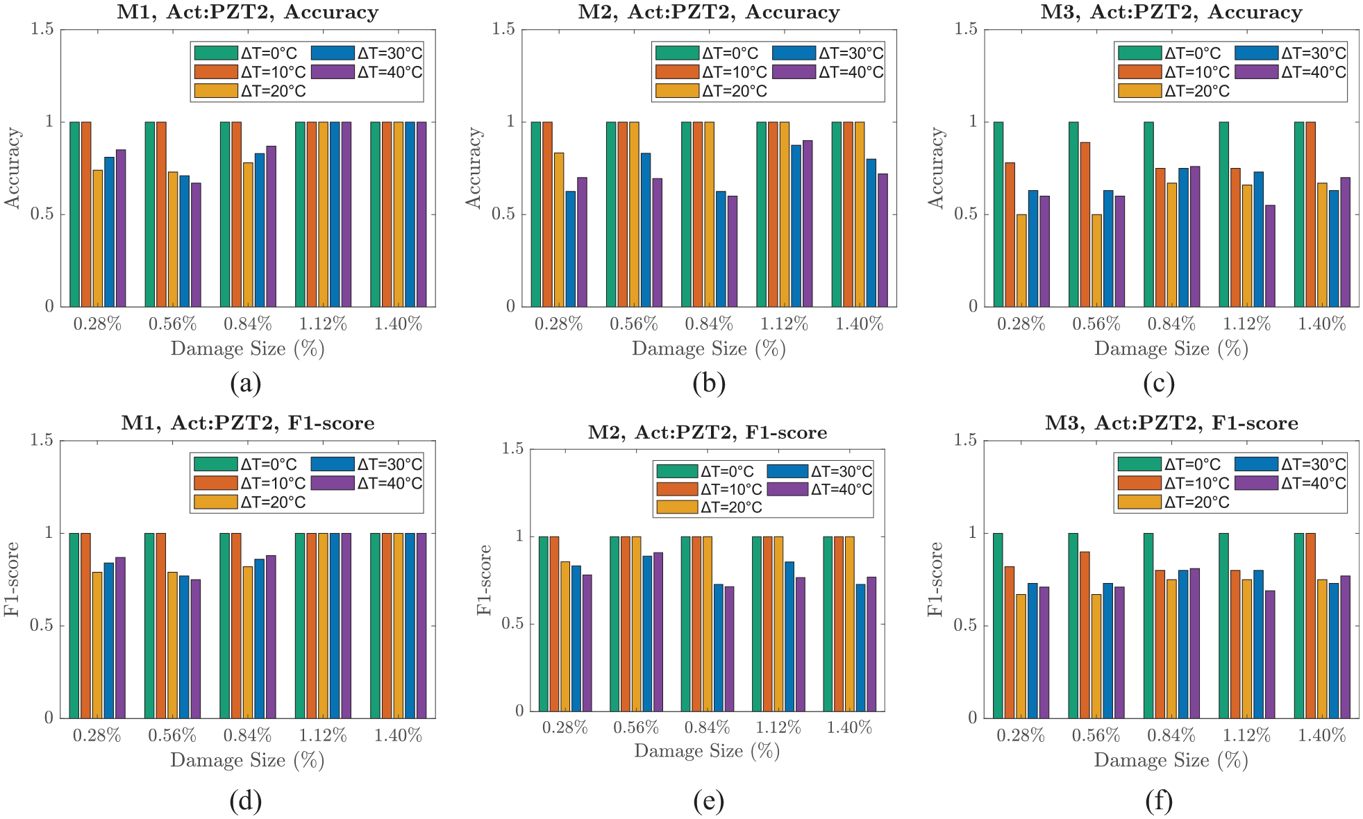
Figure 12 presents the detection results obtained from M1, M2, and M3 under different conditions, including different temperatures, damage locations, and sizes, using PZT 2 as the actuator. In Figure 12(a) and (d), when PZT2 is used as the actuator, the proposed method completely identifies both intact and damaged samples at all locations within and outside the sensing area over a temperature difference of 40°C, and the minimum damage size that the method can detect is 1.12%. In addition, when
Conclusion
In this research, a novel methodology combining GWSHM and modal analysis is proposed for damage detection on aluminum and two different composite plates under different temperature conditions without temperature compensation. TFs, representing the modal properties of the structures, were used as features to successfully distinguish damage-induced and temperature effects, followed by the outlier analysis to detect damage. The main conclusions of this research are highlighted as follows:
(-) For the isotropic Aluminum plate M1, the proposed method demonstrates remarkable effectiveness, achieving 100
(-) In the case of the quasi-isotropic composite plate M2, the proposed method can fully detect the damages of 1.4%, both inside and outside the sensing area, within a temperature difference of 20°C. Moreover, the minimum damage size that can be detected within this range is 0.56%.
(-) The anisotropic curved composite plate M3 exhibits promising results, with the proposed method successfully detecting damage equivalent to 1.40% both within and beyond the sensor area, even under a temperature difference of
(-) Consistent results from various sensor locations confirmed that the location does not influence the efficacy of this detection method, reinforcing the robustness of the proposed method.
In conclusion, the proposed hybrid SHM methodology presents a promising and robust tool for detecting structural damage under varying environmental conditions. This approach combines the high damage sensitivity of GWSHM with the temperature resilience of VSHM, addressing existing challenges in SHM. The innovative use of TFs as temperature-insensitive features (TIFs) minimizes reliance on extensive baseline datasets, requiring only a single baseline signal for damage detection over a wide temperature range. This methodology enhances detection reliability both within and beyond the immediate sensing area and extends applicability to structures with diverse geometries and environmental exposures, expanding SHM’s practical deployment in real-world scenarios. The multifunctional use of PZT transducers, which now support both guided wave and modal analyses, simplifies system complexity and reduces costs. Future work will focus on validating the method under more complex damage scenarios, such as delamination and progressive fatigue, and exploring the integration of TFs with additional SHM techniques to improve detection accuracy. In addition, ongoing efforts will aim to enhance the robustness of the proposed method across other environmental and operational variables beyond temperature, establishing a comprehensive framework for real-time SHM in aerospace and other critical applications.
Footnotes
Acknowledgements
This research did not receive any specific grant from funding agencies in the public, commercial, or not-for-profit sectors.
Declaration of conflicting interests
The author(s) declared no potential conflicts of interest with respect to the research, authorship, and/or publication of this article.
Funding
The author(s) received no financial support for the research, authorship, and/or publication of this article.