
Abstract
A method based on changes of electrical resistance was used to evaluate non-visible damage inflicted to multiscale hierarchical composites subjected to monotonic and cyclic bending loads. The composites comprise glass fiber weaves modified by carbon nanotubes in a vinyl ester matrix. Damage sensing is achieved by placing an array of electrodes close to the surfaces of four-point bending specimens and is correlated to strain fields measured by digital image correlation (DIC). The top (compressive) surface exhibited lower electrical resistance changes than the bottom (tensile) one. Spatial measurements of electrical resistance allowed identification of the most severely damaged zones, which coincided with those pinpointed by DIC. DIC also indicated an important presence of irreversible interlaminar shear strains accumulating close to the supports and/or loading introduction elements, which coincided with the location of delamination. The electrical technique allowed not only the detection of the onset of damage in the form of initial fiber breakage and matrix cracking, but also the detection of damage progression under cyclic loading and low-velocity impact.
Introduction
Fiber-reinforced polymer composites are widely used in aeronautical, naval, automotive, and wind energy applications. However, these materials exhibit complex failure mechanisms that are difficult to assess. Inspection methods, such as X-ray tomography1–3 and ultrasonic scanning,4–6 are very effective for detecting defects in composites but require removing the part from the structure and are not suited for real-time monitoring. Nondestructive methods, such as acoustic emissions3,7 and ultrasonic-guided waves (Lamb waves), 8 offer the advantages of in situ and real-time monitoring of the structures. However, those techniques require additional devices (sensors) attached to the analyzed structure and generally detect damage only at their immediate vicinity, thus limiting the sensing area. 9
An alternative to these methods is the one based on in situ monitoring the electrical response (mostly resistance or impedance) of the material.10,11 This technique uses the inherent electro-conductivity of the material, is noninvasive, and allows online monitoring of strain and damage.10–15 The technique is based on the change of the electrical resistance of the material upon application of load and infliction of composite damage (delamination, fiber breakage, and matrix cracking).14,16,17 Carbon fibers were first used to this aim,10,16,18–20 but their sensitivity was found to be very limited, and the technique is poorly sensitive to damage occurring in the matrix.16,18 As an alternative, carbon nanostructures, such as carbon nanotubes (CNTs) or graphenic sheets, have been used to modify either the fibers9,11,14,21–24 or the polymeric matrix20–22,24–26 of advanced polymer composites. Upon achieving a minimum electrical conductivity (just above electrical percolation) in the composite, the electrical conductivity (or resistance) of the material becomes sensitive to the inflicted damage.10,13,27 Given the small dimensions of carbon nanostructures, they can be deposited over micrometric engineering fibers without greatly modifying their mechanical properties, that is, they are considered noninvasive. Moreover, carbon nanostructures can reach small interstices and interfaces of the multiscale material, making the technique sensitive not only to fiber damage 14 but also to interfacial damage22,28 and other failure modes such as delamination.14,29 This technique has been employed to assess damage inflicted by tensile,21,30 bending,14,23,31 and impact loading,22,24,25 mostly under monotonic loading up to failure. The technique has also been proved effective for cycling loading,14,21,23,31 although reports on cycling loading are scarcer. However, in a real application of a composite structure, sequential and/or combined loading scenarios (such as cyclic bending followed by impact) are more common, and such loading cases have been very scarcely investigated.32,33 Furthermore, strain and damage detection has been mostly investigated and localized under the use of a pair of electrodes, whereas mapping efforts trying to pinpoint the location of damage are far more challenging.17,34–36 Such mapping efforts include techniques like the electrical impedance tomography and electrical resistance tomography. These methods generate a full field of the conductivity in the composites that could be related with the damaged zones. However, tomographic techniques require the implementation of complex algorithms and calibration parameters, adding more steps to the identification of damage.17,34,36
Therefore, this study investigates the electrical response of multiscale composites comprising CNT-modified glass fibers and a thermosetting polymer under four-point bending. Three loading scenarios are investigated, viz. monotonic loading up to failure, cyclic bending, and cyclic bending interjected by two low-velocity impacts. Onset as well as damage tolerance is investigated. A grid of electrodes is used to map the location (onset and propagation) of damage in the flexural coupons. The set of real-time electrical measurements are compared against full-field strains measured by the digital image correlation (DIC) technique, allowing to build correlations with full strain maps of elastic (recoverable) strains and accumulated damage.
Materials and methods
Materials
For manufacturing of the laminated composites, a Derakane Momentum 470-300 vinyl ester resin (VER) was used as polymer matrix. Cobalt naphthenate (CoNap, active cobalt concentration of 6 vol.%) was used as promoter of the polymerization, whereas methyl ethyl ketone peroxide (MEKP, active oxygen concentration of 9 vol.%) was used as initiator. All components (VER, CoNap, and MEKP) were acquired from Plastiformas de México (Mexico City, Mexico). E-glass fiber (GF) in a balanced (0°/90°) plain weave configuration was used as mechanical reinforcement. The GF weave was acquired from “Poliformas Plásticas” (Mérida, Mexico). Commercial multiwall CNTs with outer diameters of 30–50 nm, lengths of 1–6 µm, and purity >95% were used as electrical fillers (Cheaptubes Inc., Grafton, VT, USA).
Manufacturing of hierarchical composites
CNTs were firstly oxidized to generate OH and COOH functional groups that improve their bonding with the sizing of the GF weave. 37 For this, the CNTs were dispersed in a solution of sulfuric (3.0 M) and nitric (3.0 M) acids using an ultrasonic bath (42 kHz, 70 W) for 2 h and rinsed with distilled water to neutralize the acidic solution. 38 Then, 60 mg of oxidized CNTs were deposited onto the surface of the GF weave with dimensions of 150 × 40 mm by the dipping method. The GF weave was dipped in 200 ml of a CNT/distillated water solution (0.3 mg/ml), and this solution was dispersed using an ultrasonic horn (70 kHz, 225 W) for 90 min, with equally spaced periods of 30 s of operation and rest. The GF weave was taken out of the CNT/distilled water solution and dried in a convection oven at 100°C for 4 h. Only two GF weaves were modified with CNTs, viz. the top and bottom ones. The weight concentration of the CNTs over each GF weave is approximately 0.5 wt.%. This concentration may be considered as an upper bound since it does not consider the CNT losses during handling. The electrical resistance of the CNT-modified GF weaves at different locations over the weave was within the 103–104 Ω range, showing adequate homogeneity. A 125 × 25 mm section of the CNT/GF weave was cut to use as sensing layer for the specimen. Each four-point bending specimen comprised nine layers of GF weaves with dimensions of 125 × 25 mm, but only two of them were CNT-modified layers, viz. the top and bottom layers. The other seven layers were as-received GF weaves. The GF weaves were stacked inside a silicone mold, and a mixture of VER with CoNap and MEKP (both at 0.5 wt.%) was poured between the plies, hand-pressing each GF to avoid fiber waviness. Subsequently, this silicone mold was bag-sealed and placed under vacuum for 24 h at room temperature, to promote compaction and homogeneity among specimens. Post-curing was carried out for 2 h at 120°C in a convection oven. The nominal thickness of the laminated specimens was 8 mm (0.89 mm thick each layer). In each coupon, an array of 16 electrodes (eight electrodes per surface) was instrumented to acquire the electrical signal. The electrodes consisted in 30 AWG copper wires attached to the CNT-modified GF plies with conductive paint (Bare Conductive, London, England). The specimen dimensions and distribution of electrodes are shown in Figure 1.
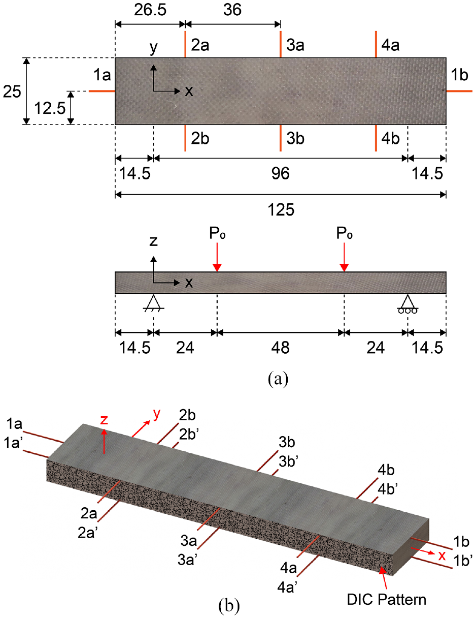
Four-point bending specimens: (a) dimensions (in mm) and distribution of supports and load application points and (b) distribution and identification labels of electrodes.
Flexural testing
Mechanical and electromechanical responses of the laminated composites subjected to four-point bending tests were obtained using three loading programs, that is, quasi-static monotonic loading until failure, sinusoidal cyclic loading for 5000 cycles, and sinusoidal cyclic loading with two interjected impacts. The monotonic tests were carried out using a universal testing machine Shimadzu AG-I equipped with a 5 kN load cell and a crosshead displacement of 1 mm/min. These tests considered a span length (Lg) of 96 mm and a distance between loading noses of 48 mm (Figure 1(a)). The cyclic loading tests were performed in an MTS Landmark 370 servo-hydraulic universal testing machine equipped with a 10-kN load cell. The tests were performed using similar specimens to those for the monotonic load (Figure 1(a)) but tested with a cyclic sinusoidal load of 0.5 Hz frequency (2 s/cycle) during 5000 loading–unloading cycles. The tests were force-controlled and the applied sinusoidally force oscillated between a peak load of 1845 N and a minimum load of zero. The peak load used in the cyclic tests corresponds to 50 % of the average failure load measured during the monotonic loading test program. To promote damage accumulation emulating a realistic scenario, low-velocity impact loading was inflicted to the specimens alternating with the cyclic loads. Impact loading was achieved by using the free fall dart technique at cycles 1000 and 2000. The dart (hemispherical tip of 12 mm diameter and mass of 2 kg) was falling from a height of 70 cm and rendered a single impact of 11.8 J. For this last set of specimens, the bending tests were stopped at 1000 and 2000 cycles, the specimen was taken out of the flexural test rig, impacted, and brought back to the bending test rig for continuation of the cyclic loading. Three specimens were tested for the monotonic test, two for the cyclic, and two for the cyclic combined with impact, and representative results are shown in Sections “Damage detection in hierarchical composites tested under cyclic bending” and “Damage detection in hierarchical composites tested under cyclic bending alternated with low-velocity impacts.”
During the bending tests, the strain fields were obtained using a 5-Megapixel stereo camera system GOM Aramis 5 M LT (Optical Measuring Techniques, Braunschweig, Germany) DIC equipment, and the commercial software ARAMIS v6.3.1. Loading and displacement data from the testing machine were recorded by the DIC equipment to correlate the measured strain fields with the strain–stress curve. From this technique, the longitudinal (εx), through-thickness (εz), and transverse shear (γxz) strain fields were acquired from all quasi-static and cyclic loading tests. This is because each strain field relates to a different failure mechanism in laminated composites. Longitudinal strains (εx), correlated to fiber failure and matrix cracking, while the through-thickness (εz) and transverse shear (γxz) strain fields are associated to the presence and growth of delaminations. The DIC images were acquired at a frequency of 1 Hz (1 image/s) for the monotonic tests. For the cyclic tests, DIC images were collected during select periods of time, that is, at predetermined cycles (every 1000 cycles). DIC images were taken at high frequency (4 images/s) during 30 s (15 cycles) in order to better capture the loading and unloading process. For the impacted specimens, additional DIC images were acquired after each impact (cycles 1001 and 2001).
Electrical damage assessment
A set of electrical resistance data of the specimens was acquired during the bending tests using the array of electrodes shown in Figure 1(b). Eight electrodes were instrumented at the top and bottom layers of the laminated composites, two longitudinal ones (named 1a and 1b for the top surface), and six transverse ones (named 2a, 2b, 3a, 3b, 4a, and 4b). 2a, 3a, and 4a are at the front (DIC speckled) edge of the specimen, whereas 2b, 3b, and 4b are at the back edge. The longitudinal electrodes are placed along the x-axis, at the mid-width of the coupon. Excepting electrodes with number “1,” electrodes with the same number (e.g., 2a and 2b) share the same x-coordinate, whereas electrodes with the same letter (e.g., 2a and 3a) share the same y-coordinate. Similar labeling was used for the bottom surface (the one subjected to tension), but a prime symbol (′) was added for distinction.
The electrical measurements were carried out using a Keysight 34980A multifunction switch equipment and two Agilent modules 34921A and 34923A. Especial connections were designed to organize and manage the electrical data. The array of electrodes was organized in a frame containing 16 copper joints (eight for each surface) and connected to a printed circuit board (PCB), especially designed for ease of handling the wires and data collection. This PCB was connected to the terminal block of the Keysight 34980A multifunction switch equipment.
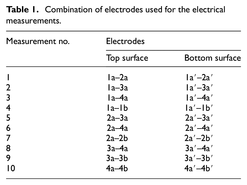
Electrical resistance measurements were acquired using the combinations of pairs of electrodes presented in Table 1. This yielded 10 measurements per surface of the coupons (20 measurements in total), according to the distribution of electrodes presented in Figure 1(b). The large number of measurements collected assists in increasing the spatial resolution of the electrical method. The equipment switches each electrical resistance measurement every 50 ms so all the set of electrodes was measured every 1 s.
Combination of electrodes used for the electrical measurements.
To synchronize the acquired electrical and mechanical data, the analog voltage signals corresponding to load and displacement of the universal testing machine were acquired with the same terminal block of the 34923A module multifunctional switch equipment. The measurements were performed with a rate of 1 scan/s, where each scan consists in the acquisition of 20 electrical resistance values and 2 voltage data (22 data/s). The initial values of electrical resistance were slightly different between specimens, but in all cases were between 103 and 104 Ω. The change of electrical resistance was normalized with the corresponding initial value of R (i.e., at zero strain).
Optical and scanning electron microscopy
For the evaluation of damage and failure mechanisms, optical images and scanning electronic micrographs were acquired at selected zones. Optical images of the complete specimens were acquired with a photographic camera (CCD 48 Mpx Samsung GW1 sensor), and close-ups of the damaged regions were taken with a digital microscope of 2 Mpx resolution. Scanning electron microscopy (SEM) images with magnifications varying from 30× up to 1000× were acquired on samples covered with a thin layer (∼4 nm) of gold by using a JEOL JSM-6360LV SEM. SEM images were acquired from the outer surface of the composites, to avoid alterations by the effect of cutting. SEM images corresponded to 1 × 1 cm cut samples in the zone between the loading noses and the supports of the bending fixture, and at the center region of the impacted coupons.
Results
Damage detection in hierarchical composites tested under monotonic bending until failure
The results of damage monitoring in the laminated composites by means of the electrical resistance method for a monotonic bending test until failure are shown in Figure 2. Figure 2(a) corresponds to the electrical resistance measurements on the top (upper figure, surface under compression) and bottom surfaces (lower figure, surface under tension). Figure 2(b)–(d) corresponds to the DIC strain fields obtained at different strain/stress levels during testing up to failure. Letters “A” to “E” at the left side of such figures (stages) correspond to the strain levels indicated in Figure 2(a). Letter “A” corresponds to 30% of the failure stress, whereas “E” corresponds to a stress very close to the failure stress. The numbering code at the box placed at the right side corresponds to the pairs of electrodes defined in Figure 1 and Table 1. Outer vertical dashed lines in Figure 2(b)–(d) are reference lines, which correspond to the location of the left (LS) and right (RS) supports, whereas the vertical inner lines correspond to the location of the left and right loading noses (LN and RN, respectively).
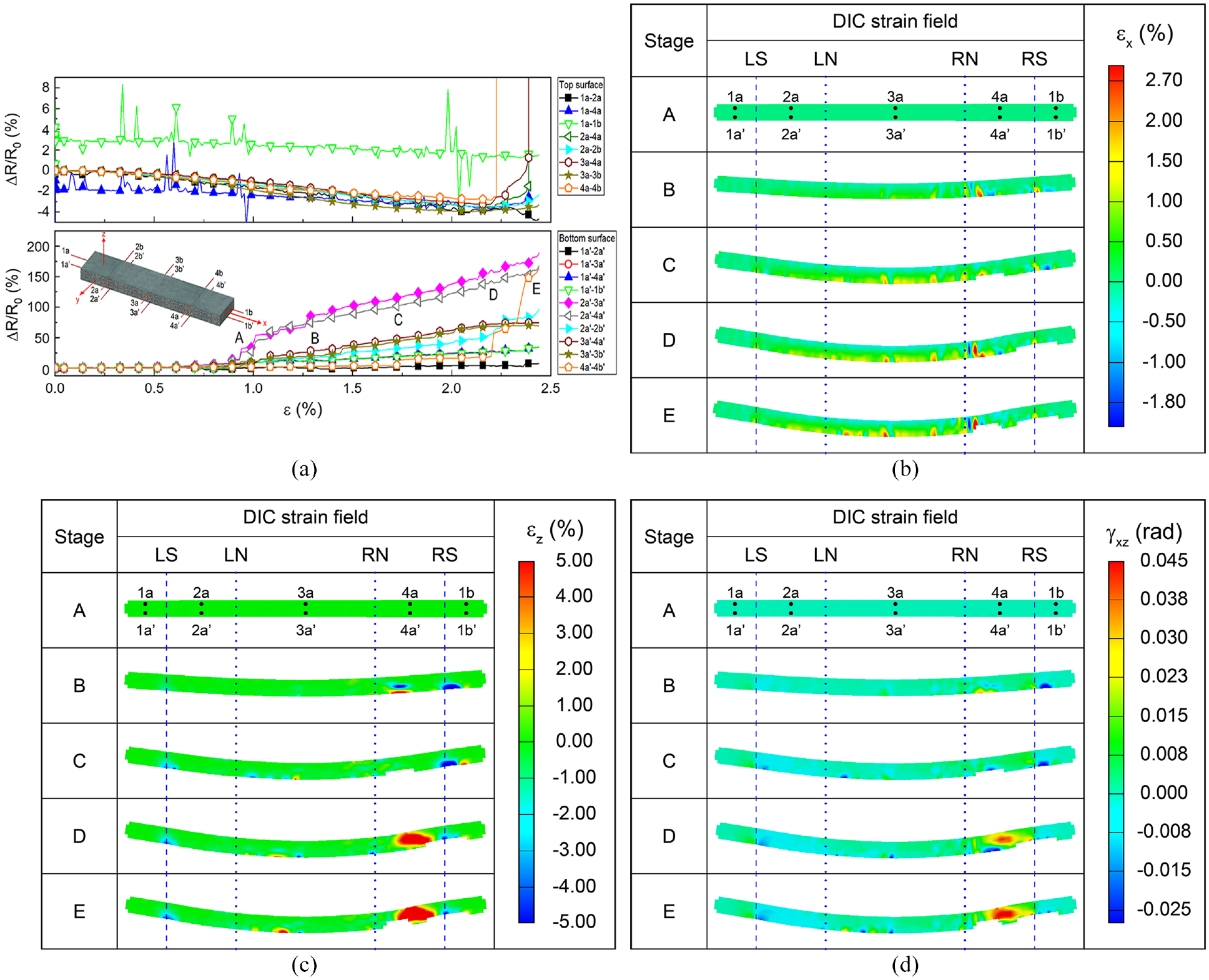
Damage assessment during the monotonic bending test of a CNT-GF/VER specimen: (a) electrical response in compression (top) and tension (bottom) surfaces; (b) to (d) correspond to associated DIC strain fields. (b) εx, (c) εz, and (d) γxz.
At the upper (compression) surface the electrical resistance linearly decreased for εx < 1.25%, which is due to the piezoresistivity of the material subjected to compressive strain. 14 A few scattered peaks of ΔR/R0 suggest the occurrence of randomly isolated microcracking, which do not significantly affect the load bearing capacity at this strain/load level. For 1.25% < εx < 2.0%, the slope of the curve tends to level off due to the presence of two competing mechanisms. On one hand, the compressive strain causes the decrease of the distance between the CNTs on the glass fabric, yielding a small reduction of the electrical resistance.14,39 On the other hand, the incipient generation and accumulation of damage causes disruptions of the electrical paths formed by the CNTs, which increases the electrical resistance. This counteracts the effect produced by the strain-induced piezoresistivity. It is known that fiber breakage in laminated composites occurs in a statistical fashion and typically follows the Weibull distribution, 40 meaning that a few fibers may break at early loading, without significantly affecting the global load bearing capacity of the specimens. Similarly, early isolated matrix microcracks do not significantly affect the global mechanical response of a fiber-reinforced specimen, until such cracks coalesce and form larger cracks which trigger delamination.41,42 For εx > 2.0%, the slope of the ΔR/R0 curves changes to slightly positive values, indicating that the electrical effects caused by damage overcome the small piezoresistive response, yielding an effective increase of ΔR/R0. Finally, for εx ∼ 2.25%, abrupt peaks in ΔR/R0 are observed, especially for the electrodes 1a–4a, 2a–4a, 3a–4a, and 4a–4b. This is related to the presence of damage in the vicinity of the electrode 4a, that is, in a zone at the right part of the coupon. The appearance of damage predominantly in this region can be related to unavoidable manufacturing imperfections. Initial imperfections occur randomly within the laminated composites, disrupting the symmetry of the strain fields, and producing strain concentrations that may even trigger failure.
The identification of the zone of larger damage is strongly correlated to the DIC strain fields in Figure 2(b)–(d). As seen from Figure 2(b), the longitudinal strain field (εx) presents strain gradients in the vicinity of electrode 4a since the stress level indicated by the letter B (40% of the flexural strength), and the field intensity grow in that location with the applied load (C to E). Nevertheless, according to the DIC, the presence of damage in this region is more evident for the normal transverse (εz, Figure 2(c)) and for the transverse shear (γxz, Figure 2(d)) strain fields. The higher concentration of gradients detected is caused by the shear stresses in the region between the outer support and the inner loading nose, which is expected to trigger delamination.14,41 A similar situation occurs for the bottom surface (the one subjected to tensile stresses), but the changes in ΔR/R0 are considerably larger. Since both piezoresistivity and damage generation yield positive ΔR/R0 at this surface, sign transitions are not observed in this case. For the bottom surface, a small linearly positive ΔR/R0 (hindered by the large scale of the vertical axis) is seen for 0% < εx < 0.75%. For εx > 0.75%, the ΔR/R0 curves split apart, indicating most abrupt changes for the pair of electrodes 2a′-3a′ and 2a′-4a′. Both electrodes display large ΔR/R0, reaching up to ∼150% (1.5 times R0) close to failure. This large and sudden increase of electrical resistance is associated with the disruption of the CNT conductive pathways when the specimen is subjected to large tensile stresses. 23 The higher electrical sensitivity of the bottom surface is attributed to the fact that tensile stresses tend to cause CNT-network disruption, which yields larger changes of electrical resistance than the re-aggrupation by compression. Furthermore, at the compression side, the two governing electrical mechanisms (network disruption by damage and piezoresistivity) counteract. 39
As for the top surface, the region that presented the highest changes of ΔR/R0 (near electrode 4a′ at the bottom surface) coincide with the regions of largest strain gradients obtained by DIC. At the vicinity of the left support (4a′) on the bottom surface, negative γxz strain fields are observed, suggesting that the CNTs deposited on the fibers’ surface can monitor the state of strain/stress in the material, including transverse shear stresses that affect the fiber–matrix interface and are known to trigger delamination. Notice that some pairs of electrodes (e.g., 2a–3a) present high electrical resistance changes, but not the highest DIC strain gradients. This is likely due to the nature of the DIC technique, which only measures surface strain in the specimens. On the other hand, the electrical technique is able to sense internal (volumetric) damage.
Damage detection in hierarchical composites tested under cyclic bending
The results of the electromechanical tests of a representative specimen subjected to cyclic four-point bending (without impact) are shown in Figure 3. The electrical resistance measurements at the top surface (Figure 3(a), upper figure) oscillated between positive and negative values of ΔR/R0, with negative ones lower than 1% and positive ones lower than 10%.
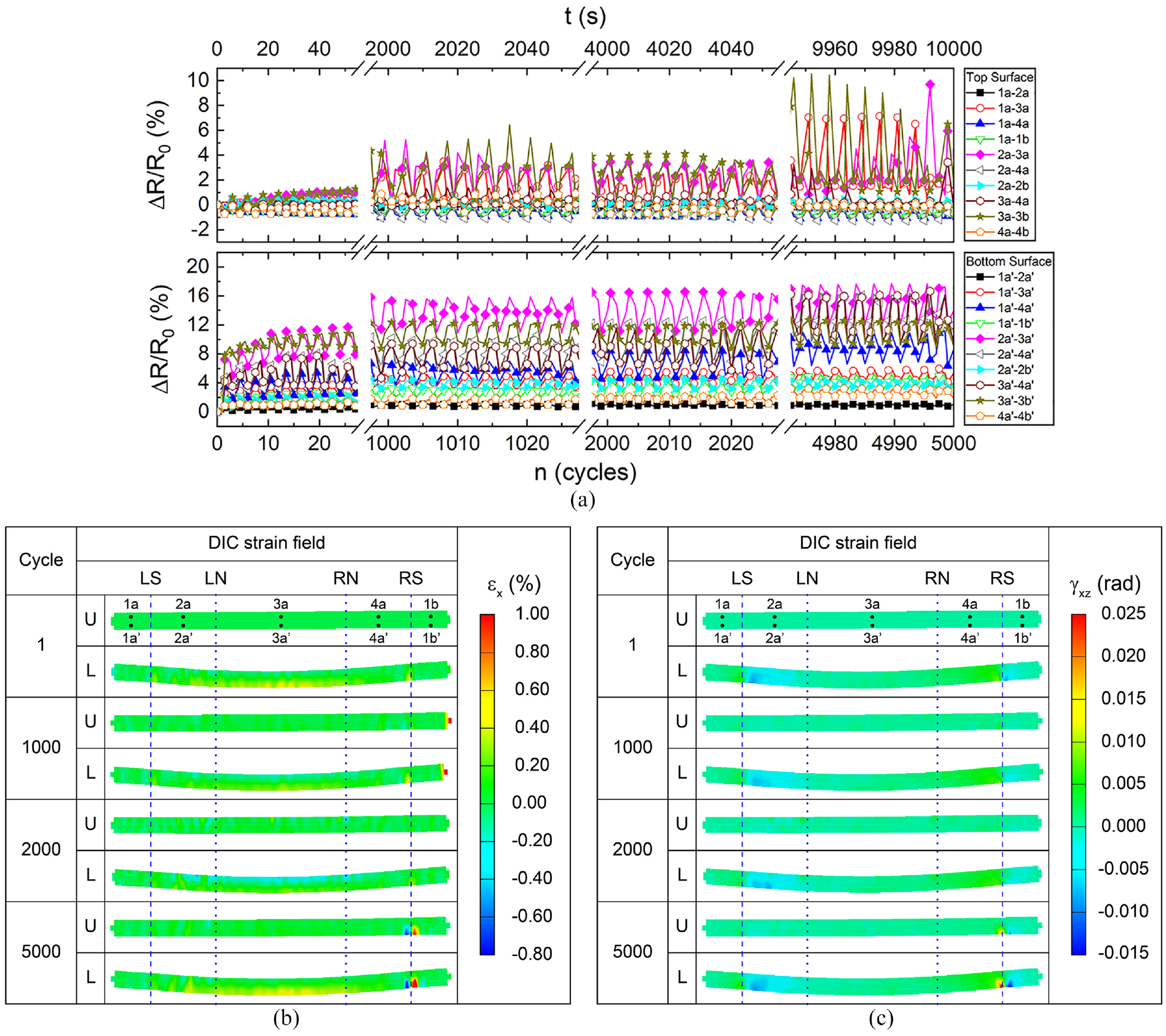
Damage assessment of a hierarchical composite specimen during cyclic bending tests without impact. U and L represent the unloading and loading stages, respectively: (a) electrical response in the compression (top) and tension (bottom) surfaces; (b) and (c) correspond to DIC strain fields. (b) εx and (c) γxz.
On this surface, the (small) negative changes are attributed to the piezoresistivity response of the material. Values of ΔR/R0 close to −1% are within the range of those observed in the monotonic tests until failure, ascribed to piezoresistivity (Figure 3(a)). When the specimen bends, the top surface is under compression strain and the distance between CNTs conforming the percolated network diminish, reducing the global electrical resistance of the laminate. This piezoresistive effect is reversible when the load is brought back to zero during the cyclic tests. The pairs of electrodes 1a–3a, 2a–3a, and 3a–3b exhibited maximum positives changes of ΔR/R0 (up to 10%), which increased gradually with the number of cycles. These positive ΔR/R0 are caused by disruption of the electrical network of CNTs due to the presence of a combined state of stresses that yield matrix microcracking and fiber breakage during the bending test. 15 As for the location, the fact that the largest peaks of ΔR/R0 occur at electrodes 1a–3a, 2a–3a, and 3a–3b is associated with damage originated in the central region of the specimen subjected to the maximum bending moment (see DIC maps for εx in Figure 3(b)). After the unloading stage (U) of each cycle, it is observed that the values of ΔR/R0 go beyond zero (ΔR/R0 < 0), indicating permanent changes in the electrically conductive network after a significant number of cyclic loadings. These permanent changes at the compression side can be related to local crushing and local buckling of the fibers within the composite, which cause local progressive damage and accumulation at the compressive side. Notice in Figure 3(b) that, at and after n = 2000, damage is accumulated at the central part of the specimen even upon unloading (U).
As for the monotonic loading tests, the bottom (tension) surface exhibited only positive changes of ΔR/R0, ranging between 0 and 15%. The oscillatory character of ΔR/R0 matches that of the cyclic loading, and several electrodes presented positive residual ΔR/R0 even at the unloading stage. The residual (non-zero) ΔR/R0 when the specimen is fully unloaded indicates permanent changes in the electrically conductive network that are associated to accumulation of permanent damage. Furthermore, their magnitude increases as the number of cycles increases, which is conspicuous evidence that the technique is sensitive to damage that accumulates irreversibly during the loading cycles. On this surface, the electrical resistance measurements of the pairs 2a′–3a′, 3a′–3b′, and 2a′–4a′ exhibited the largest changes of ΔR/R0, pinpointing the location of most severe damage. As seen from Figure 1(b), the pair 3a′–3b′ corresponds to the central region of the specimen, where the maximum bending moment occurs. This holds a strong correlation with the DIC strain maps of εx shown in Figure 3(b). The locations 2a′ and 4a′ correspond to locations between the supports and load introduction points (see Figure 1), and the strain fields of γxz (Figure 3(c)) indicate large strain gradients in the proximity of those locations. γxz are well-known for triggering delamination. 41 Thus, the electrical technique is not only able to sense fiber breakage and matrix cracking but also interlaminar failure phenomena such as delamination.
Damage detection in hierarchical composites tested under cyclic bending alternated with low-velocity impacts
Figure 4 presents the results of the electromechanical cyclic tests combined with two low-velocity impact events and the associated DIC strain fields of a hierarchical composite specimen. The low-velocity impacts were performed right after cycle n = 1000 and 2000. Thus, the impact took place between cycle 1000 and 1001 and then again between cycle 2000 and 2001. DIC maps for both cases, before and after the impact, are included in this case.
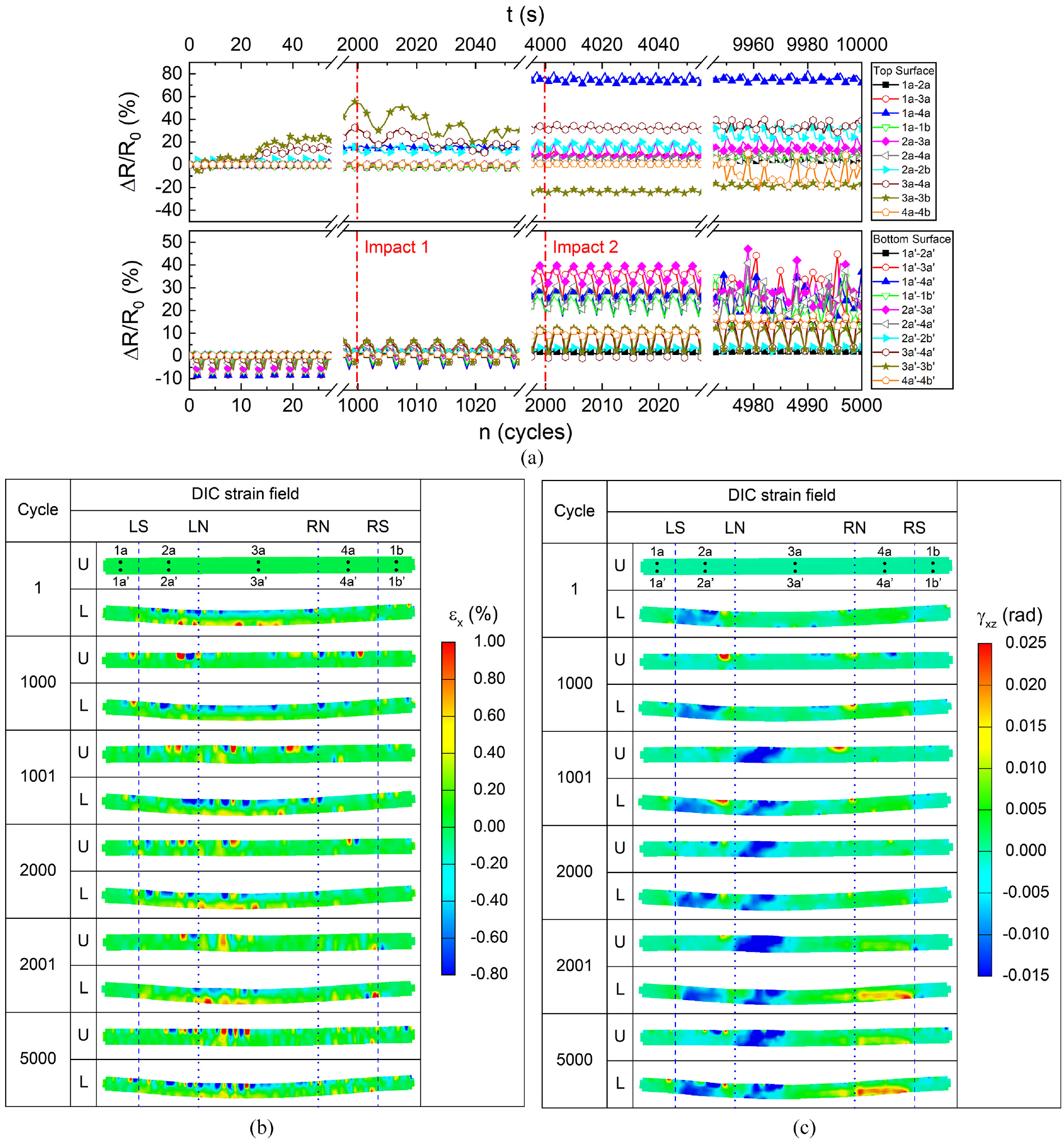
Damage assessment of a hierarchical laminated specimen during cyclic bending tests alternated with low-velocity impacts at n = 1000 and 2000: (a) electrical response at the compression (top) and tension (bottom) surfaces, and (b) and (c) correspond to DIC strain fields; (b) εx and (c) γxz.
All pairs of electrodes at the top surface (Figure 4(a), upper figure) exhibited values of ΔR/R0 lower than ±10% during the first cycles, similar to the non-impacted specimens (Figure 3(a)). After the first impact (n = 1000), the amplitude of the ΔR/R0 peaks, significantly increasing in some pairs of electrodes such as 3a–4a and 3a–3b, which presented absolute changes up to ±35%. In addition, the magnitude of ΔR/R0 does not go back to zero upon unloading, for any of the electrodes. This means that damage is more severe and more spatially spread after the impact event and accumulates with the cycle number and impact number. The central location 3a–3b is close, to the impacted region, and thus exhibited a significant residual ΔR/R0, indicating permanent damage in this zone. The presence of damage was also observed with the DIC strain fields, which showed higher gradients of εx, εz, and γxz close to the electrodes 3a–3b.
After the second impact (n = 2000), a higher number of electrodes (2a–3a, 2a–2b, 3a–4a, 3a–3b, and 4a–4b) show large peaks of ΔR/R0, indicating that the extension of damage was over the whole bending coupon, affecting a large part of the electrodes. The fact that large gradients γxz were observable by DIC suggest that microcracks and delaminations generated by the impact disrupted the percolated network of CNTs within the material, affecting its global electrical resistance, with an increase in the severity of the damage after each impact. 43 By the end of the test (n = 4990–5000), the accumulated damage was so large (see Figure 4(c)) that the ΔR/R0 response comprised erratic peaks of large amplitude, indicating a large destruction of the CNT conductive paths due to the presence of large accumulated cyclic and impact damage. The gradients of strain that correspond to the impacts are displaced from the center of the coupon (the impact was at the center), indicating that the highest damage caused by the impact was not exactly under the surface in contact with the impactor dart.
On the other hand, the bottom surface (Figure 4(a), second plot) presented values of ΔR/R0 lower than 10% during the first cycles in all the pairs of electrodes. After the first impact (n = 1000), the electrodes 1a′–3a′ and 2a′-3a′ showed the highest values of ΔR/R0 with changes of ∼40% when the coupon is the loading section of the cyclic program. The pairs of electrodes 1a′–4a′, 1a′–1b′, and 2a′–4a′ also suffered significative changes of electrical resistance with ΔR/R0∼20% at the unloading and 30% at the loading stage. By their location, the changes of electrical resistance can be associated with the presence of damage between electrodes 2a′ and 3a′ since all the mentioned measurements cross over this location. From DIC results, γxz shows that the region with higher strain caused by the impact was generated precisely between electrodes 2a′ and 3a′.
Microscopic evaluation of damage
In addition to the DIC damage assessment, a post-mortem analysis of the failure mechanisms of the tested specimens was conducted by means of optical and SEMs. Figure 5 presents optical microscopy images of a selected specimen tested monotonically up to failure (Figure 5(a)) and one tested under cyclic bending with impact (Figure 5(b)). Similar failure mechanisms were observed for specimens tested under cyclic loading without impact, and thus the results are not shown. Each figure contains three views of the specimen (top, lateral, and bottom) with close-ups around the damaged zones, labeled “Close-up 1” and “Close up-2.”
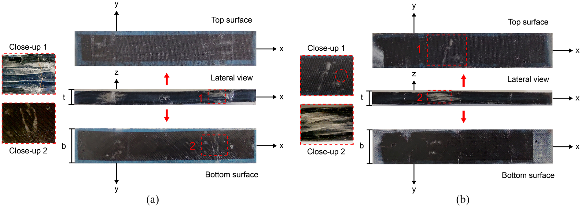
Optical microscopy images of the tested specimens: (a) after monotonic loading until failure and (b) after 5000 bending cycles at 50% of the strength, alternating with two impacts.
According to the conventional mechanics of materials theory of the four-point bending test for linear-elastic materials, the bending moment is maximum at the span-center (between the loading elements), and shear stresses are maximum at the region between the supports and loading noses and vanish in the center. However, this theory does not account for stress concentrations at the vicinity of the support and loading elements, which are identified by the DIC maps. It is also known that delaminations are triggered by transverse normal and transverse shear stresses/strains. From the DIC images of Figure 4(b) and (c), it is observed that the specimens subjected to monotonic loading until failure presented large gradients of εz and γxz at the vicinity of the supports and loading noses, making such zones susceptible to delaminations. This is confirmed from Figure 5(a), where the presence of delaminations is conspicuously identified. Matrix cracking and fiber rupture were also visible at the top and bottom surface, as well as in the close-ups. The central region of the specimen was prone to failure by fiber breakage, in the longitudinal direction, driven by εx. It has been argued that damage in fiber-reinforced laminated composites subjected to bending starts with debonding between fiber and matrix, generating microcracks. Those microcracks grow and coalesce (especially at the tensile side) to form transverse cracks that propagate in the span of the specimen. 42 Catastrophic failure occurs when the microcracks merge to form continuous macroscopic delaminations like those observed in the close-up 2 in Figure 5(a).
Similar failure mechanisms were observed in specimens subjected to cyclic and impact loading, Figure 4(b), although the failure mechanisms were less evident in the neighborhood of the supports and loading noses. These specimens also presented a small indentation in the area hit by the impactor dart. It is known that low-velocity impacts generate shear stresses that promote the generation of delaminations in the interphases among the layers close to the impacted surface, whereas in the opposite surface, the tensile stresses cause fiber breakage.1,44 At the same time, this zone could be correlated with the highest changes of ΔR/R0, correlating the presence of damage in the impacted region with DIC.
Additionally, SEM images were acquired from x–z plane (Figure 6) of the tested specimens at the region between a support and a loading nose in specimens loaded monotonically until failure (Figure 6). In this way, the procedure for cutting the SEM samples from the bending specimen does not incur in any damage to the imaged region. Matrix cracking is evident in Figure 6, showing cracks running along the longitudinal (x) direction of the composite. Broken fibers are observed coming out from the cracks. Catastrophic failure is evidenced by cracks, which move through the thickness of the specimen and over the fiber, yielding delamination.
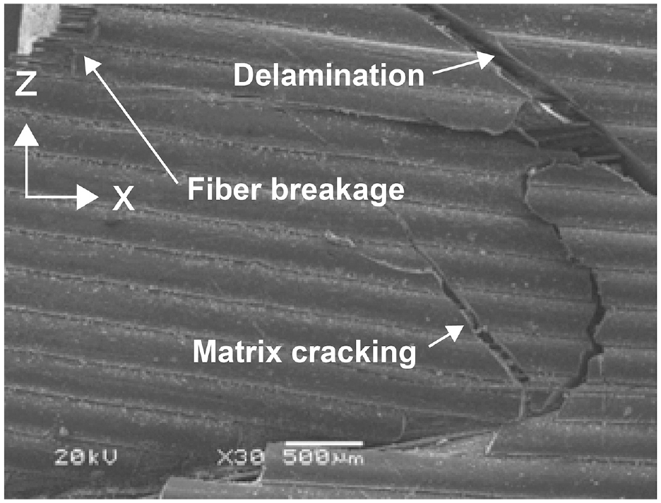
SEM of hierarchical specimen. Image shows a sample that was cut through the y-direction (Figure 1) leaving the lateral side (xz plane) exposed and intact.
Conclusions
CNT-modified glass fiber/vinyl ester laminates were investigated using an array of electrodes to detect damage caused by monotonic and cyclic bending alternated with low-velocity impacts. When tested up to failure, the fractional change of electrical resistance (ΔR/R0) at both surfaces was initially driven by piezoresistance, but after 1% of longitudinal strain, incipient damage was indicated by the electrical technique. Further damage was evidenced by abrupt peaks in ΔR/R0 and large nonlinear changes of electrical resistance, which reached up to ΔR/R0 ∼ 150% at the tensile side. The tensile side showed higher changes of electrical resistance upon loading, indicating higher sensitivity. The highest changes of electrical resistance corresponded to the mid-span zone and zones in the vicinity of the supports (between the supports and loading nose) showing a very strong correlation with the strain concentrations zones determined by DIC. In agreement with the electrical measurements, DIC indicated large strain gradients and accumulation of damage at the mid-span zone of the specimen, dominated by the largest bending moment (largest εx). Damage accumulation was also identified by both independent techniques at the zones between the supports and loading noses, where the normal through-thickness (εz) and interlaminar shear (γxz) strains are maximum. Specimens tested under cyclic loading exhibited an oscillatory response matching the cyclic loading. For a large number of cycles (>1000), the amplitude of the peaks grow with the number of cycles, indicating that the technique is sensitive not only to damage onset but also can assess accumulation of damage. Furthermore, upon permanent damage indicated by DIC, the electrical response does not return to zero upon unloading the specimen. If such cyclic loading program is alternated with low-velocity impacts, the electrical response shifts toward peaks of higher amplitude, and the number of electrodes displaying large values of ΔR/R0 significantly increases. This is an indication that the damage intensity and the spatial spread of damage caused by the impact is properly captured by the electrical response. Overall, the electrical technique showed high sensitivity to damage not only for longitudinal strains/stresses but most importantly in regions where transverse (normal and shear) strains show larger gradients, indicating high sensitivity to delamination. The highest ΔR/R0 values are conspicuously correlated to the highest strain gradients found by DIC, indicating that this array of electrodes can locate the zones that are more prone to failure and can follow the progression of damage. Microscopic evaluation of damage confirmed fiber breakage, fiber microbuckling at the compression surface, matrix microcracks, and extensive delaminations under the loading-introduction elements and above the supports as the governing failure mechanisms. These results suggest that the inclusion of CNT-modified glass fiber weaves into laminated composites allows the development of hierarchical composites capable of self-sensing and localizing the initiation, propagation, and accumulation of damage under quasistatic and cyclic loading, without the need of external sensors.
Footnotes
Declaration of conflicting interests
The authors declared no potential conflicts of interest with respect to the research, authorship, and/or publication of this article.
Funding
The authors disclosed receipt of the following financial support for the research, authorship, and/or publication of this article: This research was supported by the Office of Naval Research Global (ONRG) under award number N62909-19-1-2119, granted to Dr. FA. SEM imaging by Santiago Duarte is appreciated. Technical support of Abraham Balam, César Pérez, and Raúl Pech were highly valuable. The design of printed circuit boards for the electrical resistance acquisition by Carlos Falla is appreciated.