
Abstract
Aircraft smart skin requires the integration of large-scale, ultrathin, and high-sensitive sensor network on the surface for structural health monitoring (SHM). However, it is fairly difficult to fabricate such large-area flexible sensor networks with low cost and high reliability. Although flexible and monolithic sensors are easy to be fabricated, their applications in large-area impact monitoring have yet to be developed and revealed. In this study, an impact monitoring and localization technology based on monolithic small-area sensors is proposed for large-area structures. The pivotal principle lies in the combination of the flexible piezoelectric sensor array and the Multiple Signal Classification (MUSIC)-assisted Artificial Intelligence Network (ANN) algorithm, where the key sorted feature matrix from the output signals to ANN can be captured by the MUSIC algorithm to achieve the spatial location estimation. The results show that the flexible piezoelectric sensors demonstrate excellent performance to monitor structural impacts in a region of more than 7500% of its area. Secondly, excellent conformation between the sensors and complex surfaces is achieved by the ultrathin thickness almost without affecting the surficial flow field. The overall recognition accuracy and robustness of impact location of machine learning is greatly increased by the integration of MUSIC algorithm, which is immune to the shape, material, thickness, or opening holes of the structure. Except for the impact location, impact energy, impact frequency, impact hardness and other structural health parameters can also be monitored. Therefore, a great prospect in the integrated monitoring of the aircraft’s structural and environmental parameters is expected.
Keywords
Introduction
Flexible smart skin is a key technology for future advanced aircraft monitoring.1–4 It refers to the fabrication and integration of a flexible sensor network onto the aircraft, 5 which can be conformally attached to its complex surface to monitor, analyze and process multiple physical parameters of the aircraft, so as to realize the flight attitude adjustment and flight control.6–9 The parameter monitoring of the aircraft mainly includes the external aerodynamic characteristics (pressure, temperature, speed, etc.)10–13 and its structural health states (impact, crack, etc.).14–20 Therein, structural health monitoring (SHM) is one of the key technologies of flexible smart skin, which plays a crucial role in structural response analysis, 21 fatigue monitoring, 22 damage prevention, 23 and other safety issues. Furthermore, the synchronous monitoring of structural health status and aerodynamic characteristics has gradually become the research highlights, 24 which puts forward new requirements and challenges for ultra-thin designing and large-area monitoring of SHM technology.
Currently, the sensing networks used in SHM mainly include the strain sensor 25 and the piezoelectric sensor. 26 Glisic et al. 27 proposed strain sensing sheets based on large-area integrated circuits for structural crack monitoring by measuring the spatial distribution of surface strain over large structural regions. The resistance change of the sensor at the crack position reflected the strain change caused by the crack damage. Therefore, in order to realize large-area crack monitoring and positioning, the area and the structure of the sensors are often required to be the same, which was limited by the manufacturing area and integration density of IC circuits and sensors, and resulted in additional weight to the aircraft. On the other hand, the piezoelectric sensor has been widely adopted and studied because of its high sensitivity and fast response, which can be used in both active and passive monitoring modes. 28 Nowadays, the popular SHM technology is based on the guided wave (GW), which integrated piezoelectric sensors and conductive wires into a network.29,30 A relatively large monitoring area can be covered by this technology via sparse sensor network with fewer sensors to realize the monitoring of damage and impact.31,32 However, the structure area to be monitored must also be completely covered by the piezoelectric sensor network, which increases the complexity of the conductive wires in the meanwhile. In addition, the thickness of the piezoelectric sensor adopted in this technology (∼480 μm) 33 will have a great influence on the surface flow field of the aircraft. Zhang et al. 34 proposed a SHM technology based on flexible piezoelectric sensors, which can monitor the structural health of curved surfaces. But, its coverage area was too small to extend its application in large-area SHM. Therefore, the development of large-area SHM technology with flexible sensors is of great research significance for the monitoring demands of future aircrafts. Nevertheless, the design, fabrication, and integration of large-area sensor network are relatively complicated and difficult at present.
To solve the above problems, Guo et al. and Wang et al.35,36 proposed an ultra-stretchable structure with a sensor network, which was fabricated on a wafer, but could be extended to 25,600% of its original manufacturing area to cover an area larger than 1 m2. The contradiction between large-area monitoring and large-area manufacturing was solved. However, the manufacturing process of the ultra-stretchable network based on the Micro-electromechanical Systems (MEMS) process of high precision was very complicated, difficult, and expensive. Moreover, the integrated sensors were still rigid PZT (lead zirconate titanate) sensors with large thickness, which still inevitably affect the flow field and enlarge the weight to the aircraft. Qiu et al.37,38 proposed the manufacturing method of a scalable large-scale GW sensor network based on Flexible Printed Circuit technology. Based on the design of island-bridge structure and serpentine fractal structure, the sensor network could be stretched up to 2500% of its original area, realizing the large-area applications of damage and impact monitoring. This method possessed a cheaper fabrication process, but the problem of thickness still exists. Then, the adoption of collinear technology for the large-scale conductive wires results in the information loss of the signals. Furthermore, the external flow field will also be affected by the out-of-plane bucking after stretching of the conductive wires.
The SHM technology for large-area impact monitoring and positioning via monolithic, small-area and ultra-thin sensors was proposed in this work to realize large-area SHM and reduce the density and thickness of sensors. The flexible piezoelectric PZT sensor array was designed to be extremely thin to possess a good conformal performance with the curved surface, and it can be fabricated directly on a two-inch wafer very simply. The crux of this SHM technology was the combination with the flexible monolithic PZT sensor array and the Multiple Signal Classification (MUSIC)-assisted Artificial Intelligence Network (ANN) algorithm to achieve large-area impact monitoring and positioning through small-area sensors. The MUSIC algorithm is intended to extract spatial features from sensor signals to neural network training to improve the predicted accuracy. The experimental results showed that the overall recognition rate is more than 90%, which is much bigger than that of the individual ANN algorithm in comparison. This technology, which remarkably reduces the sensor integration and the complexity of conductive wires, without being affected by the shape, material, thickness, reinforcement, or holes of the structure, has wider applicability. It can not only be used for impact location, but also monitor impact energy, impact frequency, impact hardness and other structural state parameters. Compared to the previous stretched networks (25,600%, 2500%) and the conventional full-coverage sensing networks (∼100%), the proposed flexible, monolithic piezoelectric sensors can achieve the monitoring of structural impacts in a region of more than 7500% of its area without stretching, which means that the sensors achieve simple and comprehensive monitoring on complex structural surfaces with a small area. And the developed sensor network with the developed algorithm enables full coverage monitoring without full coverage required. This technology for monitoring a large-area and complex structure with a small-area sensor array is more consistent with the development trend of SHM. It presents a great application prospect in the integrated monitoring of aerodynamic loading characteristics and structure state parameters of aircraft smart skin.
Materials and methods
Architecture of the large-area structure health monitoring
The architecture of the proposed large-area SHM method based on the combination of flexible PZT sensors and the MUSIC-assisted ANN algorithm is shown in the right half of the aircraft (with the red outline) in Figure 1(a). A monolithic flexible piezoelectric sensor array with small area (size: 36 mm × 30 mm) is attached to a small area of the wing root (area: 106,809 mm2) to monitor the structural health status of the entire wing. The flexible PZT sensor array possesses a thickness of only about 30 μm, which can be fabricated directly from wafers in one go. The MUSIC-assisted ANN algorithm is served to analyze and process the signals collected from the PZT sensors, so as to monitor the structural health of the whole airfoil. It is obvious that the flexible sensors used in this method have the specialty of less quantity, thinner thickness, smaller area but still enable the property to achieve large-area SHM. This technology greatly reduces the large-scale lead problem in traditional large-area SHM technology. The current and traditional SHM technique via rigid piezoelectric sensor network or the Macro-Fiber Composite (MFC) is also represented in the left half of the aircraft (with the gray outline) in Figure 1(a). It is evident that a large-area flexible network with distributed large-scale piezoelectric sensors is necessary, which greatly increases the difficulty and cost of manufacturing. On the other hand, the integrated commercial rigid piezoelectric sensors with typical thickness of 500 µm or MFC with typical thickness of 300 µm are too thick and numerous, which require high consistency of each sensor unit and may bring additional interference signals. The developed sensor network can achieve full coverage monitoring without full coverage required but the rigid piezoelectric sensor network or MFC cannot.
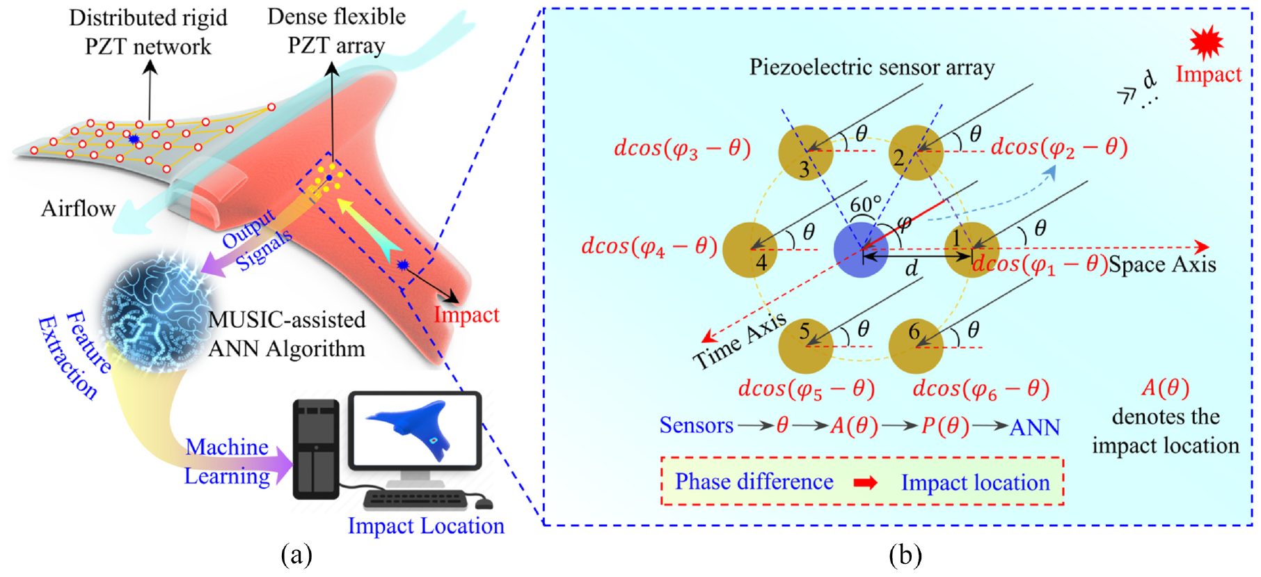
Architecture of the large-area structure health monitoring using the flexible piezoelectric sensor array. (a) Schematic illustration of the main architecture of the large-area SHM method via small-area flexible piezoelectric sensors and (b) the working mechanism of the large-area SHM method via monolithic small-area sensor array.
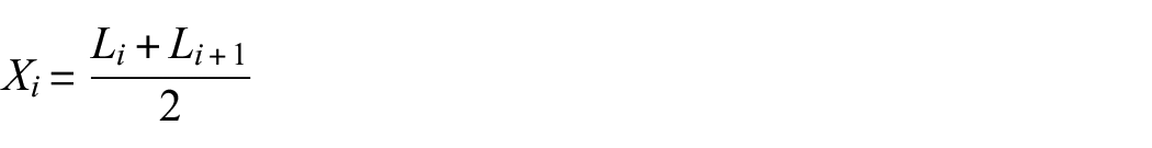
The working mechanism of the large-area SHM method via monolithic small-area sensor array is elaborated in Figure 1(b). When the impact is generated from a long distance, the difference of arriving time (the time when the impact wave reaches the sensors) between different units of the piezoelectric array is relatively small, but the difference on the spatial axis is quite obvious, that is, the spatial phase difference. The projection of the ith sensor on Time Axis can be expressed as
The working process of the proposed SHM method is illustrated in Figure 1(a). When the wing is impacted, the vibration caused by the impact is transmitted to the piezoelectric sensor array through the wing structure. Due to the piezoelectric effect, the impact signal is converted into 7-channel voltage signals (the sensor in the center as the reference signal and the six sensors around as the calculated part by the MUSIC algorithm) by the flexible PZT sensor array. In experiments, the applied impact and the voltage signals generated by the corresponding sensors are divided into two parts, namely, training data and real-time data. Voltage signals outputs of different impact regions are collected as data samples, and then transmitted to MUSIC algorithm for feature extraction. Finally, based on the feature differences between different impact positions, the ANN algorithm can complete the classification and recognition of the signals for impact location. Dissimilar to the previous SHM technology, in which the difference in the time sequence of impact signals arriving at the sensors is used as the major feature to distinguish regions, 41 the spatial phase difference is adopted as the main feature of impact location discrimination in this work. The MUSIC algorithm was especially introduced in this work to extract the feature differences of sensor output signals corresponding to different impact positions, as the training basis of the ANN algorithm. Hence, when a sudden impact occurs, the output signal of the piezoelectric sensor is input to the MUSIC-assisted ANN algorithm as real-time data, and the location of the impact can be estimated according to the training set, that is, the impact monitoring and positioning. The specific algorithm mechanism and implementation will be introduced in Principles of the MUSIC-assisted ANN algorithm in detail.
Fabrication process of the flexible piezoelectric sensors
The layered structure with specific materials and thickness of the designed flexible piezoelectric sensor array is shown in Figure 2(a). The sensors consist of four layers: polyimide (PI) substrate (30 μm), bottom Ti/Pt electrode (100 nm), PZT layer (600 nm), and top Ag nanowire (AgNW) ground electrode (100 nm). The size of the designed sensor array is 30 mm×36 mm with the thickness of about 30 μm, which makes it have good flexibility.
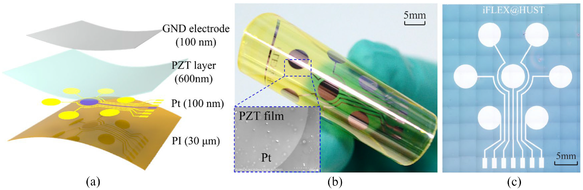
The designed structure and optical photo of the flexible piezoelectric sensor array. (a) The layered structure, materials and specific thickness of the flexible piezoelectric sensors, (b) photograph of the flexible piezoelectric sensors in bending status. The inserted SEM image shows a thin PZT film was covered upon the Pt electrode and (c) optical microphotograph of the flexible piezoelectric sensors.
It is well known that the PZT layer belongs to piezoelectric ceramic, which needs high temperature annealing up to 650°C to obtain good piezoelectric properties. Therefore, the fabrication of the flexible piezoelectric sensor cannot be carried out directly on the PI substrate, whose tolerable temperature is less than 250°C. Firstly, a PZT precursor film with 600 nm thickness was obtained by multiple spin-coating on a sapphire substrate (R plane) by the sol-gel method. After heating at 300°C for 20 min and rapid thermal annealing at 650°C for 10 min, high-performance ultrathin PZT piezoelectric ceramics were obtained. Then, the patterned bottom electrode (Ti/Pt) was prepared by photolithography (ABM/6/350/NUV/DCCD/M) and magnetron sputtering (TRP-450; SKY Technology Development Co., Ltd, CAS, Shenyang, China) successively, in which the Ti layer was used to increase the adhesion between Pt electrode and PZT layer. Afterwards, a layer of 30 μm PI was spin-coated on the sample as the flexible substrate. Finally, the interface between the sapphire and the PZT layer was irradiated by ultraviolet laser from the back of the sapphire (HUST LaserPeeler α). After laser ablation, the flexible piezoelectric sensor array was peeled off from the rigid sapphire substrate finally, where the process parameters of laser stripping PZT materials were illustrated in detail in our previous work. 42 In addition, the top common ground electrode of the sensors can be prepared by spraying silver nanowires or other conductive materials after the sensor is attached to the model, which will not be detailed here. It can be seen that the fabrication of the designed flexible piezoelectric sensor array designed only includes four steps, demonstrating its simple and cheap fabrication process.
Photograph of the flexible piezoelectric sensors in bending status (bending radius: ∼5 mm) is shown in Figure 2(b), where the flexibility is well demonstrated. The inserted Scanning Electron Microscope (SEM) image shows a thin PZT film was covered upon the Pt electrode. To be mentioned, the flexible sensors here do not contain the ground electrode, which can be made directly by spraying after the sensor has been attached to the structure. The Optical microphotograph of the flexible piezoelectric sensors is shown in Figure 2(c). Seven sensing units (diameter of 5 mm) with the common ground electrodes are designed as a ring array to form the sensing core of the SHM monitoring system.
Characterization and evaluation
The surface morphology and optical structure of the sensors were observed by scanning electron microscopy (SU3900; HITACHI, Tokyo, Japan) and ultra-depth three-dimensional microscope (DSX 510; OLYMPUS, Tokyo, Japan), respectively. As the bending radius changes, the variations in capacitance of the piezoelectric sensor was measured by a LCR meter (E4980A; KEYSIGHT, Penang, Malaysia). In the experiments, the multi-channel voltage signals of piezoelectric sensors were collected by the data acquisition equipment (PXIe-4302; National Instruments, Penang, Malaysia) and LabVIEW software, where the sampling frequency is 1 kHz. The impact load is applied by a small mallet and three impact hammers (BND-T020; BONAD Technology Co., Ltd, Shenzhen, China) of different energies (0.2, 0.35, and 0.5 J). The flexible sensors were adhered to the rigid structure (such as flat plate model and wing model) via epoxy resin glue (502, Kafuter), and stuck to the flexible model (such as PI strip) through aviation silicone rubber (K-704, Kafuter). All the adhesive processes were homogenized by the negative vacuum method. Conductive leads were welded and extracted from the pins of the flexible sensors via the conductive silver paint (CD-03, Conduction), which was cured at 120°C for 2 h or at 300 K for 24 h. The Computational Fluid Dynamics (CFD) analyses were conducted via COMSOL 5.4. The processing process of the MUSIC-assisted ANN algorithm is executed by MATLAB 2016.
Results and discussion
Properties of the flexible piezoelectric sensors for impact monitoring
The mechanical and electrical properties of the ultrathin flexible PZT sensor are characterized and compared with the popular commercial PZT sensor for the comprehensive evaluation of their performance. In order to simplify the experiment, a single flexible piezoelectric sensor unit with the same structure and thickness (30 μm) was prepared. The flexible sensor was mounted on a PI band (size: 20 mm × 200 mm, thickness: 100 μm), which could be bent into a cylindrical shape with different curvatures. Figure 3 shows the intrinsic capacitance variation of the flexible PZT sensor under different bending curvatures. It can be seen that as the curvatures become larger, the capacitance of the sensor gradually increases a bit but still less than 15%, which is consistent with the conclusion of previous reports. 43 A small increase in capacitance will influence the sensitivity of the piezoelectric sensors, but the functions of the sensors remain intact. In actual use, its curvature radius is a fixed value after the sensor is attached, so that the output performance of each sensor will not be affected by the curvature. Although the sensitivity of each sensor unit is different due to curvature or installation, the localization algorithm in this paper is immune to the output amplitudes in principle, so the influence of curvature on sensors will not change the results of the localization algorithm. The insets in Figure 3 show that the piezoelectric sensor without any buckling and wrinkling, maintains a good conformal adhesion to the PI band when the bending radius is 10 mm, and its output signal when the PI band is impacted. It demonstrates that the designed flexible PZT sensor still possesses excellent stability and performance on the curved surface. The materials of PI and aircraft wing are both non-stretchable, which exhibit similar conformal behavior. In addition, the curvature of the wing surface is less than 1 cm−1 in most parts. Therefore, the flexible PZT sensor can meet the mechanical conformation requirements of the curved wing surface.
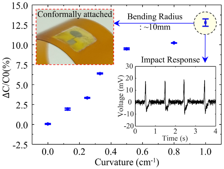
The intrinsic capacitance variation of the piezoelectric sensor under different bending curvatures. The insets show that the piezoelectric sensor maintains a good conformation attached to the PI band when the bending radius is 10 mm, and its output signal when the PI band is impacted. It demonstrates that the designed flexible PZT sensor still possesses excellent stability on the curved surface.
The influence of the designed flexible PZT sensor and the commercial rigid PZT sensor on the flow field of the wing surface was also investigated. The pressure distribution curves of the upper wing surface (NACA 0012, chord length 150 mm) with the two sensors and no sensors were calculated via CFD analysis, as shown in Figure 4. The inset shows the cloud images of pressure distribution on the wing surface with a flexible sensor (thickness: 50 μm) and a rigid PZT sensor (thickness: 500 μm) respectively. It was obvious that the rigid PZT sensor not only changed the pressure distribution at the mounting place, but also changed the pressure distribution over a large area of the other region of the wing surface, as indicated by the dotted ellipse in Figure 4. The interference of the rigid sensor to the flow field is much larger than that of the flexible sensor.
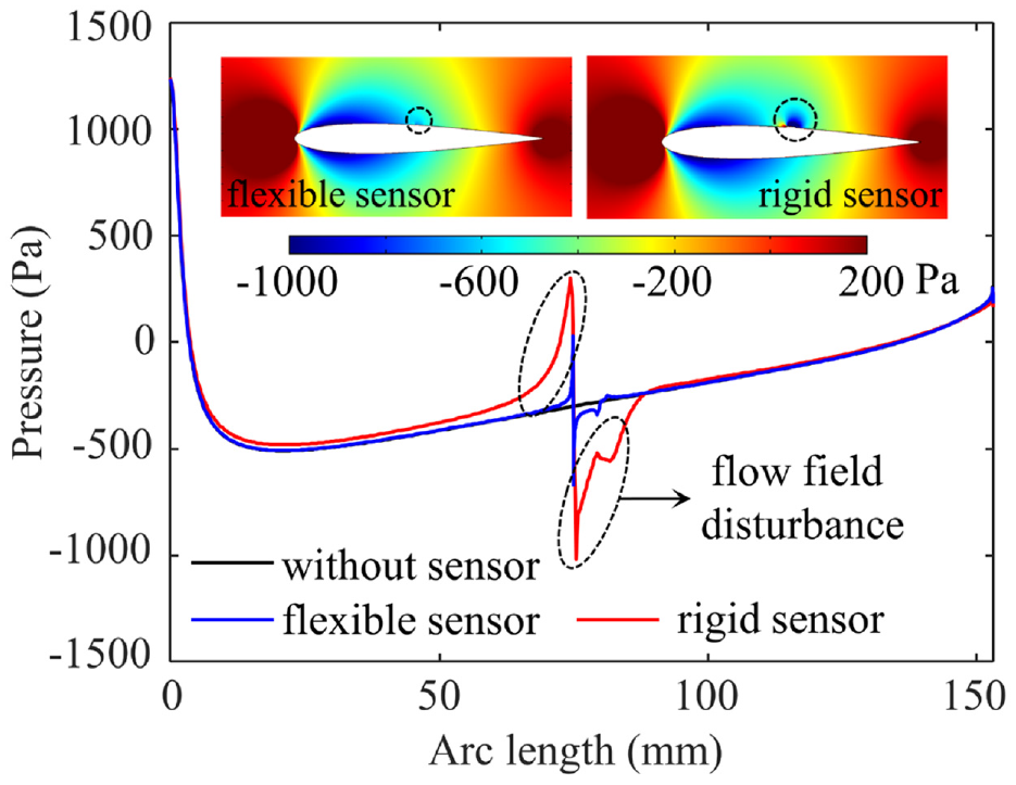
Comparison of the influence of flexible PZT sensors and commercial PZT sensors on the flow field of wing surface via CFD analysis. The inset shows the cloud images of pressure distribution on the wing surface when attached to the flexible sensor and the rigid PZT sensor respectively.
In order to verify the performance of the flexible PZT sensors in impact monitoring, the commercial rigid PZT sensor and the homemade flexible PZT sensor were attached to the adjacent position of the plate structure for contrastive analysis, as shown in the inset in Figure 5(a). Then an impact load was applied at a random position far from the two sensors. It can be approximated that the vibration wave caused by the impact was transmitted to the two sensors equally. The voltage signals of impact response collected from the rigid and flexible PZT sensors are shown in Figure 5(a) (red line: rigid PZT, blue line: flexible PZT). It can be seen that in terms of output amplitude, the peak voltage of the rigid PZT is around 20 times that of the flexible PZT, for the piezoelectric layer of the rigid PZT sensor is much thicker. The impact will cause the mechanical sound wave, which will form the voltage outputs via the PZT sensors when transmitted to the sensors. From the magnified view of the normalized waveform in Figure 5(a), the shape and envelope of the response output curves are relatively consistent with each other. They can clearly reflect the mechanical sound wave arriving at the sensor and the structural vibration caused by it, which are indicated by the dotted circle and square, respectively. On the other hand, the response time of the flexible PZT sensor is 14 ms as shown in Figure 5(a) which corresponds to the upper limit frequency of 71 Hz. The response time of the rigid PZT sensor is 8 ms and the upper limit frequency is 125 Hz in comparison.
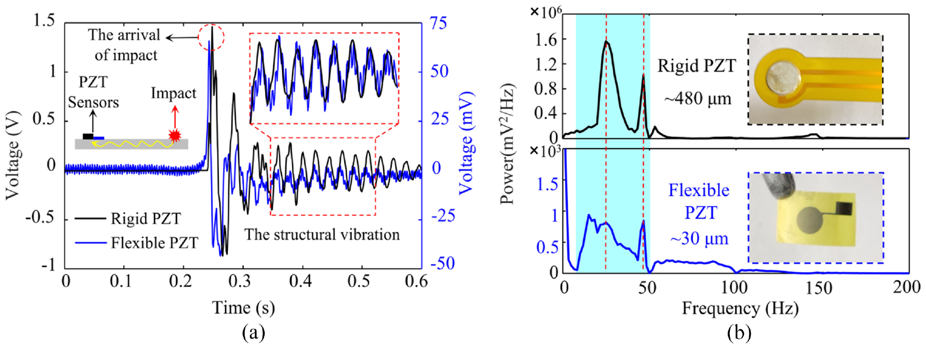
Electrical properties characterization and comparison of flexible PZT and rigid PZT sensors. (a) The voltage signals of impact response collected from the rigid PZT sensor and the flexible PZT sensor and (b) the spectrum analysis of the impact response curves of the rigid PZT sensor and flexible PZT sensor. The inset shows the photos of the rigid PZT and the flexible PZT sensor respectively.
Spectrum analysis was also conducted on the response curves of the two sensors, as shown in Figure 5(b), to compare the performance of the flexible and rigid sensors. Although the signal-to-noise ratio (SNR) of the flexible PZT sensor is inferior to that of the commercial rigid PZT sensor which causes that there is a DC component produced when passing through the filter, it does not affect the accuracy of the algorithm. The spectra of the two are basically consistent, therein, the main frequency component is basically matched. Thus, the electrical performance of fabricated flexible PZT sensor in impact monitoring is almost the same as that of the commercial sensor, although the SNR is slightly lower than the commercial sensor.
On the other hand, PZT piezoelectric ceramics were chosen instead of piezoelectric polymers such as PVDF because of considering the effect of temperature on sensors to finish the experiments in the Section Properties of the flexible piezoelectric sensors for impact monitoring. Generally, the temperature has a slight effect on the monitoring of impact energy, but has little effect on the accuracy of impact location which is determined by the phase difference of the sensor signals.
Moreover, the capability of the flexible PZT sensor array under different impact loads monitoring were also characterized. Meanwhile, the cooperative responses to the same impact signal were also verified for the seven sensors in the flexible PZT array. Figure 6(a) shows the voltage output signals of the flexible PZT sensor under the impacts of different energies (0.025, 0.2, 0.35, and 0.5 J respectively) via an impact hammer. As is well-known, when applying a force F to the surface of a piezoelectric sensor for
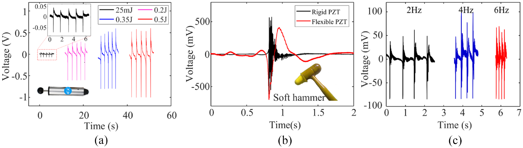
Characterizations of the flexible PZT sensors to impact load. (a) The voltage outputs of the flexible PZT sensor under the impact with different energy of 25 mJ, 0.2 J, 0.35 J, and 0.5 J respectively, (b) the voltage outputs of the rigid PZT sensor and the flexible PZT sensor under the impact of a soft hammer and (c) the voltage outputs of the flexible PZT sensor under the impact with different frequency of 2, 4, and 6 Hz respectively.
It is worth mentioning that the flexible PZT sensor can still detect the impact of very low energy (25 mJ) precisely, as shown in the inset of Figure 6(a). It not only demonstrates the extremely high sensitivity of the flexible PZT sensor, but also proves that the impact energy monitoring can be distinguished mainly by the output amplitude of the sensors, which is basically consistent with the previous related research work. 15
Additionally, it is found in the experiment that the fabricated flexible PZT sensor is obviously different from the commercial rigid PZT sensor in the response frequency band. A special silicone soft hammer was used to apply a soft impact as shown in the inset in Figure 6(b). The essential difference between soft impact and hard impact exists in the frequency band of mechanical waves excited in the structure disparate, where the frequency caused by soft impact is lower. Besides, a wider bandwidth in the low-frequency response is performed by the flexible PZT sensors. At this point, the voltage output comparison between the commercial rigid PZT sensor and the flexible PZT sensor is shown in Figure 6(b). It can be seen that the two sensors have an obvious response to the impact load, and the output voltage amplitudes are basically on the same level, which is completely different from the performance of the two under hard impact in Figure 5(a). In addition, due to the better low-frequency response performance, a higher signal-to-noise ratio than commercial PZT sensors is presented by the flexible PZT sensors. It can be easily concluded that the combination of flexible PZT sensors and rigid PZT sensors makes it possible to monitor impact hardness through the collaborative analyses of output amplitude and frequency. Figure 6(c) shows the output response of the flexible PZT sensor when impact loads of different frequencies (2, 4, 6 Hz) are applied periodically. It can be seen that the number of the impact can be well matched with the number of the peak of the output voltage over the same period of time, which means that the flexible PZT sensor can be directly used to monitor the impact frequency.
Generally speaking, the impact orientation can be distinguished according to the response difference of each sensor in the piezoelectric sensor array to the same impact load, such as amplitude and arrival time. Therefore, the coordinated response of the flexible PZT sensor array to the impact load was also characterized. The voltage response curve of the seven sensors is shown in Figure 7(a), where the inset showed the experiment setting: the fabricated flexible PZT sensor array was attached to an aluminum alloy plate and a mallet is used to apply an impact. It was indicated that all seven sensors can have an obvious response to the impact load. Figure 7(b) is an enlarged view of Figure 7(a), and the response time and peak response voltage statistics of each sensor are shown in Figure 7(c). It can be seen that the response time of each sensor to the same impact load is almost identical (10 ms), but the response amplitude is quite different due to the difference of curvature and mounting. That is, for distant impacts, there are no significant difference of arriving time between the impact occurring and the sensors responding, less than several milliseconds. The little difference is not sufficient for impact location in conventional time-difference-based SHM techniques. Otherwise, much more expensive data acquisition equipment with higher acquisition speed and sampling accuracy is essential. In addition, although the response amplitude of each sensor unit on the same impact is different, the trend of the signal characteristics and envelope is fairly consistent, which inspires us through space localization algorithm, to find the phase difference of each sensors, as the characteristic parameters for impact location. Impact location based on the spatial algorithm is not dependent on the output amplitude or the arriving time of each sensor. This method is more practical because of lower requirements for consistency in sensor fabrication and mounting. The specific principle and realization of impact location based on MUSIC-assisted ANN algorithm is illustrated in the next section in detail.
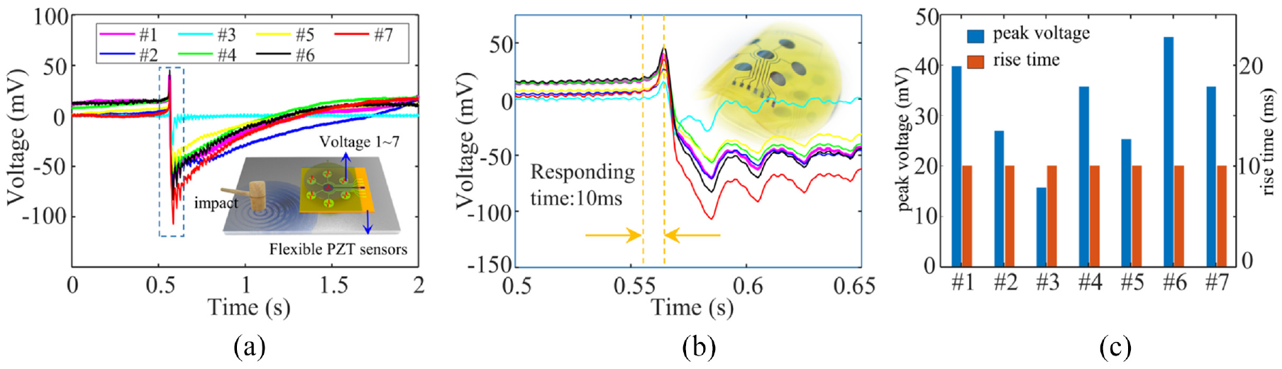
Characterizations of the flexible PZT array to impacts. (a) The simultaneous response curve of a flexible PZT sensor array under the same impact. Inset: Schematic diagram of impact experiment, where the fabricated flexible PZT sensor array is pasted to an aluminum alloy plate, and the mallet is used to apply an impact, (b) the partial enlargement of (a) and (c) the statistical response time and peak response voltage of each sensor.
Principles of the MUSIC-assisted ANN algorithm
The proposed large-area impact monitoring method based on monolithic flexible PZT sensors and Music-assisted ANN algorithm mainly focuses on the massive data processing of signals collected by PZT sensors and realizing impact localization through self-learning of ANN algorithm. However, there are two difficulties to be solved. Firstly, enough data samples (massive separate files of equal length) of the impact signal for each position is indispensable. Secondly, sufficient discrimination for features calculated by sensor signals at different positions is required. A large number of discrete data collections bring great complexity to the experiment and are not conducive to practical application. All the 100 groups of sample data of each location can be easily obtained in one experiment through continuous impact, but all the data are included in only one long file, which is not available for the ANN algorithm. It is necessary for the data segmentation algorithm to divide it into 100 independent data files of equal length, which greatly simplifies the difficulty of data collection. Secondly, if the ANN algorithm is trained only with the time-frequency features of the output signals of PZT sensors, the recognition rate will be quite low. Consequently, it is vital for us to introduce the MUSIC algorithm that can calculate spatial features, which improves the overall recognition rate of the algorithm abundantly. The data segmentation algorithm, MUSIC algorithm and MUSIC-assisted ANN algorithm will be elaborated successively.
Data segmentation
The self-learning MUSIC-assisted ANN algorithm is adopted to achieve large-area SHM. Massive impact data are required to train the ANN algorithm, but it is complicated to impact the structure intermittently. Hence, 100 times impacts are applied consecutively to obtain multiple samples in one test, where the time interval of each impact is kept at around 1 s to ensure the independence and integrity of each impact signal. The duration of each impact is less than 0.5 s from Figure 5(a). As to the signals in the continuous impact test, data segmentation based on minimum value search is given as:
where,
As shown in Figure 8(a), signals from different channels (background color: yellow) are segmented into multiple samples (background color: pink) via looking for the peaks of minimum value as the marking point of the data segmentation. Although samples in the same impact region are similar, distinctions among samples in different impact regions are indistinct. As a result, individual neural networks will lose the precision if samples were fed directly into networks, and the number of input nodes will be uncertain. The fusion of the MUSIC algorithm becomes irresistible to extract spatial features of sensor output signals and improve the accuracy of impact localization.
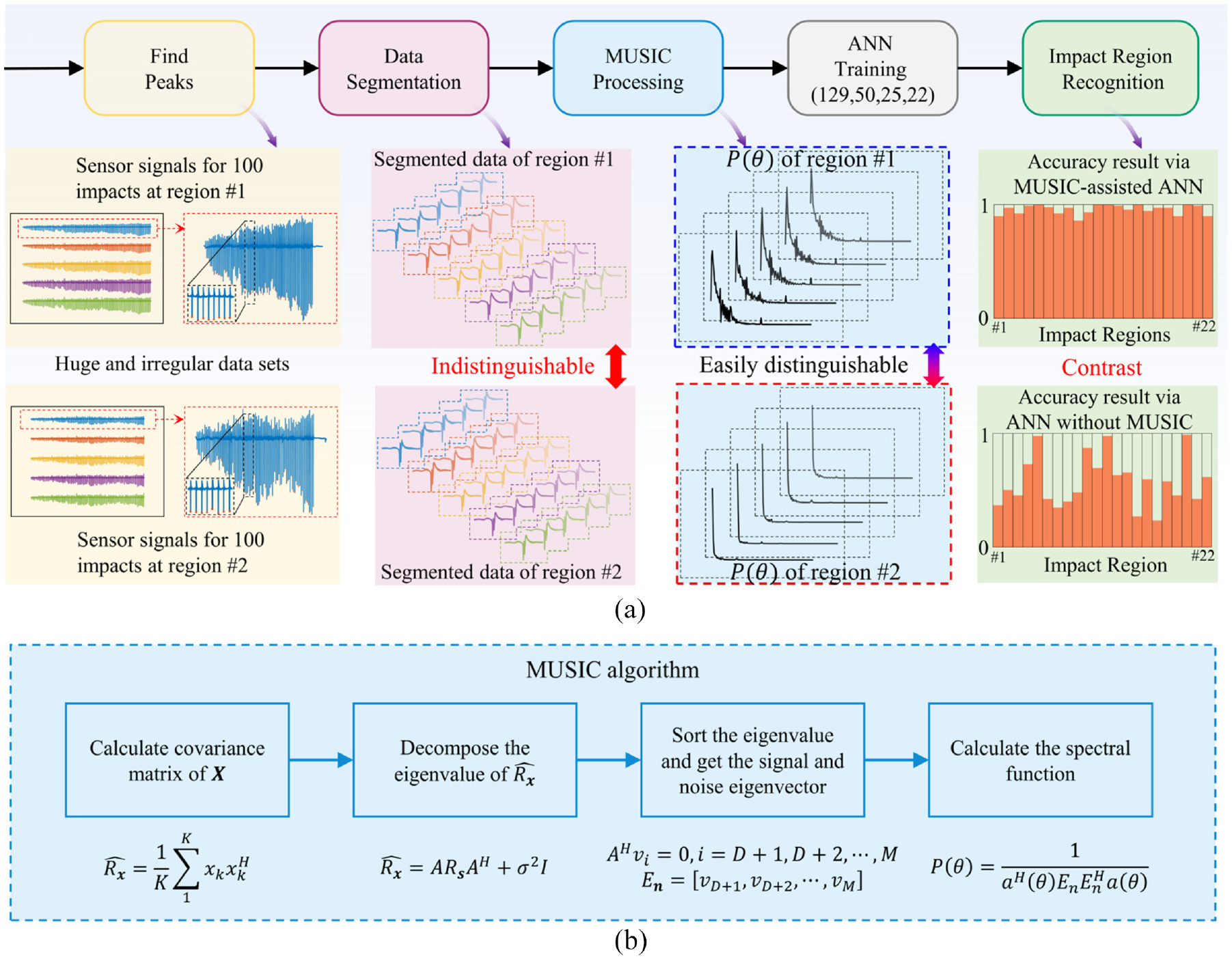
Working process and principles of the MUSIC-assisted ANN algorithm. (a) The working process of the MUSIC-assisted ANN algorithm and the main processing results of each step including the comparison of accuracy with or without MUSIC algorithm and (b) the specific implementing steps of MUSIC algorithm.
MUSIC algorithm
In order to improve the discrimination of output signals corresponding to different impact positions, MUSIC algorithm is used to calculate and extract spatial features from the signals and transmit them to ANN for training. Specifically, based on the subspace decomposition, it uses the orthogonality of the signal subspace and the noise subspace to calculate the spatial spectrum and then estimates directions of arrival (DOA) via spectrum searching.
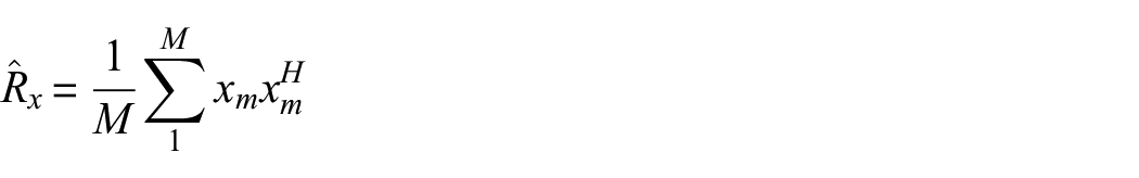
As shown in Figure 8(b), the MUSIC method is divided into four steps specifically. At first, the time domain matrix sensed by the array of flexible piezoelectric sensors is used to calculate the covariance matrix

where,
where, M is the total number of sensors and

where, A is the direction response vector, and
Based on the above, eigenvalue sort will distinguish signal subspace and noise subspace that are defined as:


where,
Finally, the spatial spectrum for the MUSIC algorithm is calculated to estimate DOA via spectrum search and is given as:
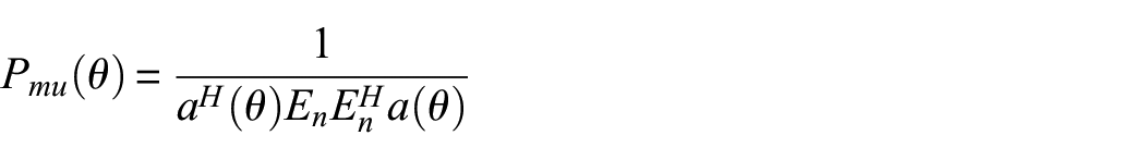
where,
MUSIC-assisted ANN algorithm
ANN connects neurons simulated by mathematical model into a network and is capable of self-learning and adaptive prediction. MUSIC-assisted ANN can accomplish impact region identification adaptively by utilizing self-learning. The adopted ANN normalizes the spatial spectrum of MUSIC, and fuses it into the input layer of the same length as itself. In the network, forward propagation consisting of an input layer, two hidden layers, and an output layer is applied at first to achieve initial identification. In the input layer, the output is not affected by an activation function, which is given as:

where,

where,

ReLU will improve the efficiency of gradient descent and backpropagation, for it avoids gradient explosion and gradient disappearance. At last, the output is passed to the output layer with the Softmax function to perform classifications. The Softmax function is given as:
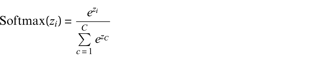
where,

where, O is the normalized output matrix and T is the target matrix that is encoded as the one-hot code.
The full process of forward propagation is illustrated above, and then the back propagation is applied. The basic idea of back propagation is to iterate all network parameters by calculating the partial derivative of L to the parameters. The method of iteration is gradient descent algorithm, and is given as:
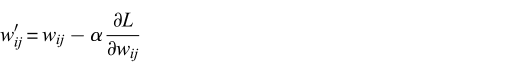
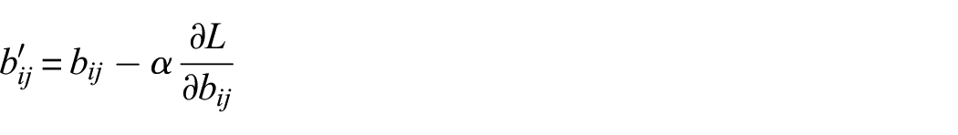
where,
Applications in impact localization of large-area structures
As shown in Figure 9(a), the fabricated flexible PZT sensor (size: 36 mm × 30 mm) was attached to a small zone in the middle of an aluminum alloy plate (size: 300 mm × 300 mm) to verify the proposed SHM technology, that is, the application of a small area sensor array in the impact monitoring and location for a large area. The four corners of the aluminum alloy plate to be tested are fixed to the table via the strong bond to facilitate the better transmission of vibration in the structure, where a mallet is used to apply the impact load. The whole model area to be tested was divided into 100 regions, and 22 representative regions numbered from R1 to R22 were selected for experimental verification of impact location, as shown in Figure 9(b). For all 22 positions tested, the positions in the same direction, such as R1, R2, were used to recognize impacts from different distances. The positions in the same distances, such as R3, R7, were used to recognize impacts from different directions.
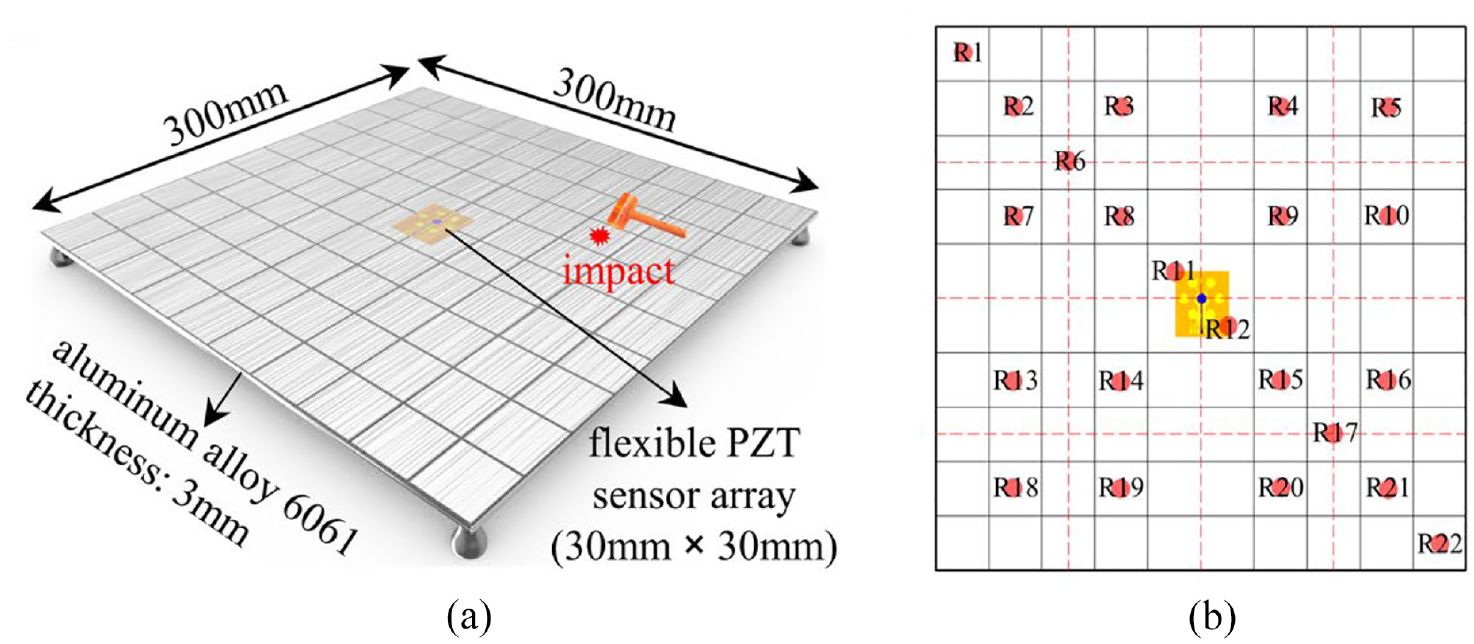
Applications in large-area structure health monitoring. (a) Impact location experiments setting on an aluminum alloy plate and (b) the division and numbering of impact regions on the plate ranging from R1 to R22.
According to the method shown in Figure 8, repeated impact loads of 100 times were applied to each of the 22 regions, and the output voltage signals of the flexible PZT sensor array were collected as the training set of the MUSIC-assisted ANN algorithm. In all the 22 positions, voltage output signals of six randomly selected positions (R1, R2, R3, R13, R19, and R22, respectively) are shown in Figure 10. It can be seen that there are only slight differences in voltage response signals between different impact regions.
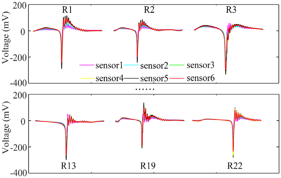
The voltage outputs of the flexible PZT sensors of different regions.
On the other hand, for the same impact region, the time-domain difference of the output voltage signals from different sensors units was also very small. It is not enough to be the features of the training set. Therefore, the voltage output signals corresponding to 22 different impact regions were converted into a spatial spectral waterfall diagram by MUSIC algorithm, as shown in Figure 11. It can be seen that the feature differences of spatial spectral curves at different impact regions were very obvious. Then, the spatial spectrum function of different impact regions served as the main features, which was then extracted and conducted via MUSIC–ANN algorithm, so as to obtain the accuracy of prediction of each impact region.
Spatial spectral feature of different regions calculated via the MUSIC algorithm.
The confusion matrix of the predicted accuracy is shown in Figure 12. The total predicted accuracy of the 22 impact regions to be measured was >92%, and the probability of misjudgment was extremely low (<8%). It was proved that the proposed impact monitoring technology for large-area structure by small-area flexible PZT sensors was feasible and reliable.
The confusion matrix of 22 impact regions on plate.
To visualize the prediction outputs, T-distributed Stochastic Neighbor Embedding (TSNE) was performed for 22 impact regions from ninety trials. Figure 13 shows the general classification of different impact regions visualized by TSNE. The result shows that the different impact regions were distinguished into different groups and the same impact region was clustered into a group by the MUSIC–ANN algorithm, which demonstrated excellent recognition capabilities of the algorithm.
TSNE for classification results from ninety trials of 22 impact regions. TSNE converts the 22-dimensional outputs into the 2-dimensional results to visualize the 22-dimensional data.
In addition, in terms of machine learning methods, the accuracy of the ANN algorithm and the K-Nearest Neighbors (KNN) algorithm were compared as well. The comparison of their prediction accuracy results for 22 impact locations is shown in Figure 14. It is obvious that the ANN algorithm is superior to the KNN algorithm. As a result, the ANN algorithm was chosen to combine with MUSIC algorithm to conduct impact monitoring and location.
The accuracy comparison between the ANN and KNN algorithm.
Finally, the applications of impact monitoring and localization on the real aircraft wing structure were also completed and verified, as shown in Figure 15(a). The airfoil was made of aluminum alloy 7075 in equal proportion according to the real aircraft wing, which possesses the characteristics of shifty surface curvature and variational section thickness. There are also some pressure holes and on the surface, joints, installation gaps, and other features of a real wing, which greatly limits the applications of traditional piezoelectric sensors on SHM technology. Thanks to the advantages of ultrathin thickness and good flexibility, the flexible PZT sensor proposed in this work can be directly attached to the curved surface of the wing, and hardly affect the flow field on the wing surface. And centralized, flexible PZT arrays, with fewer leads, are easier to be used for measurements on the wing. Similarly, the area to be measured of the wing was divided into 16 regions, numbered R1–R16, as shown in Figure 15(a). Likewise, 100 impact loads were applied on each of these 16 regions in turn for impact signals collecting. Next, the voltage signals were processed by the MUSIC algorithm to get the features, which were trained by the ANN algorithm afterwards. It is worth mentioning that the proposed impact monitoring technology didn’t rely on the data from all the sensors in the sensor array. The predicted accuracy with different number of sensors is shown in the inset in Figure 15(c). The recognition accuracy increased with the number of sensors, and the accuracy of five sensors and six sensors is both >90%. Therefore, if a few sensors failed due to fabrication or mounting, the remaining sensors can still complete the impact monitoring task, which greatly improves the robustness and reliability. Thereafter a random impact load was applied on the R6 region of the wing surface as indicated by the red marker in Figure 15(a). When the wing suffered a sudden impact, the flexible PZT sensor array outputs the voltage signal (as shown in Figure 15(b)), which was converted into a spatial spectrum function (as shown in Figure 15(c)) via MUSIC algorithm. By comparing the spatial spectrum function with the data of the training set, the predicted location of impact load could be obtained as shown in Figure 15(d) which was basically consistent with the actual impact position in Figure 15(a).
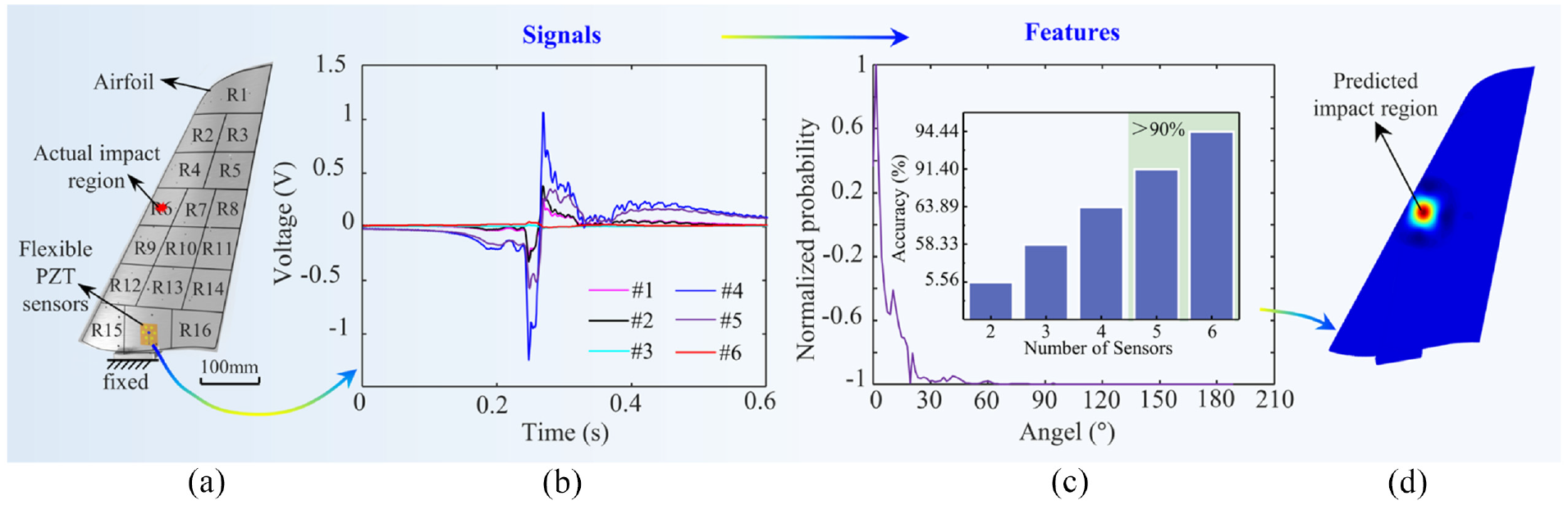
The impact monitoring and location applications on the aircraft wing. (a) Schematic diagram of flexible PZT sensor array mounted on the wing structure and the corresponding impact region division, (b) time-domain output signal of piezoelectric sensor when region R6 was impacted, (c) MUSIC processing results of output signal when region R6 was impacted, the inset shows the corresponding relationship between algorithm accuracy and number of sensors and (d) predicted location of impact occurrence region by MUSIC-assisted ANN algorithm.
Conclusion
In summary, an impact monitoring and localization method based on flexible monolithic PZT sensors and MUSIC-assisted ANN algorithm for large-area structures is proposed in this work. A flexible PZT array with the size of 36 mm × 30 mm, combined with the MUSIC-assisted ANN algorithm, was adopted to realize the impact monitoring and location in a region of more than 7500% of its area (area: 106,809 mm2), and the overall recognition accuracy was more than 90%. The results showed that the electrical performance of the flexible PZT sensor array is close to that of the rigid commercial PZT sensor network, but with much thinner thickness, smaller area, and fewer conductive leads. On the other hand, the MUSIC-assisted ANN algorithm shows high recognition accuracy and robustness. The introduction of the intelligent algorithm to monolithic flexible arrays greatly reduces the workload of theoretical analysis and data collection in traditional SHM technology, so as to endow this method better engineering practicability. Finally, it can not only be used for impact location, but also shows the potential of impact energy, impact frequency, and other structural and aerodynamic parameters, which shows a great application prospect in the integration monitoring of smart skin that combined SHM and aerodynamic measurements.
Footnotes
Acknowledgements
The authors thank the Flexible Electronics Manufacturing Laboratory in Comprehensive Experiment Center at Huazhong University of Science and Technology for support in advanced manufacturing equipment.
Author statement
The authors declare that the manuscript is an original contribution, and it is not being considered for publication elsewhere. All the authors have read and approved the manuscript. The corresponding author will handle all the communications hereafter.
Declaration of conflicting interests
The author(s) declared no potential conflicts of interest with respect to the research, authorship, and/or publication of this article.
Funding
The author(s) disclosed receipt of the following financial support for the research, authorship, and/or publication of this article: This work is supported by National Key R&D Program of China (2021YFB3200700), and the National Natural Science Foundation of China (51925503, 11932009).