Abstract
Epicyclic gearboxes are prevalent in a variety of important engineering systems such as automotive, aerospace, wind turbines, civil equipment and industrial robots owing to the merits of compact structure and high power density. To ensure the productivities of such important systems, condition monitoring techniques are being actively studied to resolve the challenge of varying transmission paths and multiple modulations in vibration signals acquired from ring gear housing. This paper proposes a new Modulation Signal Bispectrum (MSB) Enhanced Squared Envelope method to analyse the vibration signals acquired by a special On-Rotor Sensing (ORS) transducer that is mounted on the shaft of an epicyclic gearbox. A vibration signal model of ORS measurements from epicyclic gearboxes is presented to show the multiple modulation influences. Moreover, inevitable noise influences are also investigated on the conventional squared envelope and the state-of-the-art spectral correlation analysis. On this base, MSB is introduced to suppress these influences for accurately extracting equally spaced harmonics in the squared envelope and is then integrated to isolate fault signatures, allowing effective fault detection and diagnosis of epicyclic gearboxes, which lead to novel contributions of an MSB Enhanced Squared Envelope (MSB-ESE) approach. An experimental study of compound epicyclic gear faults was conducted to demonstrate the superior performance of MSB-ESE along with the special ORS technique in detecting and diagnosing the compound faults on sun and planet gears.
Introduction
Epicyclic gearboxes are widely used in critical machines like wind turbines and aircrafts owing to the unique merits of large transmission ratios and strong torque bearing capacity. Epicyclical gearboxes are usually working at rough conditions and the elements including gears and bearings are vulnerable to various faults, for instance, pitting and fatigue cracks. Fault detection and diagnosis of epicyclical gearboxes at early stages are substantially desired to increase machine reliability and prevent machine failures.
Fault detection and diagnosis of epicyclic gearboxes have attracted substantial attention. 1 Compared with the fixed-axis gearboxes, it is more problematic to detect and diagnose the incipient faults in epicyclic gearboxes because the varying rotating centres of planet gears include the diverging transmission path of the gear sets. Vibration-based monitoring techniques have been advanced significantly in the last two decades. Large quantities of research were carried out based on the vibration signals obtained from the gearbox housing. Inalpolat and Kahraman 2 explained the modulation mechanisms of the sidebands in vibration signals from an epicyclic gearbox. They explained the amplitude modulation due to the carrier rotation in the health condition; however, the change when gear faults occur induced additional frequency modulation is not included in the models. With the following investigation, Inalpolat and Kahraman 3 developed a nonlinear time-varying dynamic model to explain the sidebands due to amplitude and phase modulation in vibration signals due to manufacturing errors.
Feng and Zuo 4 proposed the on-housing vibration signal models of the common epicyclic gearbox faults. The signal model considers the local amplitude modulation (AM) and phase modulation (PM) effects and the signal propagating paths when gear fault occurs. These studies explained the vibration signals obtained from the stationary part, typically the housing or ring gear. Given that On-Rotor Sensing is a novel measurement method, modulation phenomena in vibration signals captured from the rotating parts are not well characterised in literature, which will be analytically explained in this paper.
Large quantities of advanced signal processing methods are proposed to monitor the health conditions of epicyclic gearboxes through vibration signals obtained from gearbox housing. Blunt and Keller 5 introduced two novel methods of synchronous average analysis of the vibration signals for diagnosing the fatigue crack in the carrier of an epicyclic transmission system. The vibration signals of faulty epicyclic gearboxes are rich in discrete components due to both amplitude modulation (AM) and phase modulation (PM) induced by gear defects and the additional amplitude modulation from the periodic varying transmission paths. Feng et al. 6 used an ensemble empirical mode decomposition (EEMD) method to decompose vibration signals into multiple monocomponent signals for accurate amplitude and frequency demodulation analysis. The developed approach is verified by the simulation and the experimental studies of a wind turbine epicyclic gearbox. With further studies, Feng et al. 7 developed a joint amplitude and frequency demodulation method based on local mean decomposition (LMD) to extract the characteristic fault frequencies of epicyclic gears. Wang et al. 8 developed a meshing resonance-based filtering algorithm to detect the ring gear faults. This method can highlight the fault information without using a baseline signal while neglecting other undesired responses. Nonstationary working conditions are a typical case in epicyclic gearboxes and many emerging methods are developed to characterise the nonstationary vibration signals. Vibration responses from epicyclic gearboxes under nonstationary working conditions are time-varying in nature and the varying multi-components and strong background noise are the critical challenges for fault detection and diagnosis. Feng et al. 9 proposed iterative generalised demodulation without the need for tacho signals for monitoring epicyclic gearboxes under nonstationary conditions. Compared with the order tracking methods, the generalised demodulation based approaches can avoid the interpolation errors in the step of angular resampling. Sawalhi, Randall and Forrester 10 proposed a tacholess order tracking method to separate the gear and bearing fault signals for diagnosing epicyclic gearboxes in wind turbines. Hou et al. 11 improved the generalised demodulation using dual path optimisation ridge estimation, leading to a tacholess order tracking approach in fault detection of wind turbine epicyclic gearboxes.
Despite the advanced demodulation and decomposition methods, envelope analysis is still popular in fault diagnosis of epicyclic gearboxes. Due to time-varying transmission paths, the time-synchronous averaging (TSA) method is not sufficiently capable to improve the signal-noise ratio (SNR) of vibrations. Guo et al. 12 proposed an envelope signal based TSA method to maximise fault signature strength. Wang, Shao and Cao 13 pointed that the envelope analysis cannot effectively distinguish the fault signatures from the unrelated modulation components. To improve the diagnostic performance of envelope analysis, a genetic algorithm based sub-band selection method was developed to determine the optimal demodulation frequency band for sun gear crack diagnosis. Mauricio and co-authors 14 implemented the cyclostationary analysis to diagnose the bearing faults in an epicyclic gearbox from a wind turbine. The enhanced envelope spectrum is a promising approach for monitoring wind turbines. Dziedziech et al. 15 developed Instantaneous Circular Path Cycle Map (ICPCM)–based envelope analysis and time-synchronous averaging analysis for epicyclic gearbox fault detection. The ICPCM method consumes substantial computing resources. Although envelope analysis is a relatively effective way to detect and diagnose epicyclic gearbox faults, random noise is an unavoidable challenge when applying it for fault detection and diagnosis. Envelope analysis is the mainstream technology in processing the vibration signals of rotating machines. However, envelope analysis has shortages of noise inclusions 16 and complex spectrum profiles which make it difficult to separate fault components and achieve an accurate diagnosis, especially for the data with low SNR due to incipient defects in planet, long vibration transmission paths, and variable operating conditions. The vibration signal from an epicyclic gear system in a commercial helicopter was investigated via envelope analysis by Elasha1 et al. 17 and Zhou et al. 18 . A comprehensive literature review was given by Lei 19 from the perspectives of modelling and analysing. The difficulties of fault detection and diagnosis desire more advanced sensing and processing methods. Fan and Li 20 installed a commercial accelerometer on the planet carrier using a slip ring to detect and diagnose planet bearing faults. The novel implementation can avoid the complex transmission path, but this method needs a significant modification on epicyclic gearboxes. Then, cepstrum whitening, minimum entropy deconvolution (MED), spectral kurtosis (SK), and envelope analysis are used to develop a logic detection and diagnosis routine.
In this paper, aiming to minimise the effect of varying transmission paths, On-Rotor Sensing (ORS) is employed to capture rotor vibrations. The modulation mechanism in ORS vibrations is analytically characterised to show the differences with conventional on-housing vibrations. The noise influence in envelope analysis is given in this paper. The noise and rich components in the squared envelope prevent effective fault diagnosis of epicyclic gearboxes. To further enhance equally spaced modulation harmonics in the squared envelope, Modulation Signal Bispectrum is employed to extract the equally spaced harmonics for effective fault diagnosis of compound faults of epicyclic gearboxes in the experimental study. The theoretical background including characteristic frequencies of epicyclic gearboxes, noise envelope properties and MSB method, is described in the Theoretical Background section. The experimental studies of data sensing and signal processing are given in the Gear Fault Diagnostics in an Epicyclic Gearbox section. Finally, the conclusions are drawn in the Final section.
Theoretical background
Epicyclic gearbox vibration characteristics with faults
A typical epicyclic gear set has a ring gear, several planet gears and a sun gear. If the ring gear is standstill, the planet gears rotate around the unfixed centres and mesh with the ring gear and sun gear simultaneously. The planet gears not only rotate around the moving centres but also revolve around the sun gear. The meshing stiffness varies significantly along with the number of meshing teeth during the gear train rotation and consequently, gear meshing vibrations are rich in periodic components. Several planet gears are meshing simultaneously with the sun gear and the ring gear, and a large number of similarly periodic components could exist in the vibration of epicyclic gearboxes. These same periodic vibrations with different meshing phases are coupled with each other. 5 In addition, the vibration responses are transmitted to on-housing accelerometers through multiple and time-varying transmission paths. These complex transmission paths attenuate the desired fault information, 19 and additionally, large quantities of background noise are added into the vibration signals, which is the most challenging problem in the fault diagnosis of epicyclic gearboxes.
Fault characteristic frequencies of epicyclic gearboxes
To introduce the characteristic frequencies of the epicyclic gearbox, the corresponding nomenclature is defined here. In this paper, ZR, ZP and ZS are the tooth number of the ring gear, planet gear and sun gear.
K denotes the number of planet gears. f rc , f rp and f rs are the rotating frequency of the carrier, the planet gear and the sun gear, respectively.
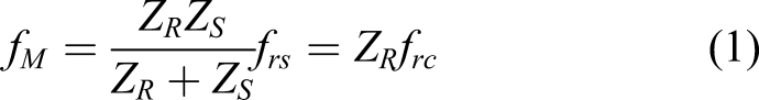
The meshing between the planet gear, the sun gear and the ring gear determines that the passing tooth number in rotation is the same, and thereafter, the meshing frequency of the planet gear and the ring gear is the same as that of the sun gear and the planet gear. f
M
is the meshing frequency of the epicyclic gearbox. The rotation frequency of the shaft connected with the sun gear is known as f
rs
, and the meshing frequency can be calculated as
A localised tooth defect on the gears results in periodic impulses, which are modulated by the meshing frequencies and natural frequencies of the gearbox. If the localised fault occurs on the sun gear, the vibration responses become pronounced when the fault meshes with a planet gear and then go back to a normal condition when the fault runs out the meshing area. With the rotating of the sun gear, the fault meets K planet gears consecutively. Assume that the impacts between the fault on the sun gear and the planet gears are identical. The characteristic fault frequency of the sun gear is
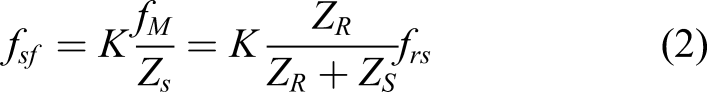
The identical impacts induced by faults are a hypothesis, and due to the manufacture and installation errors, the localised defect induced impacts are varying especially under nonstationary working conditions. Therefore, the non-integer
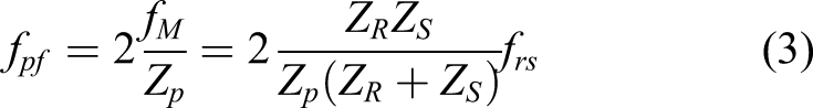
Similarly, when the planet gear has a localised defect, the collisions induced by the defect would happen twice with the sun gear and the ring gear in one revolution. Hence, the characteristic fault frequency of the planet gear is expressed as
Vibration signal model of faulty gear meshing
The faults on planet and sun gears result in an AM/PM effect to the gear meshing vibration.
4
The main difference is that two faults generate different characteristic frequencies. If the transmission path is not inclusive, the modulation signals of gear meshing can be simulated as an AM/PM signal. The meshing frequency of gear pairs is the carrier and the fault characteristic frequency is the modulating signal. Therefore, the modulation signal of the vibration can be expressed as
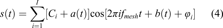
with
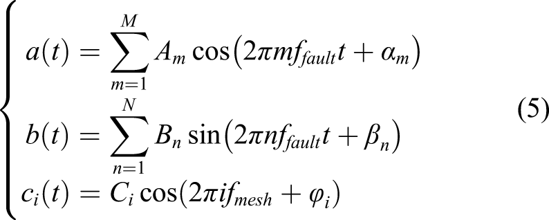
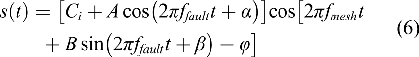
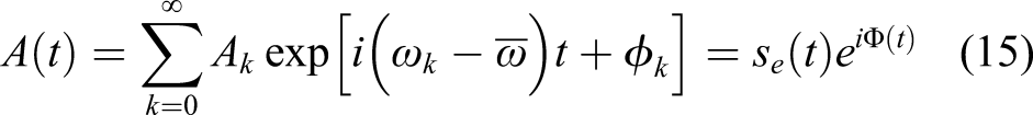
The model can be expanded using the Jacobi–Anger expansion, which can be expressed as
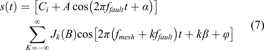
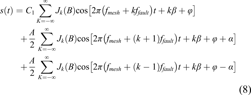
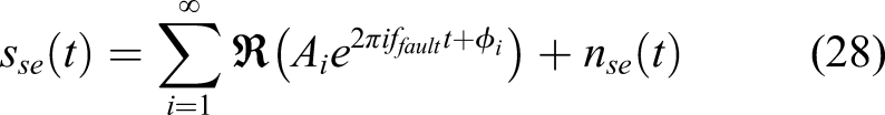
It can be seen from equation (8) that the vibration signal from a faulty gear pair has numerous sidebands around the meshing frequency
Figure 1 shows a schematic diagram of the ORS sensor installed on an epicyclic gear set. The ORS accelerometer is directly attached to the carrier rotor and rotates with the carrier simultaneously. ORS sensor on an epicyclic gear set.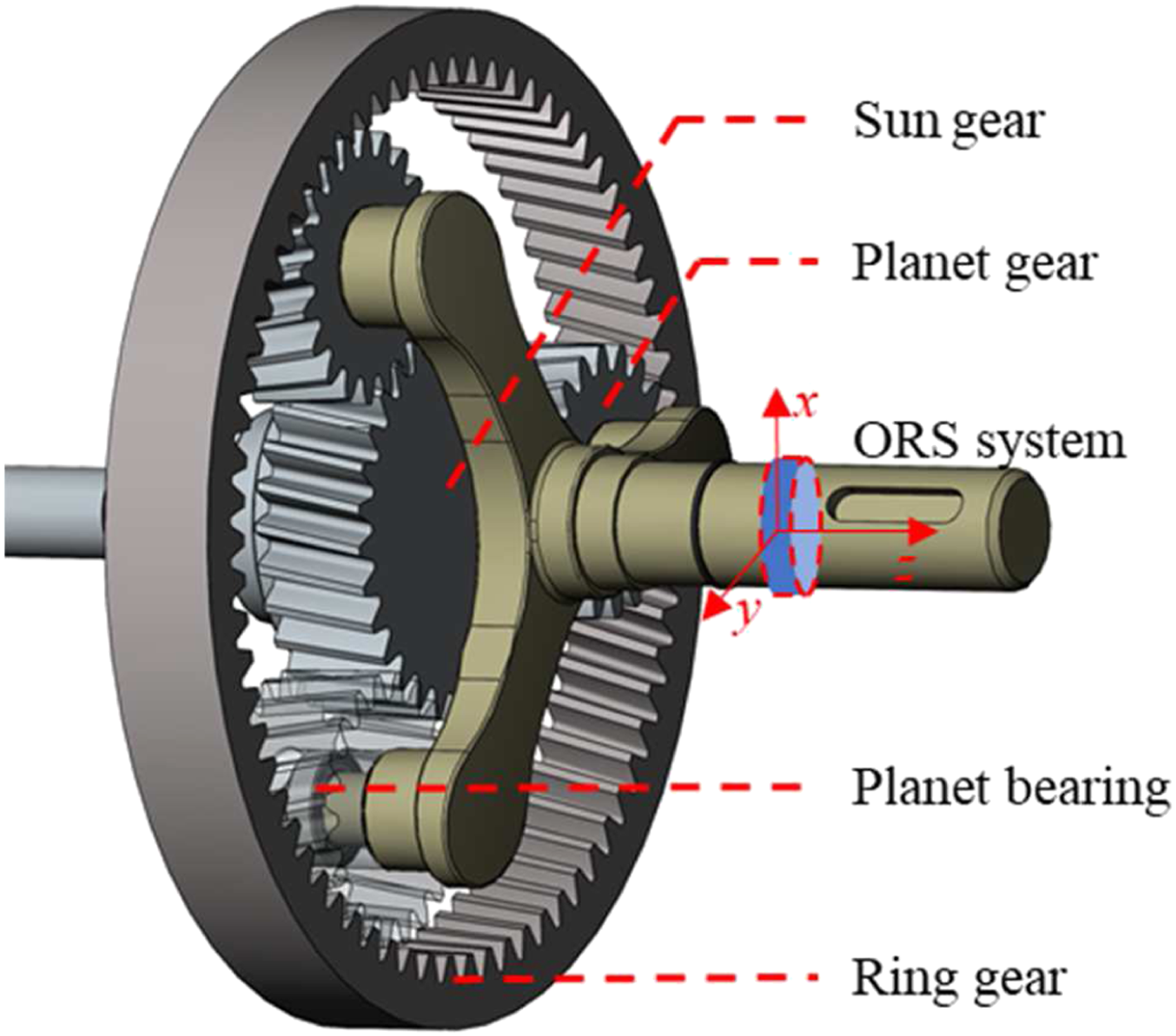
Imaging that the gears and bearings are isotropic, the planet gear fault induced AM/PM vibration signals can be directly captured by the tri-axis ORS accelerometer. The localised fault on the planet gear has a fixed angle with the three axes of the ORS accelerometer when meshing with the sun gear or ring gear. Owing to the fixed transmission path, no additional modulation is involved and consequently, the planet gear fault induced AM/PM vibration of ORS measurements can be expressed by equation (6), which then can be expanded into a sum of multiple components by equation (8).
To be different, the relative speed between the sun gear and planet gear inevitably results in additional modulation. The relative movement results in a varying angle between the impacts and the sensor axis. The projection of the vibration onto the sensor axis introduces the additional modulation effect, which can be modelled using a Hanning window.2,3 The ORS vibration of the sun gear fault can be expressed by
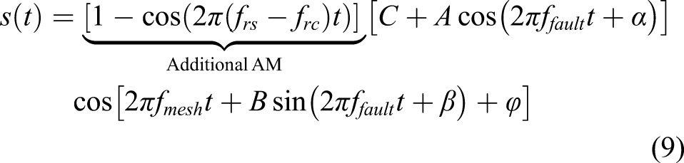
For the sun gear fault, the characteristic sun fault frequency is
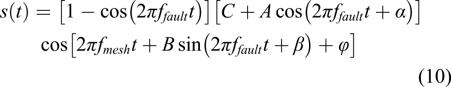
It can be seen that the additional modulation is also related to the characteristic fault frequency of the sun gear. The additional modulation can be avoided if installing another ORS sensor on the shaft connected to the sun gear. To make the condition monitoring cost-effective, only one ORS sensor is installed on the carrier shaft. The modulation signal of ORS measurements for the sun gear fault case can be expanded into a sum of multiple components, which is expressed as follows
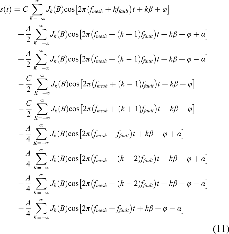
It can be observed from both faulty cases of planet and sun gears by equations (8) and (11) that the ORS measurements from malfunction epicyclic gearboxes are rich in multiple components around the meshing frequencies. These equations are an ideal condition for perfect epicyclic gearboxes under stable working conditions. However, the manufacture and installation errors, as well as transiently unstable working conditions, lead to random phase variation and additional discrete components, making the fault detection and diagnosis more challenging and in addition, strong background noise increases the difficulty further. To restrain the random phase variation, the squared envelope analysis is used to characterise second order cyclostationary ORS vibrations.
Noise and multiple components in envelope analysis
Squared envelope
The envelope of a random signal was defined by Rice in reference 22, which is described as follows. Assume that the signal is
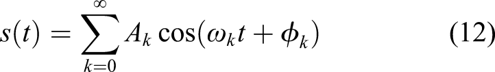
in which
Here,
The envelope of the signal can be obtained easily based on the Hilbert transform, which alters the phase of every component by

in which H( ) denotes the Hilbert transform of the time domain signal. Both the real and imaginary parts yield to a normal distribution if the signal
Envelope analysis is prevalent in fault detection and diagnosis of rolling element bearings and it has been demonstrated that envelope analysis is powerful to characterise cyclostationary signals. The effectiveness of the envelope analysis is owing to that the envelope detects the energy oscillation of the signals. The envelope yields spurious high-order harmonics in the spectrum due to the inevitable aliasing problem, whilst the squared envelope can prevent producing sharp to avoid the possible aliasing.
23
The squared envelope has more merits because it has a strong connection with another effective approach, spectral correlation, for analysing the cyclostationary signals.
23
The relationship between squared envelope and spectral correlation is described in the following contents. The spectral correlation is defined as
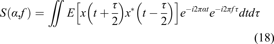
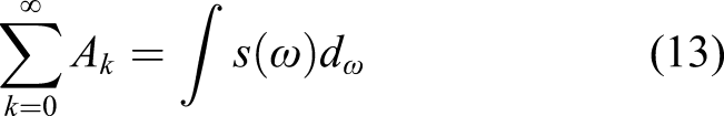
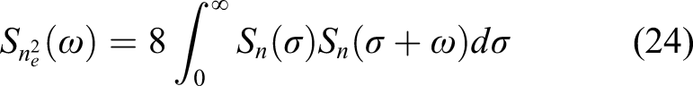
The spectral correlation results have the cyclic frequency and normal frequency axis and the integral of the spectral correlation along the normal frequency axis leads to a discrete spectrum of the cyclic frequency axis,
24
yielding
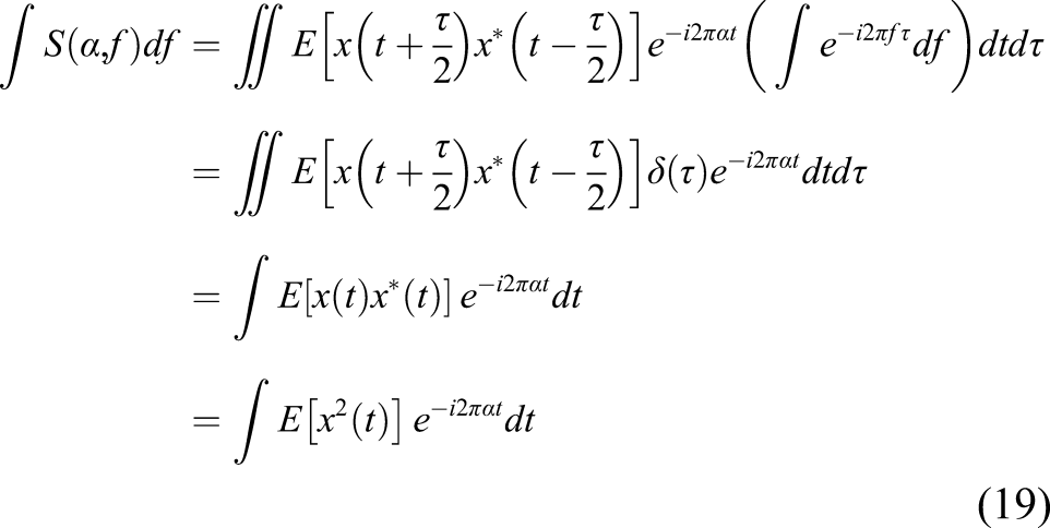
The integral of the spectral correlation over normal frequency is equivalent to the spectrum of the squared signal. However, the squared operation of real signals inevitably brings additional components due to the aliasing effects.
23
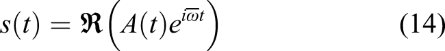
In contrast, the squared operation can be achieved by the analytic signal multiplying with its complex conjugate, which is also called squared envelope. The squared envelope can be expressed as

The squared envelope does not involve the additional components but the desired diagnostic information only. Therefore, the squared envelope often serves as an effective method to characterise the cyclostationary signals. However, vibration signals acquired from a running machine is always subjected to random noise interference. The calculation of squared envelope by such methods inevitably includes noise influences, resulting in inaccurate demodulation results.
Noise in envelope analysis
The linear property of the Hilbert transform allows a linear representation of the analytic signal. Assume that the original n
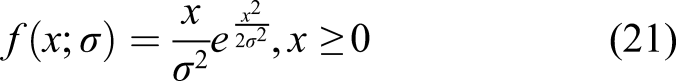
The example of the noise signal and its envelope is shown in Figure 2(a) and the probability density functions (PDFs) of the noise signal and the envelope signal are depicted in Figure 2(b). The noise is the noise itself obeys the normal distribution and the envelope obeys the Rayleigh distribution. PDFs of the random noise and its envelope.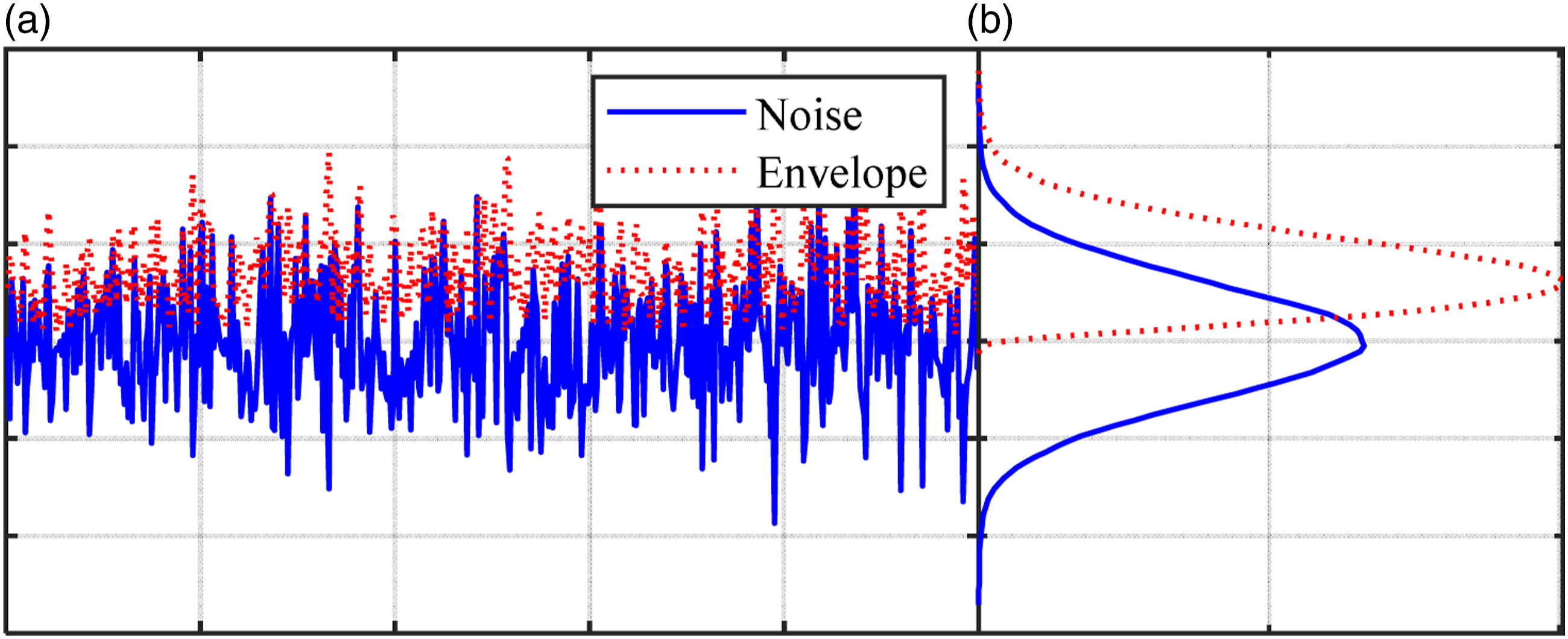
The statistical characteristics25,26 of the squared envelope


E( ) and D( ) denote the mean value and the variance;
Moreover, the envelope n
e
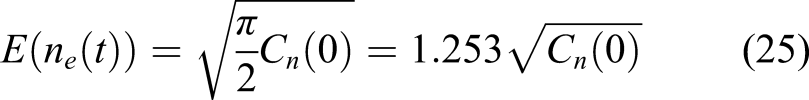

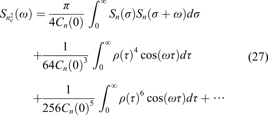
It can be seen that the noise still presents in the envelope signal but the normal distribution change to the Rayleigh distribution. The noise deteriorates the desired fault signatures, and therefore, noise reduction is required to extract accurate fault features.
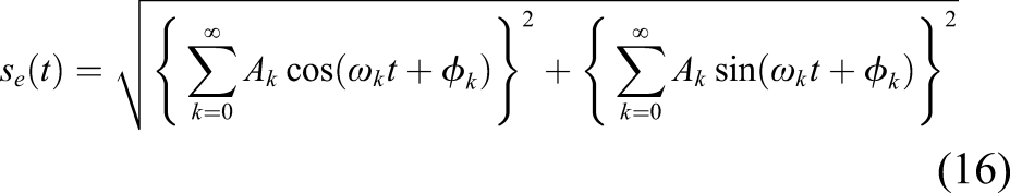
Multiple harmonics in the envelope
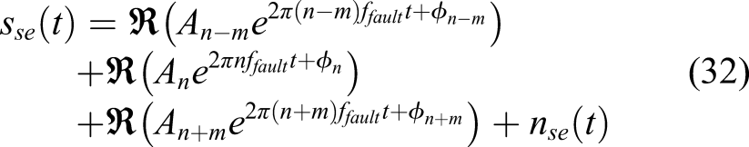
It can be seen from equations (8) and (11) that there are numerous sidebands around meshing frequency in gear vibrations. The squared envelope can obtain the envelope signal that contains plentiful harmonics of the fault frequency. However, the demodulation process inevitably involves other components that are not related to the gear faults. The epicyclic gear faults can induce numerous harmonics in the squared envelope signal which can be expressed as


with
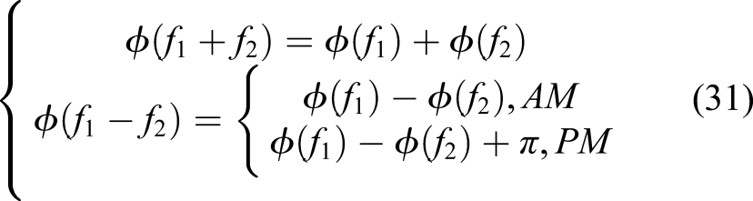
The phase of
The phase of
Gear fault diagnostics in an epicyclic gearbox
ORS measurements from an epicyclic gearbox test rig
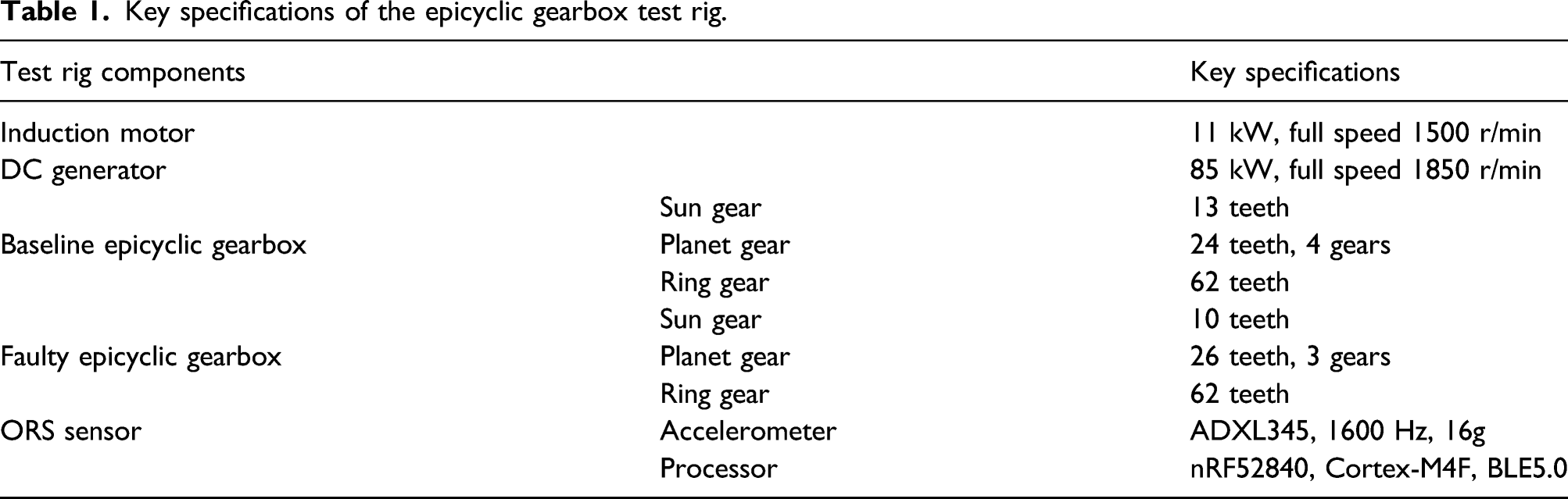
The experimental studies were conducted to demonstrate the effectiveness of the MSB Enhanced Squared Envelope approach. The schematic diagram and photograph of the epicyclic gearbox test rig are shown in Figure 3. Two back-to-back 10 kW epicyclic gearboxes are connected by the flexible couplings as the speed reducer and increaser, respectively in the transmission line. The power source of the test rig comes from an induction motor and is consumed by the DC generator. Schematic diagram and photograph of the epicyclic gearbox test rig.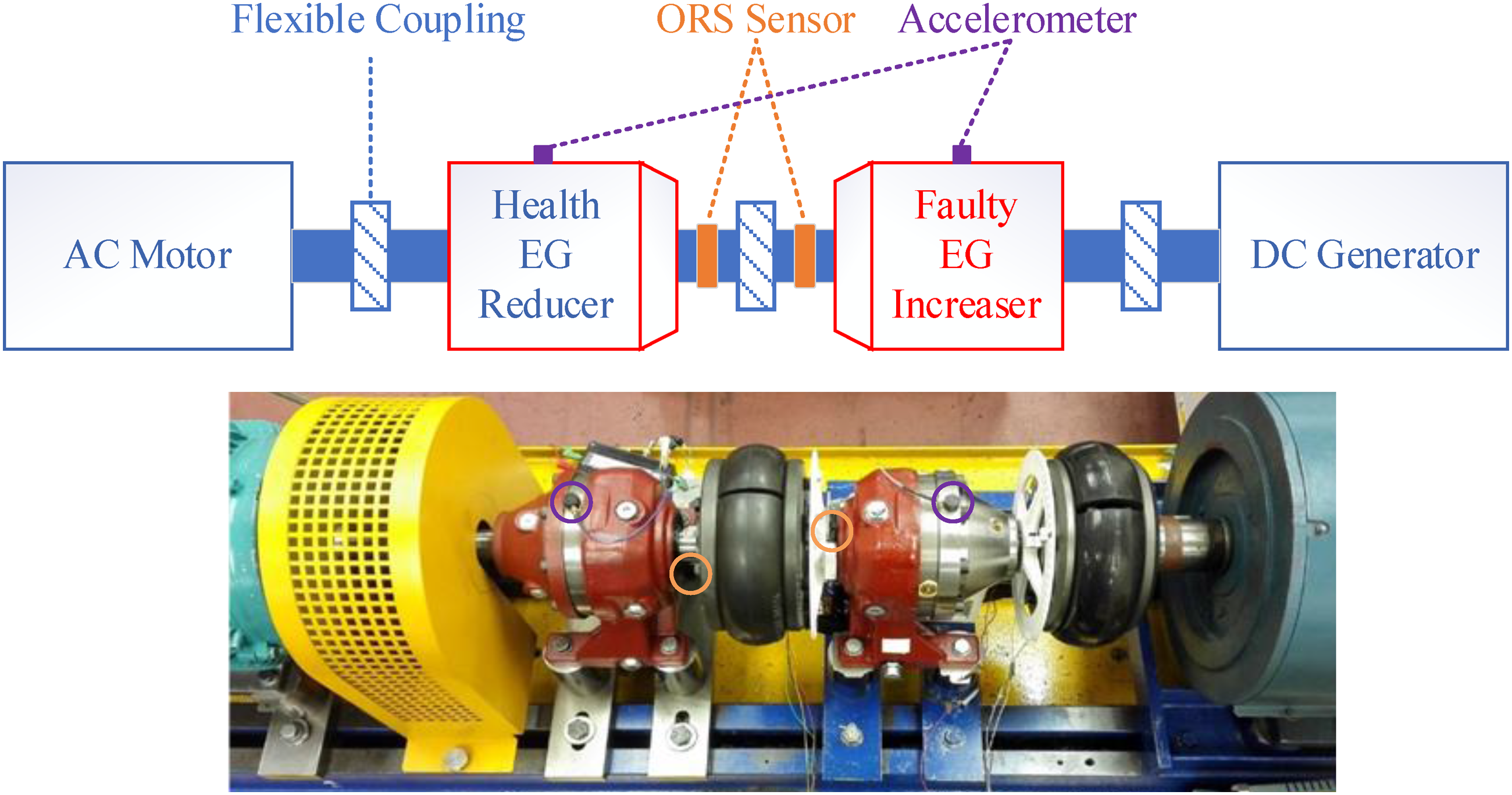
Key specifications of the epicyclic gearbox test rig.
One of the epicyclic gearboxes is healthy and it is considered as the baseline in the experimental studies and the other one has compound defects on the sun gear and planet gear, respectively. The photographs of the gear faults are shown in Figure 4. Figure 4(a) shows that the fault on the sun gear is simulated by removing around 60% of the gear tooth face along the width and Figure 4(b) depicts the planet gear defect is seeded by milling about 60% of the tooth face. Photographs of gear faults (a) sun gear fault (b) planet gear fault.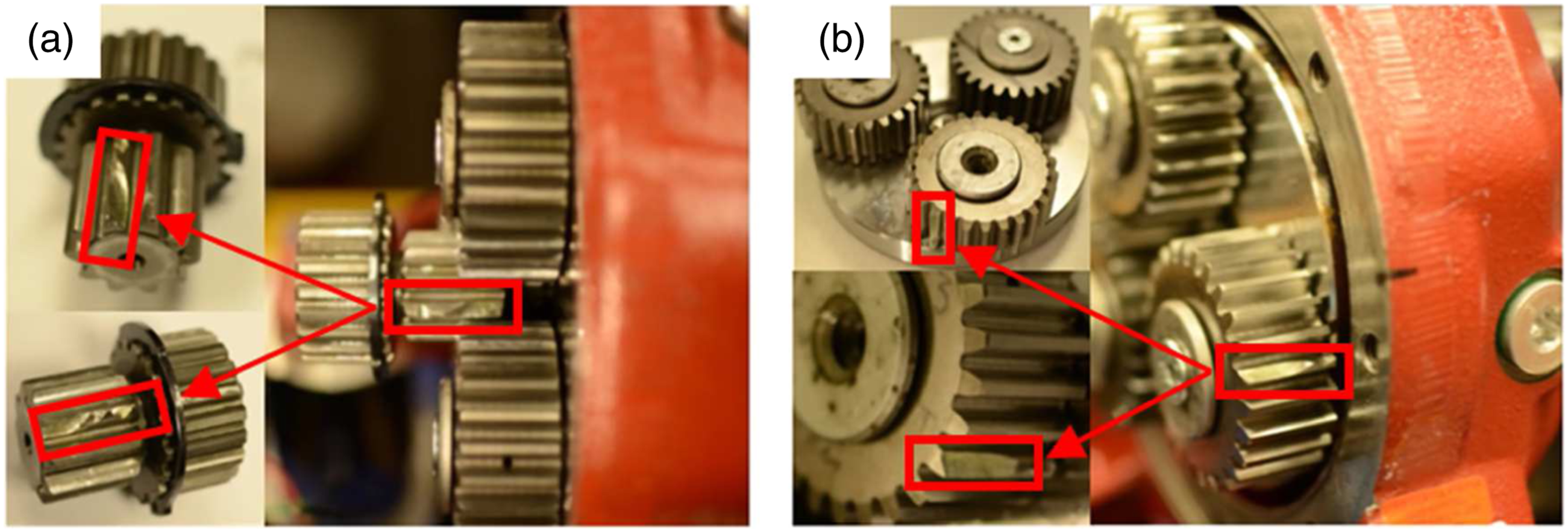
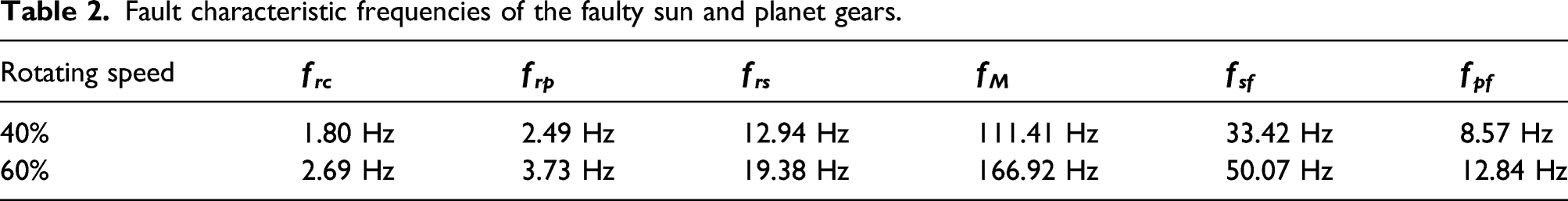
Fault characteristic frequencies of the faulty sun and planet gears.
Conventional squared envelope analysis
As introduced in the description of the experiments, ORS signals represent the vibration of the rotors. The MEMS accelerometers are collecting the absolute accelerations and consequently, the main component of the ORS vibrations is the alternation of gravity along with the rotation of the shaft. The results of envelope and MSB-ESE used the ORS vibrations at speed 60% and load 90% as an example to explain. The MSB-ESE results at other working conditions are provided in the Appendix 1. Figures 5(a) and (c) display the temporal ORS vibrations from the faulty and baseline epicyclic gearboxes, respectively, and the most pronounced cycle in the time domain signal is the carrier shaft rotating frequency. The ORS vibrations from the faulty gearbox have a higher amplitude. As shown in Figure 5(b) and (d), the spectra of the time domain signals are obtained by the Fourier transform. The most pronounced component in the amplitude spectra is the rotating frequency of the carrier. In addition, the spectrum of the faulty gearbox contains more discrete components and these components are higher than that in the baseline spectrum. ORS vibrations from two epicyclic gearboxes: (a) temporal signals from the faulty gearbox; (b) spectrum of (a); (c) temporal signals from the baseline gearbox and (d) spectrum of (c).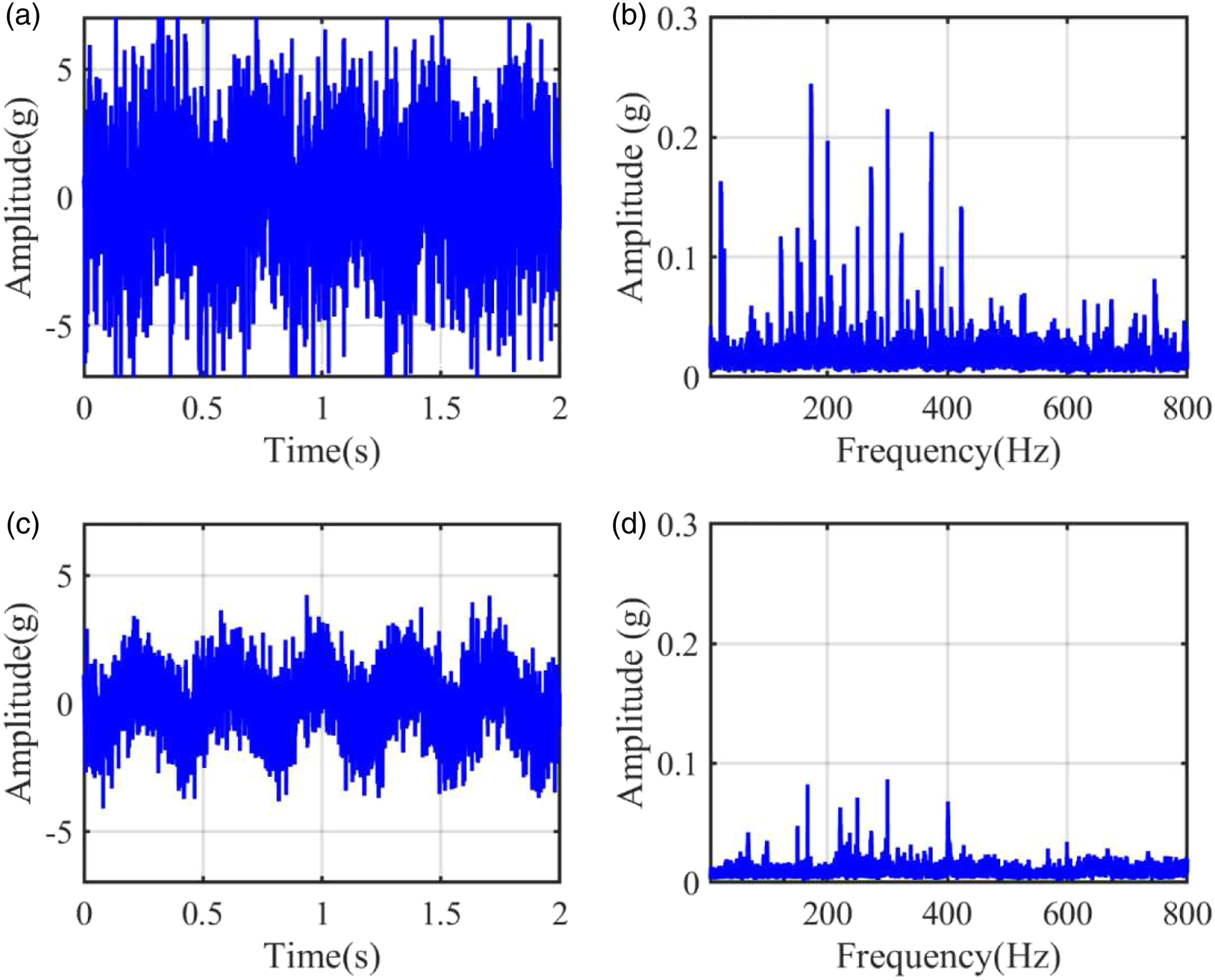
Based on the outline of the spectrum, two frequency bands are selected to extract the fault information. The frequency band from 100 Hz to 500 Hz is selected as the low-frequency band because most of the obvious elements are included in this range. The high-frequency band is selected from 500 Hz to 700H, which does not have pronounced elements but is potentially rich in fault information owing to the significant modulation phenomenon. Then, two bandpass filters were designed to obtain the low-frequency band signal and high band frequency signal. The squared envelopes of the low and high-frequency bands can be obtained by the construction of analytic signals from two orthogonal ORS outputs. Figure 6 and Figure 7 display the squared envelope spectra of the ORS vibrations from the faulty and baseline epicyclic gearboxes, respectively. Figure 6(a) and (b) show the squared envelope spectra of the low and high-frequency band signals of the faulty case, respectively. The envelope spectrum is an ensemble average of the amplitude spectra from the segmented squared envelope signals. The ensemble average increases the reliability and accuracy of the envelope analysis. The segment length in the calculation is selected as 16,384, which gives a frequency resolution of 0.1 Hz. The fine frequency resolution allows distinguishing the characteristic frequencies. The overlap ratio between segments is set as 0.7, which increases the average times for a better representation of the final result. These parameters allow 20 times average for the displayed envelope spectra. It is obvious that the compound faults can be detected in these two envelope spectra, which demonstrates the effectiveness of the ORS technique. As the faulty gearbox has three planet gears, the sub-harmonics of the characteristic sun gear fault frequency are also manifest in Figure 6(a). The characteristic frequency of the sun gear fault is dominating in the low-frequency band envelope spectrum. The envelope spectrum of the high-frequency band signal in Figure 6(b) shows that the multiple harmonics and sub-harmonics of the characteristic planet gear fault frequency are pronounced. The envelope spectra of the baseline case in Figure 7 show that the characteristic fault frequencies are nearly invisible. Envelope spectrums of ORS vibrations for faulty case: (a) in the low-frequency band and (b) in the high-frequency band. Envelope spectrums of ORS vibrations for baseline case: (a) in the low-frequency band and (b) in the high-frequency band.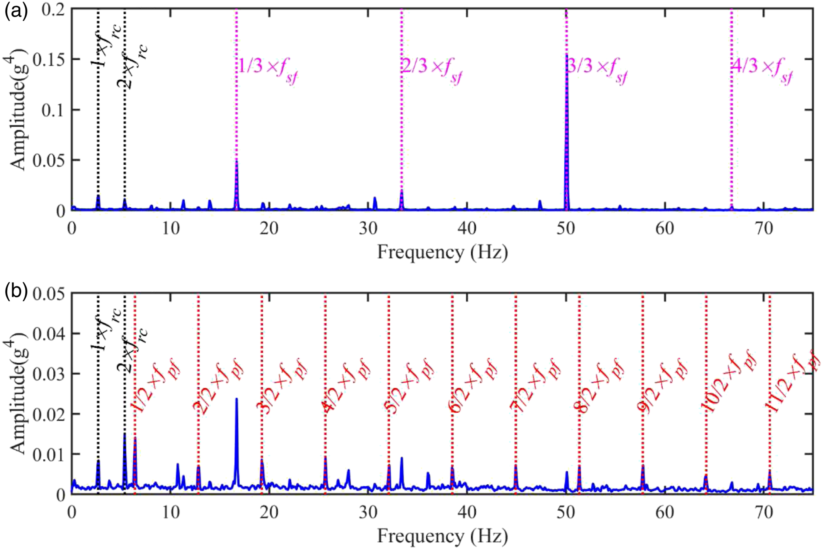
MSB Enhanced Squared Envelope analysis
Through the envelope analysis, the sun gear faults can be diagnosed. However, the signature of the planet gear faults is not pronounced and the results are mixed with some other irrelevant components. To give a more convinced and reliable representation, the MSB enhanced envelope method is used to highlight the sun and planet gear fault features. In the MSB analysis, the segment length and the overlap ratio are set the same as that in the envelope analysis, leading to equal average times. 20 times of average of MSB is not much in a noisy vibration signal analysis. A promising result of MSB relies on more average if the signal contains more random noise. Figure 8 and Figure 9 show the MSB magnitudes of the envelope from the faulty and baseline ORS measurements. As the aforementioned envelope analysis, squared envelope signals in the low-frequency band and high-frequency bands were obtained using Hilbert transform based on the manually selected two frequency bands. Two envelope signals are used as the input of the MSB method. Then the MSB results are presented in Figure 8(a) and (b), respectively. As can be observed, the fault signatures of the sun gear and planet gear can be further highlighted. The low noise carpet and strong fault features denote that the noise in the ORS vibrations is not too much because these results are obtained using only 20 times of average. For the baseline case in Figure 9, the MSB extracts some modulation components but these coupled components are not from the gear faults. MSB-ESE of ORS vibrations for faulty case: (a) in the low-frequency band and (b) in the high-frequency band. MSB-ESE of ORS vibrations for baseline case at 60% speed and 90% load: (a) in the low-frequency band and (b) in the high-frequency band.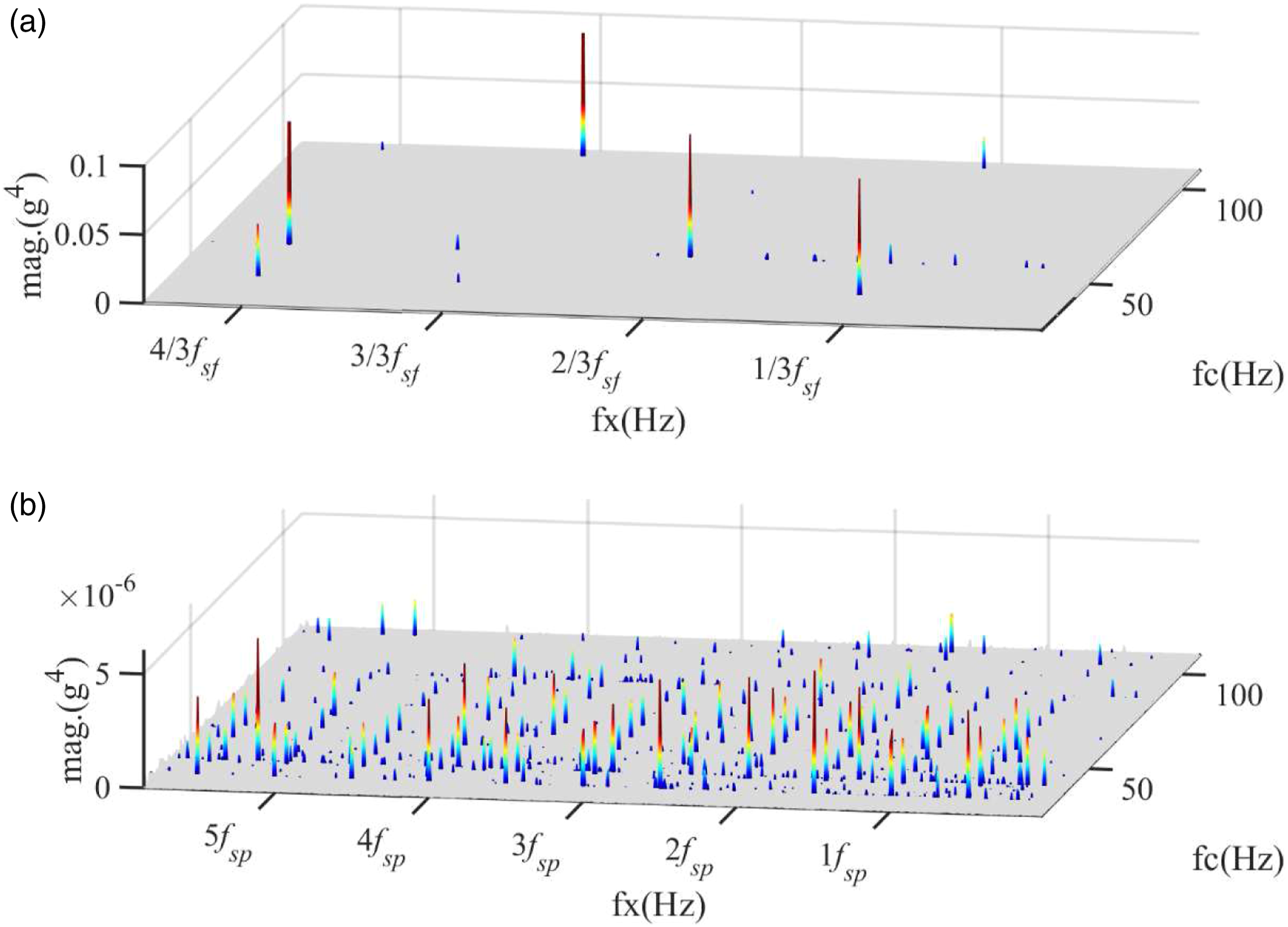
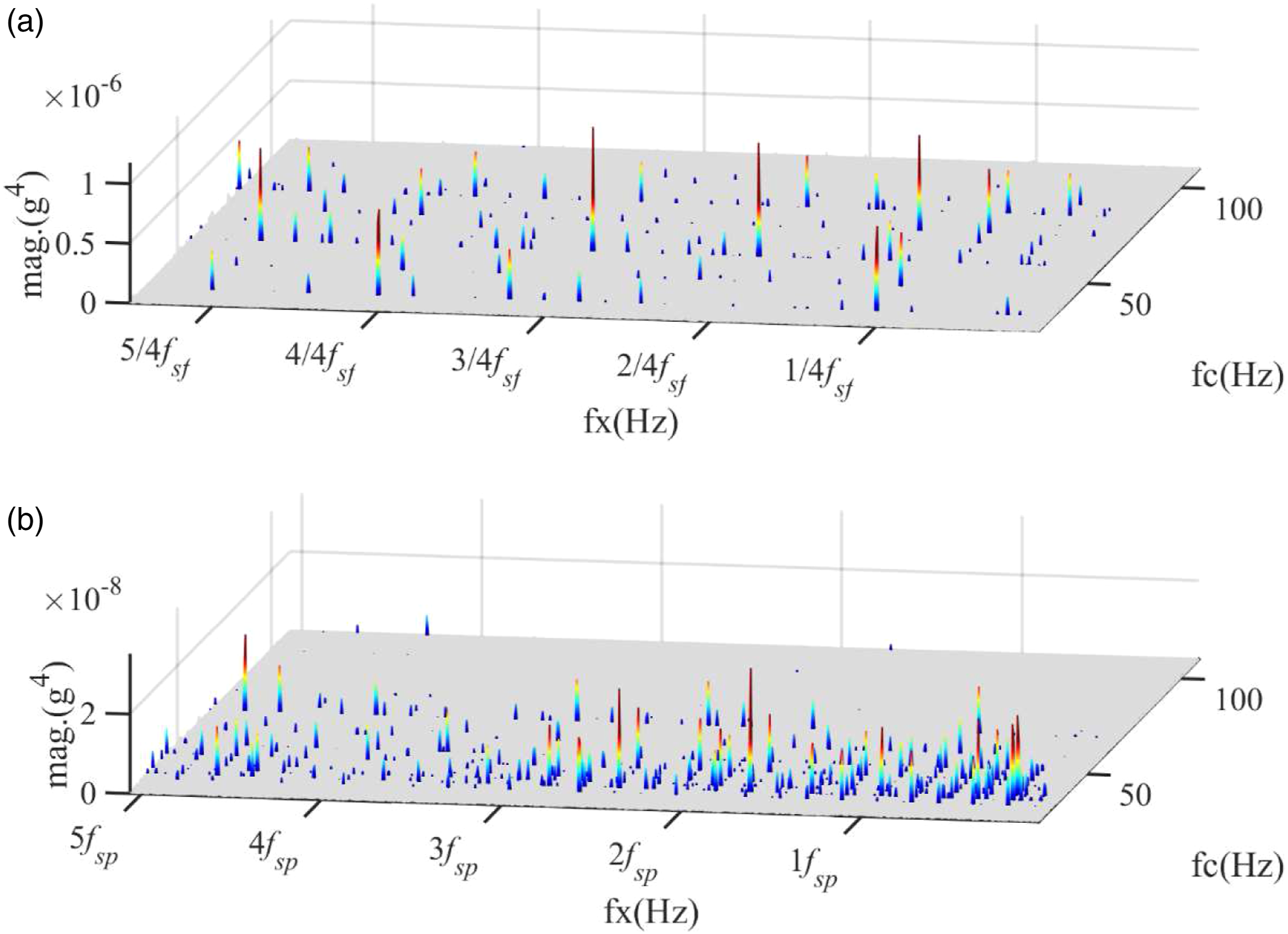
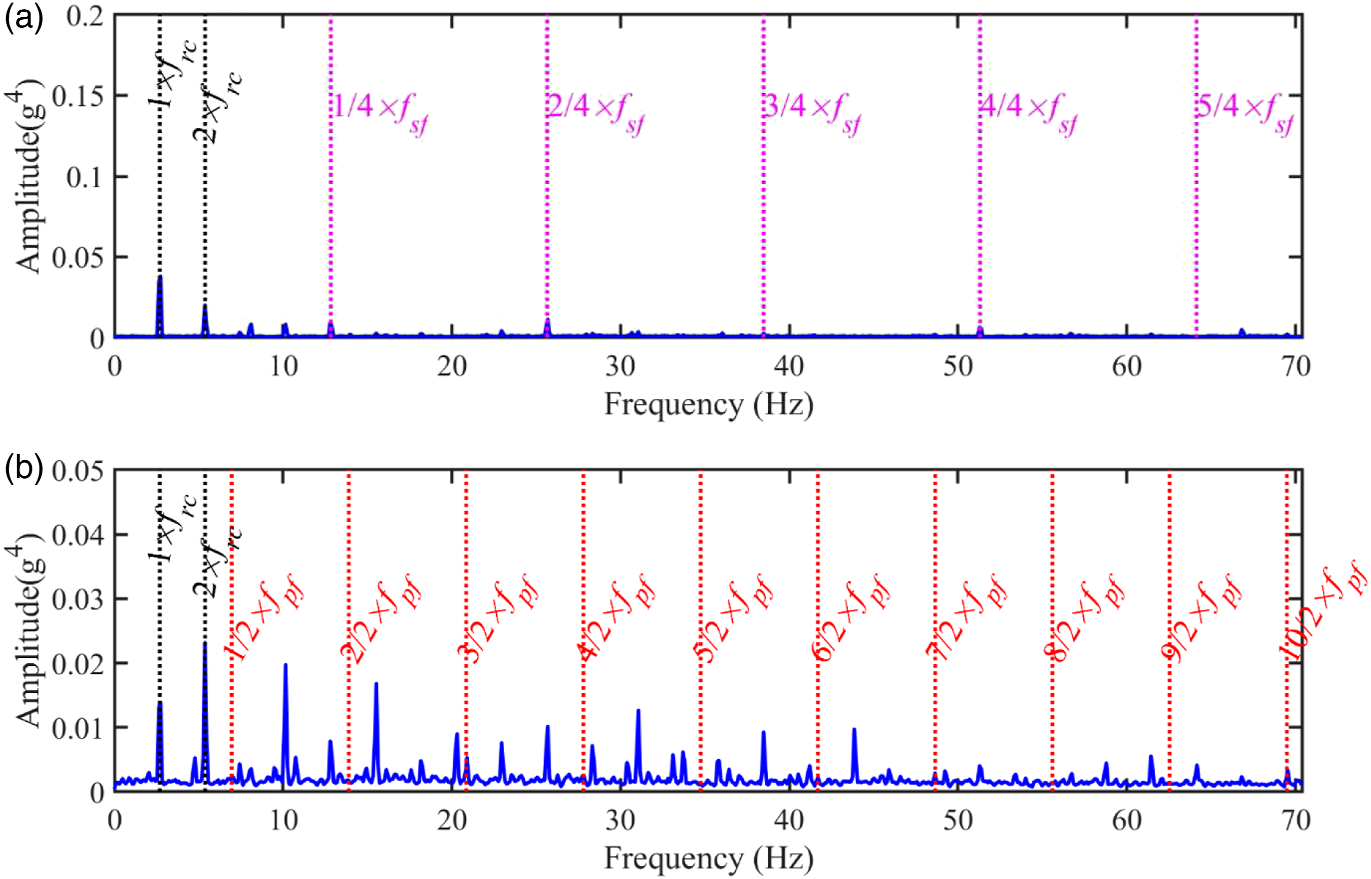
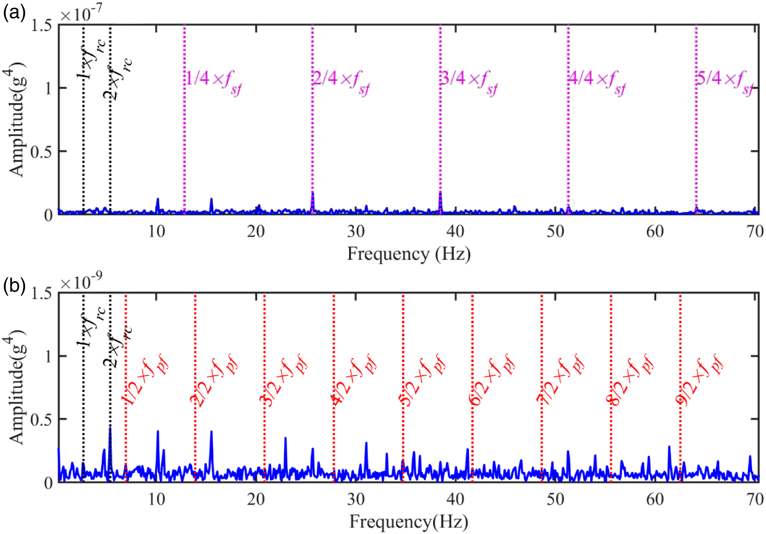
Figure 10 and Figure 11 depict the MSB-ESE of the faulty and baseline cases, respectively. As shown in Figure 10(a), the sub-harmonics of the characteristic sun gear fault frequency are pronounced, and the dominating component is the sun gear fault frequency. Figure 10(b) gives a much better diagnosis result than that of the envelope analysis. The sub-harmonics and harmonics of the characteristic planet gear fault frequency are highlighted in the MSB-ESE whilst the other uncorrelated components are significantly suppressed. To verify the diagnostic results, the MSB-ESE of the ORS vibrations from the baseline case is shown in Figure 11. The baseline epicyclic gearbox works in a smooth and good condition, and consequently, the characteristic fault frequencies are about 10 thousand smaller than the faulty one in the MSB-ESE (refer to the Appendix 1 for more results at the other five working conditions). MSB-ESE of ORS vibrations for the faulty case at 60% speed and 90% load: (a) in the low-frequency band and (b) in the high-frequency band. MSB-ESE of ORS vibrations for baseline case at 60% speed and 90% load: (a) in the low-frequency band and (b) in the high-frequency band.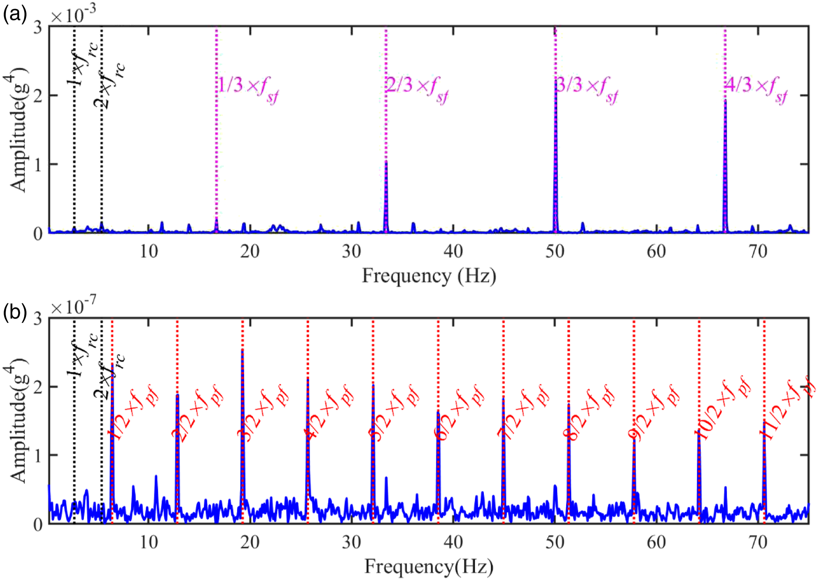
To show the effectiveness of the proposed MSB-ESE, the spectra using on-housing vibrations are also calculated, which is shown in Figure 12. It can be seen that the proposed method is also effective to obtain the sun gear and planet gear fault features. However, due to the intricate modulation, the sidebands f
rc
around the sun gear fault frequency f
sf
are also obvious. This result shows the effectiveness of the proposed MSB-ESE method and it also shows that ORS vibrations are much less influenced by transmission path. MSB-ESE of housing vibrations for faulty case: (a) in the low-frequency band and (b) in the high-frequency band.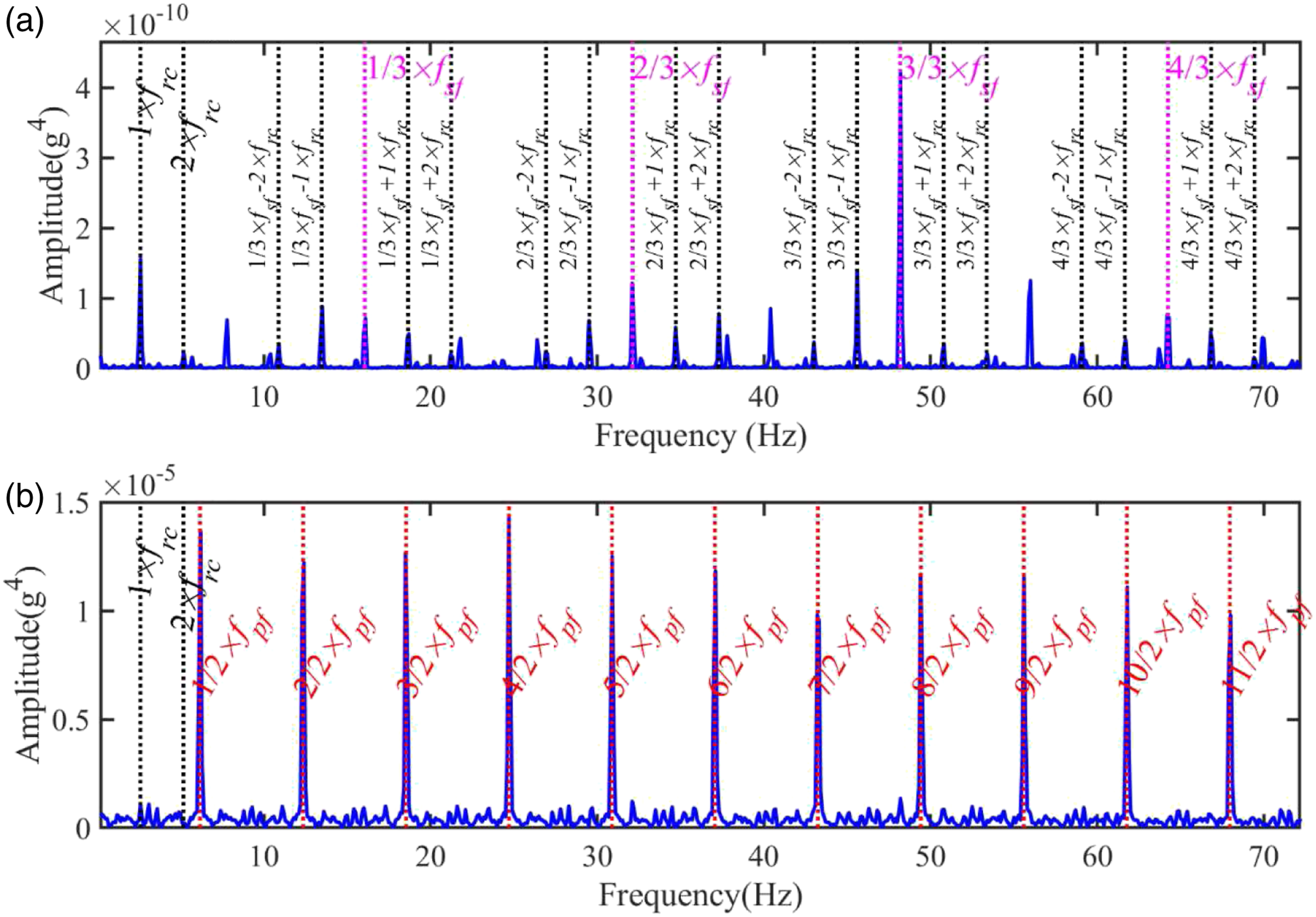
Spectral Correlation Enhanced Envelope Spectrum
To further highlight the proposed method, the Spectral Correlation Enhanced Envelope Spectrum is also explored because it can better enhance the non-zero cyclic components.
33
The Spectral Correlation Enhanced Envelope Spectrum is defined based on the Spectral Coherence which yields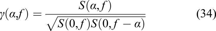
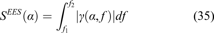
Figure 13 shows the Spectral Correlation Enhanced Envelope Spectrum for the faulty case and it can be seen that the results are similar to the conventional squared envelope spectrum as presented in Figure 6. The sun gear fault can be identified clearly. However, the planet gear fault can be observed but mixed with other irrelevant components because of its noise inclusion and other interference. The fault frequencies and harmonics cannot be isolated from multiple discrete components and produce less reliable diagnostics. Spectral Correlation Enhanced Envelope Spectrum of ORS vibrations for the faulty case at 60% speed and 90% load: (a) in the low-frequency band and (b) in the high-frequency band.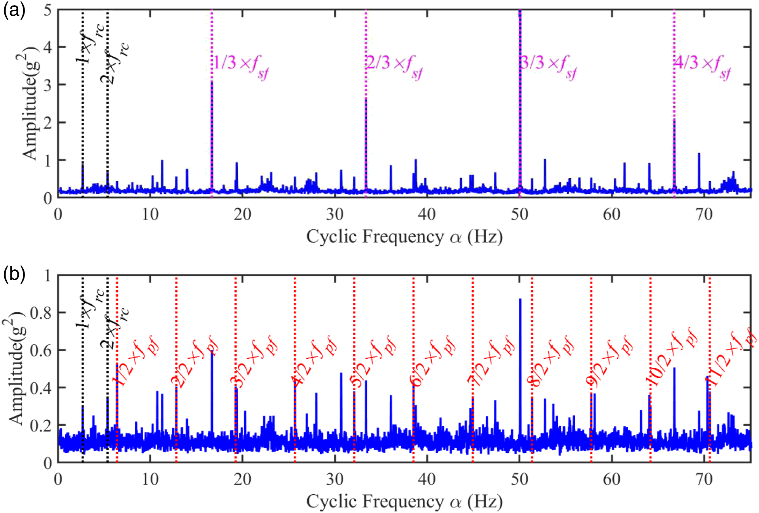
Conclusions
To avoid the deficiency of conventional on-housing vibration measurements and analysis, this paper proposed a Modulation Signal Bispectrum Enhanced Squared Envelope method to extract the multiple fault harmonics in squared envelope analysis of vibration signals from a special ORS sensor on the carrier shaft of an epicyclic gearbox. The time-varying paths can be avoided by the ORS measurements and the MSB-ESE method can enhance the numerous fault harmonics induced by localised faults and suppress inevitable background noise in the squared envelope. The experimental studies demonstrate that the novel MSB-ESE can achieve a reliable diagnosis of compound planet and sun gear faults. In addition, this systematic sensing and analysis method can be used widely in condition monitoring of other rotating machines.
Footnotes
Acknowledgements
The authors would like to express their appreciation to the Centre for Efficiency and Performance Engineering (CEPE) at the University of Huddersfield for supporting the accomplishment of this research.
Declaration of Conflicting Interests
The author(s) declared no potential conflicts of interest with respect to the research, authorship, and/or publication of this article.
Funding
The author(s) received no financial support for the research, authorship, and/or publication of this article.
Appendix
MSB-ESE of ORS vibrations at speed 60% and load 75% for the faulty case: (a) in the low-frequency band and (b) in the high-frequency band.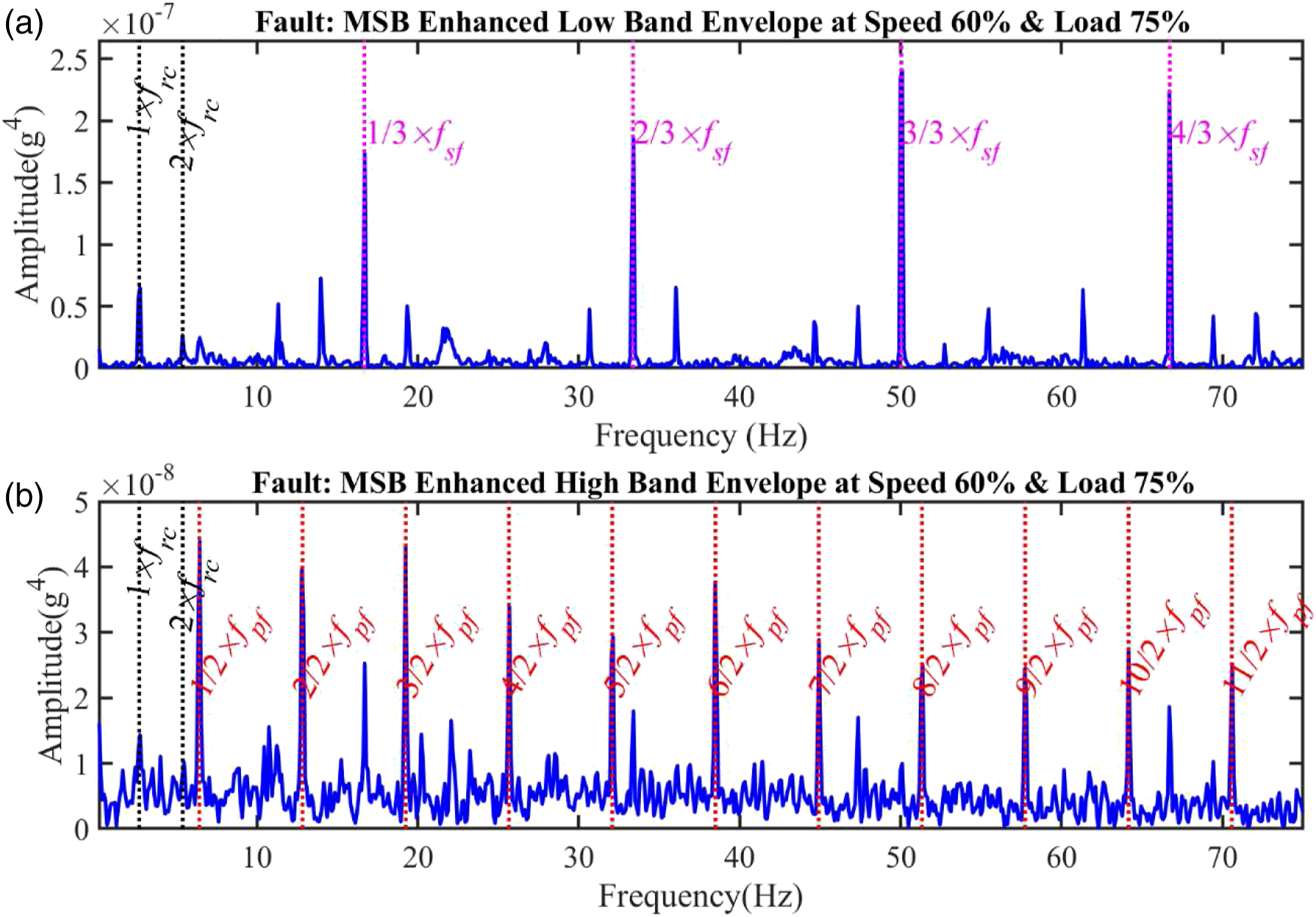
MSB-ESE of ORS vibrations at speed 60% and load 50% for the faulty case: (a) in the low-frequency band and (b) in the high-frequency band.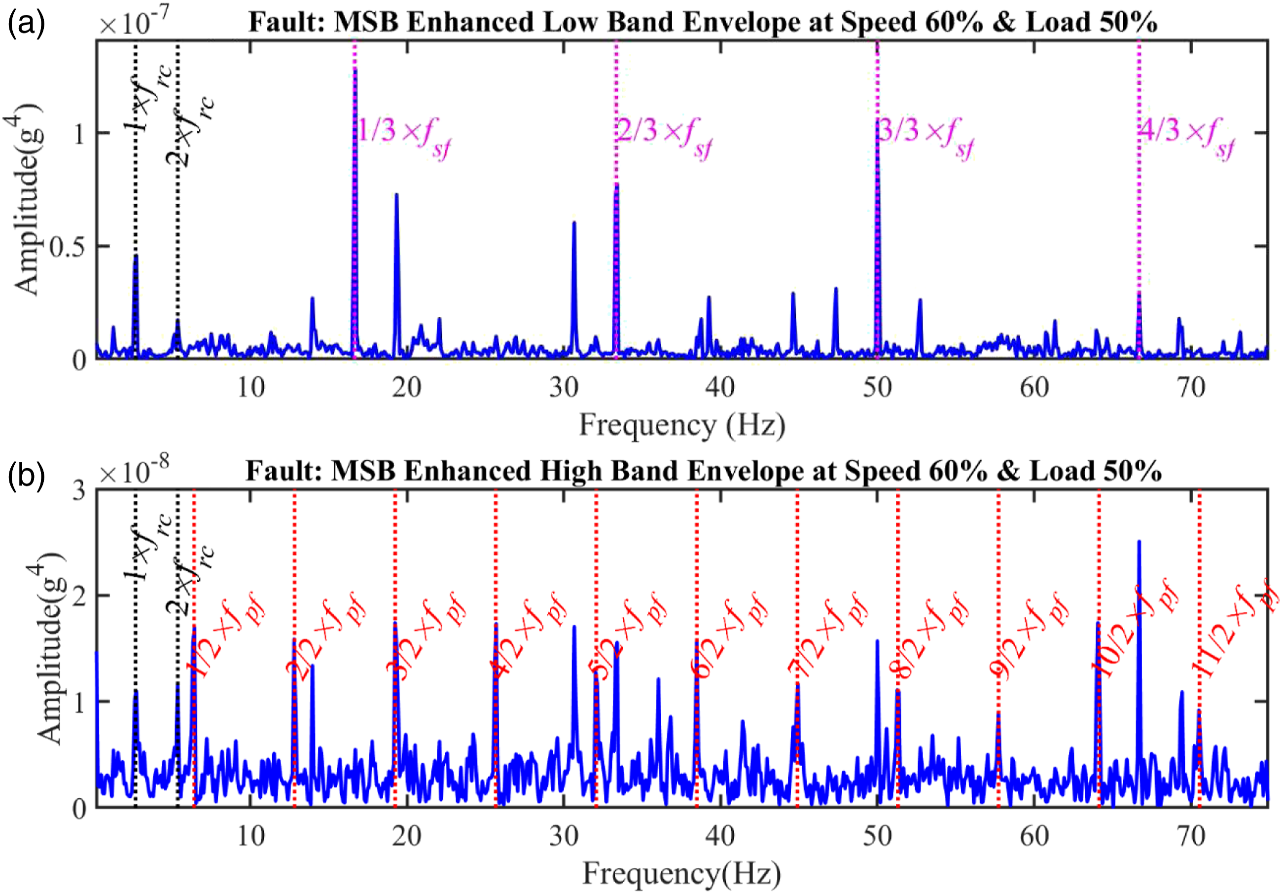
MSB-ESE of ORS vibrations at speed 40% and load 90% for the faulty case: (a) in the low-frequency band and (b) in the high-frequency band.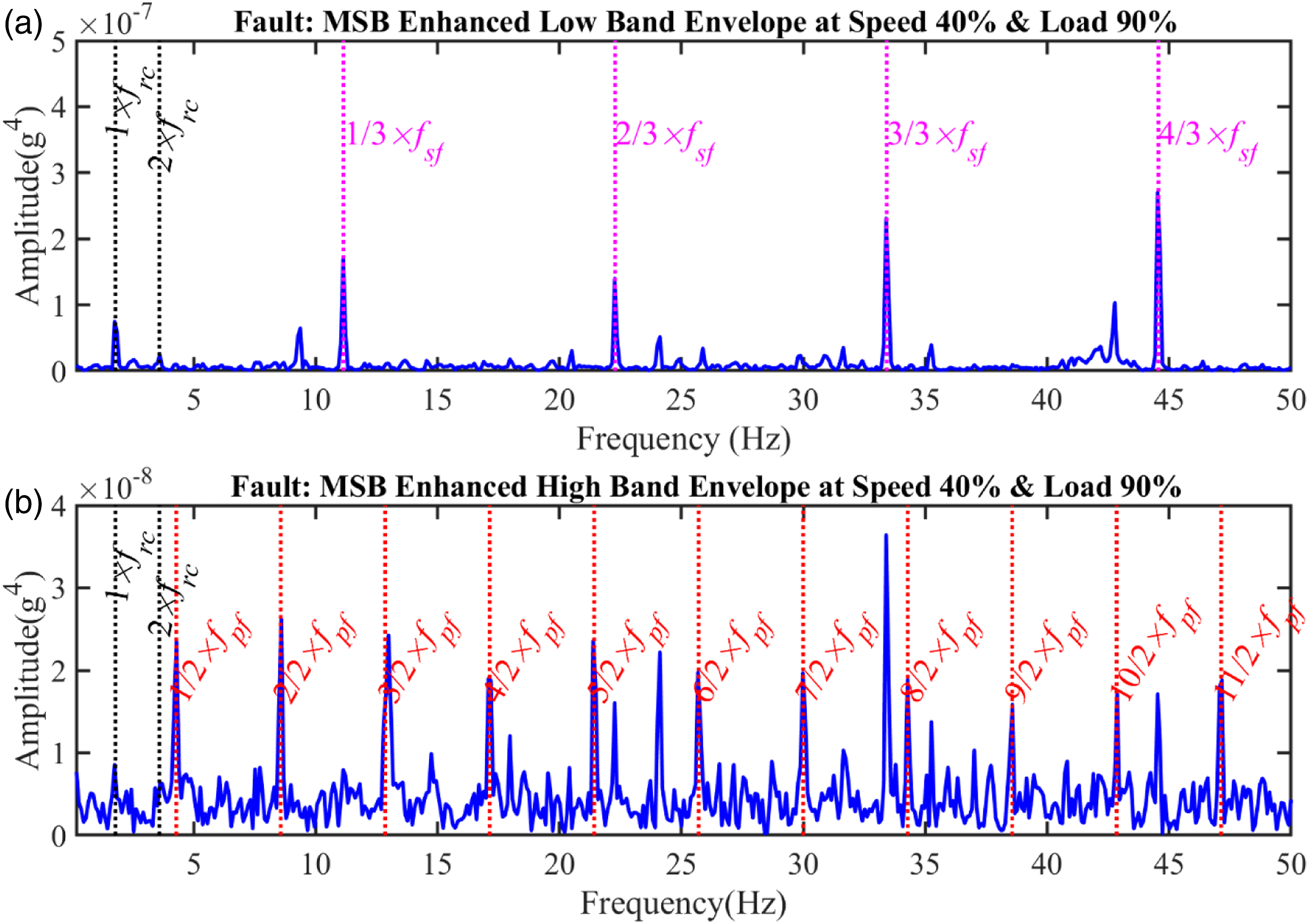
MSB-ESE of ORS vibrations at speed 40% and load 75% for the faulty case: (a) in the low-frequency band and (b) in the high-frequency band.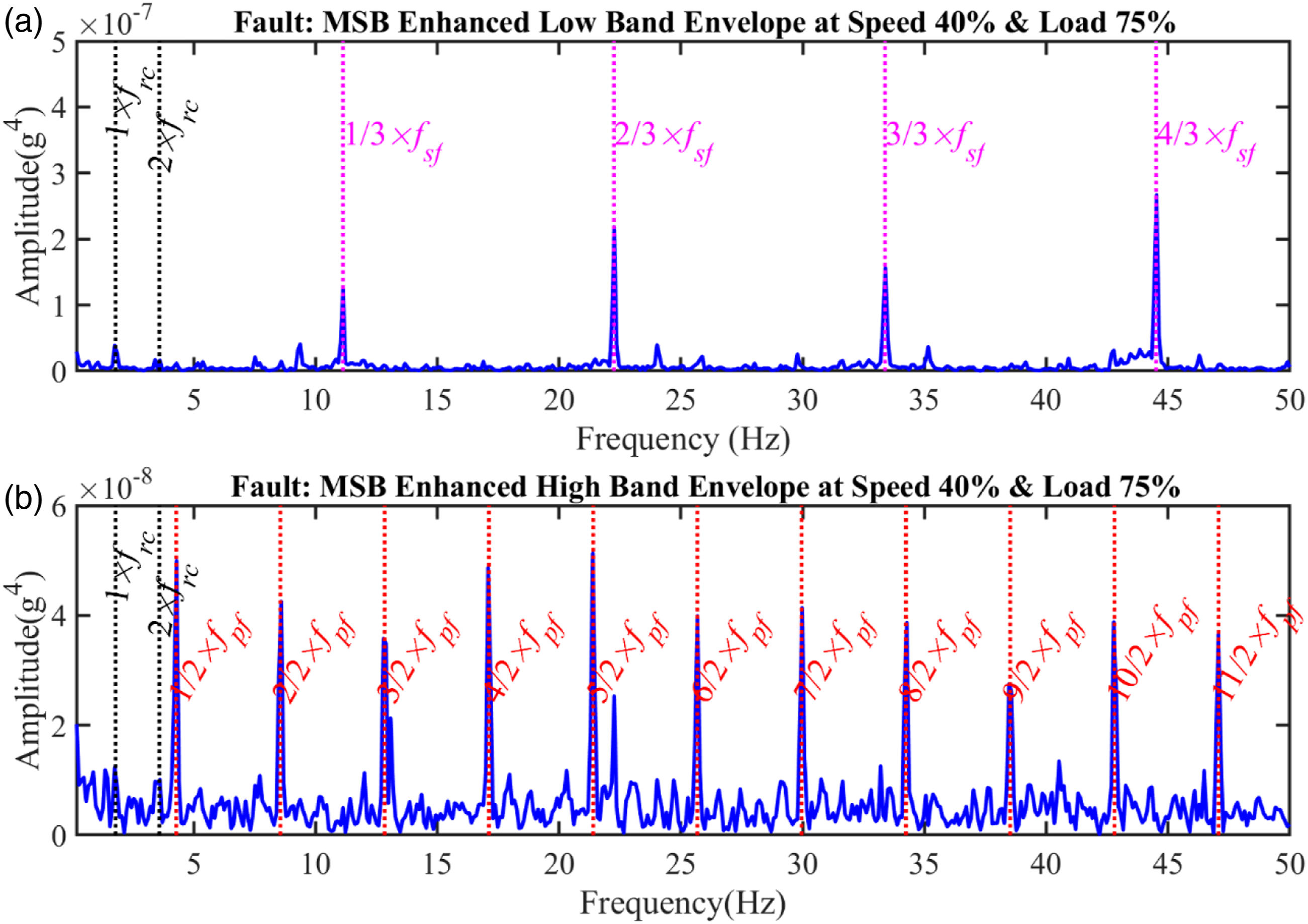
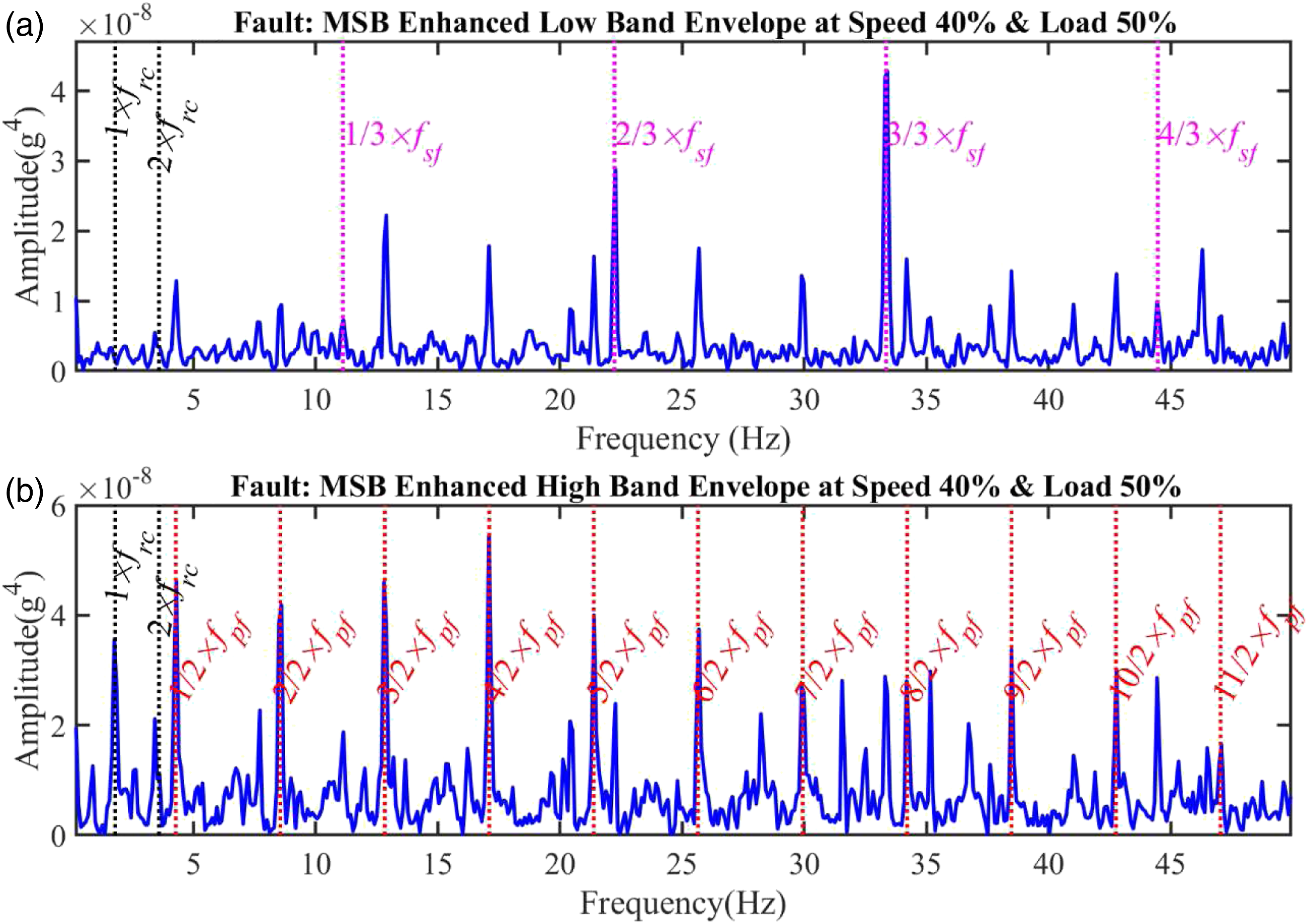
MSB-ESE of ORS vibrations at speed 40% and load 50% for the faulty case: (a) in the low-frequency band and (b) in the high-frequency band.