
Abstract
Variations in environmental conditions can significantly impair the accuracy and reliability of guided wave structural health monitoring systems. Acquisition of baseline signals over a wide temperature range for the purposes of damage detection and localization is impractical for large composite structures. A novel framework for compensating the effect of temperature at a post-processing stage is presented in this paper to allow updating the compensation factors using observations obtained at different scales. The proposed methodology utilizes observations collected at the lower scales, where a large amount of data under controlled environment is available. Subsequently, the estimated compensation factors are propagated to the higher scales as priors within a Bayesian framework. This way, the measurements required from the high levels are reduced while making it possible to also update the estimated factors during the operation of the structure. The performance of the methodology is evaluated at different scales and compared with the direct use of compensation factors obtained from coupon studies only. It is demonstrated that the proposed methodology improves the fidelity of the compensation algorithm leading to a reduction in the uncertainty of the temperature-compensated signals. Based on the findings of the present study, the reduction in the uncertainty of the compensation improves the performance of both damage detection as well as damage localization in a large composite panel.
Keywords
Introduction
In recent years, composite materials are the subject of many research studies in the aviation industry due to their excellent stiffness to weight ratio.1,2 Composites however are prone to low velocity impact damage that can significantly affect the reliability of the structure and lead to catastrophic failures. Structural health monitoring (SHM) strategies have gained attention as an option for the integrity assessment of a structure. Contrary to traditional non-destructive inspection (NDI) techniques, SHM systems are able to interrogate the structure over long distances, minimize manual labor and human intervention, and allow the transition from the current practices of schedule-based maintenance to a condition-based maintenance philosophy.3–5 There still are challenges that need to be overcome prior the industrial adoption of SHM in aviation. These challenges can be traced back to the geometrical complexity of aircraft structures, plethora of damage scenarios in composites, cost-benefit limitations, and the wide range of the aircraft environmental and operational conditions (EOC).6–8
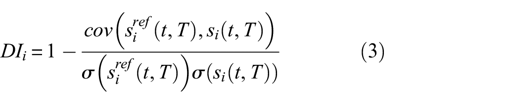
Guided wave–based SHM (GWSHM) systems utilize a network of piezoelectric transducers (PZTs) that can be permanently mounted on or embedded into the structure. Numerous studies have demonstrated that such systems are capable of detecting and localizing barely visible impact damage (BVID) in composite materials.2,9–13 Typical GWSHM systems are based on the comparison between a baseline measurement that has been taken from a known system state that is considered pristine or defect-free, with a current measurement whose state is unknown. Such systems have been proven effective for complex structures as the baseline and the current measurements already include effects such as geometry and material variability. 14 During this comparison, damage sensitive features are extracted such as time of flight, amplitude, and phase change which provide the basis for damage indexes (DI), for the detection and the localization of defects.10,15–17
The existence of damage will cause a significant increase in the damage indexes of the sensor pairs in its vicinity. However, non-zero values of
Treatment of the variability in the structure’s temperature during the lifetime of an aircraft is a major challenge. Temperature difference between the baseline and a current signal can impair the damage detectability and lead to unacceptably high false positive readings. 24 Therefore, it is crucial to adopt a form of temperature compensation to improve the diagnostic reliability of a GWSHM system considering its in-service conditions. 22 Various temperature compensation methodologies have been reported in the literature to reduce the effects of temperature difference. The optimal baseline selection (OBS) methodology 23 attempts to find a best match between the current signal and a pre-recorded dataset of baseline signals, taken at different temperatures. Another popular methodology is the baseline signal stretching (BSS) that is contrary to OBS does not require a large database of pre-recorded signals. 25 Using BSS, the baseline signal is stretched to match the current signal while the optimal stretch factor is obtained iteratively based on minimization criteria. However, the applicability of the method is limited to a specific temperature range. Combinations of the OBS and BSS approaches have also been proposed to reduce the signals required for the construction of the baseline database considering the BSS temperature range.24–26 Other attempts follow data-driven routes to achieve temperature compensation. For instance, in Ref. 27, two baseline signals, recorded at different temperatures, are used to reconstruct a baseline at the current temperature while in Ref. 28, a regression model is implemented to describe the phase and amplitude variations in guided waves under different temperatures. In a recent study, 22 a regression model was also used to model the temperature variation of the phase and amplitude compensation factors based on measurements on a composite coupon. It was also demonstrated that the compensation factors extracted from a coupon can be applied to more complex structures and mitigate the effects of temperature difference.
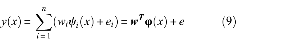
Many of these methodologies require the collection of a large dataset of baseline signals or obtaining baseline recordings at specific temperatures. Although this might be possible in a laboratory for simple coupons and smaller components, it can be infeasible for large-scale structures.22,25 In the aviation industry, the design, development, and validation of a GWSHM system starts at small scale demonstrators (e.g., coupons) and follows the building block approach for aircraft design, 29 where at each level, the scale and the complexity of the structure increases. The objectives of the proposed framework are (i) reduce the number of baseline signals required from large-scale components, (ii) account for the structural complexities of the target structure based on measurements taken from the lower scales, (iii) allow for the updating of the estimated compensation factors as more signals become available (e.g., during operation), and (iv) improve the reliability of the temperature compensation method as the structure’s complexity increases. These objectives are desirable attributes for the industrial adoption of GWSHM systems. This study builds upon two main contributions to propose a novel framework for the propagation and the refinement of temperature compensation information moving through the scales. More specifically, in Ref [9], the development of the detection and localization algorithms for large composite structures is presented following the building block approach. Sensor path eligibility criteria are established to ensure that the signals across the different scales are similar. Furthermore, in Ref [22], a data-driven temperature compensation methodology is presented that estimates the compensation factors along different propagation directions using measurements taken from a coupon. In the proposed framework, the temperature compensation factors obtained at the lowest scale (coupon) are used as a starting point and a novel up-scaling methodology is described that introduces additional corrections factors to improve temperature compensation. The purpose of the correction factors is to account for the effect of the structural complexities (such as stringers and different geometry.) that have not been considered. The correction factors introduced are propagated through the scales within a Bayesian regression model. 30 The introduction of the Bayesian model allows to use the observations obtained at a previous scale as prior information for the current scale as well as update the current correction factors when new observations become available. Therefore, a rigorous methodology is established that informs the higher scales based on the observations of the lower scales capable of reducing the required number of large-scale experiments required.
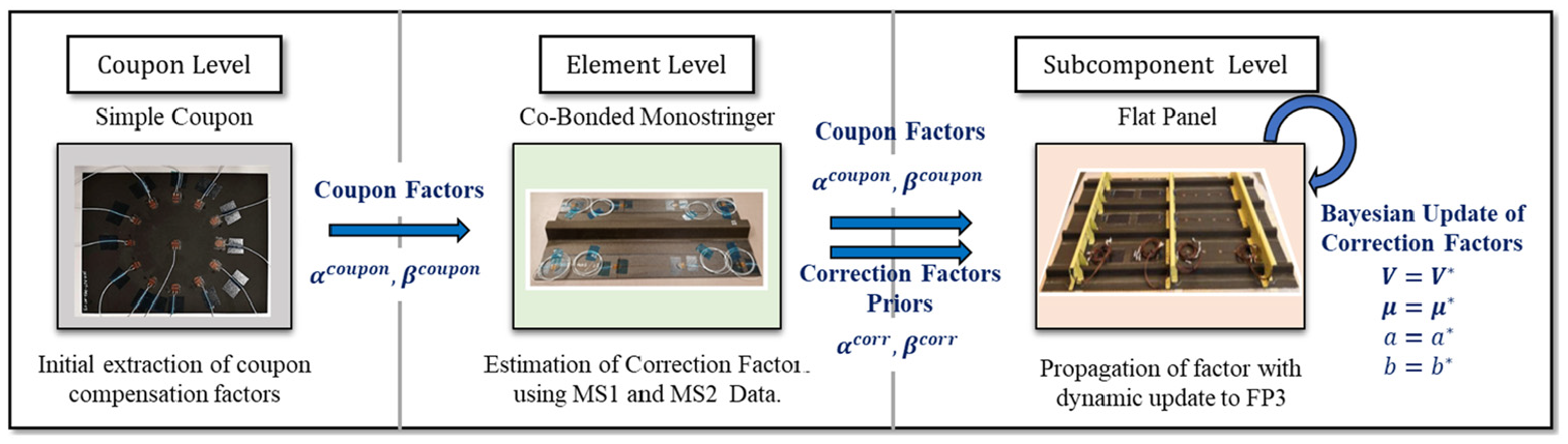
The proposed information passing between the different scales is illustrated in Figure 1. A case study is adopted in to demonstrate the methodology. A 1.6 m long flat stiffened panel is considered as the final scale target structure and the aim is to obtain the temperature compensation factors to improve damage detectability and localization for typical aircraft EOC. This scenario presents a case where obtaining baseline measurements from the target structure over a wide range of temperatures might be infeasible. This restriction can be alleviated by exploiting measurements taken from lower scales. Through this case study, the process of transferring observations from the lower scales to the higher ones is exemplified. At the lowest scale (coupon), temperature compensation factors are extracted along different directions. A 0.5 m long monostringer is used as an intermediate scale to introduce geometrical complexities in the estimation of the compensations factors that are found in the flat panel scale but are missing from the coupon scale. Although a single intermediate scale is used here, the methodology is applicable to situations where multiple intermediate scales are needed. All specimens are manufactured using the same layered composite material that exhibits anisotropic behavior. Due to the Bayesian nature of the regression model, it is also possible to update the estimated correction factors within each scale if new measurements become available.
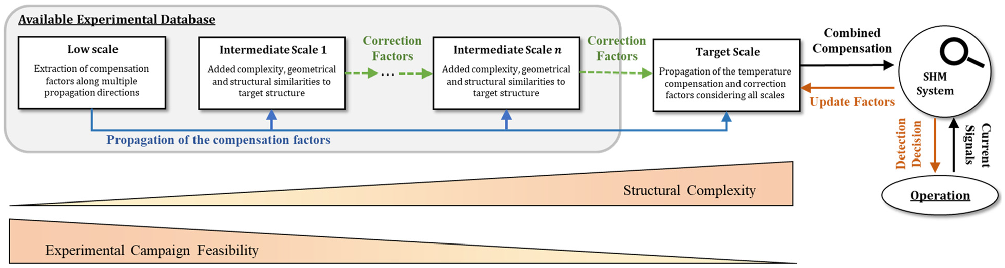
Propagation of information within the proposed temperature compensation framework.
This contribution is structured as follows: the Methodology section presents the methodology adopted for the proposed framework and contains details of the experiment set-up used, the extraction of the compensation factors, and the Bayesian regression model. In the section Comparison of the Temperature Compensation Methods, the performance of the proposed temperature compensation framework is demonstrated based on measurements obtained at the element and the sub-component level. Then, in the Damage Detectability and Localization Results section, the improvement in terms of defect detectability and localization accuracy is demonstrated when the baseline and the current signals are obtained at different temperatures.
Methodology
Experimental set-up and signal processing
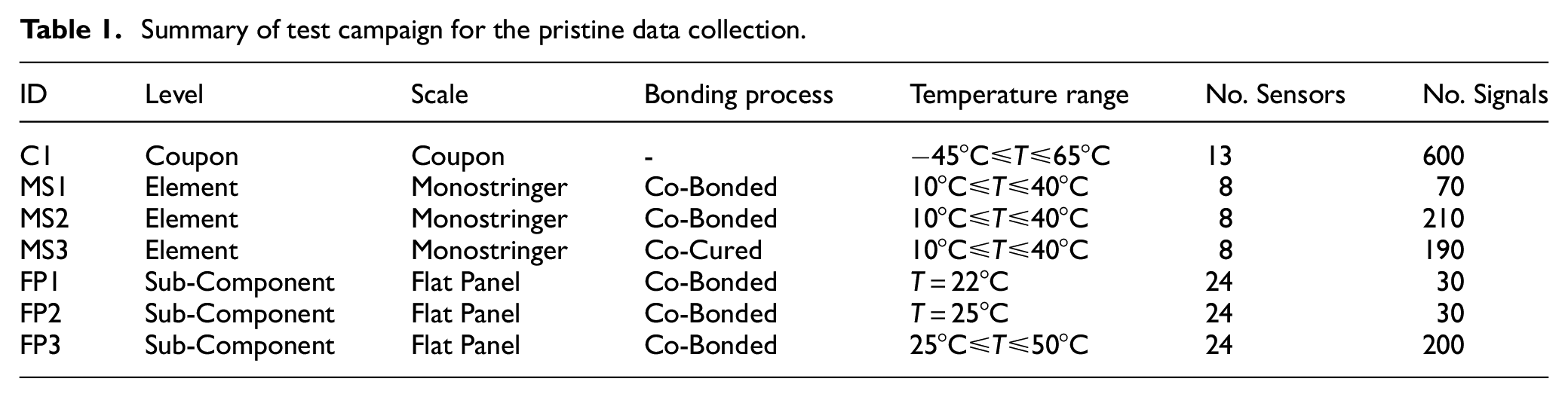
Guided wave measurements are collected from a series of composite structures under different temperatures. All specimens are made of thermoset M21/194/34%/T800S unidirectional prepreg material with stacking sequence
where
To obtain measurements under different EOC, a TVC J2235 environmental chamber is used. Measurements are collected over a range of temperatures, with a step of
Summary of test campaign for the pristine data collection.
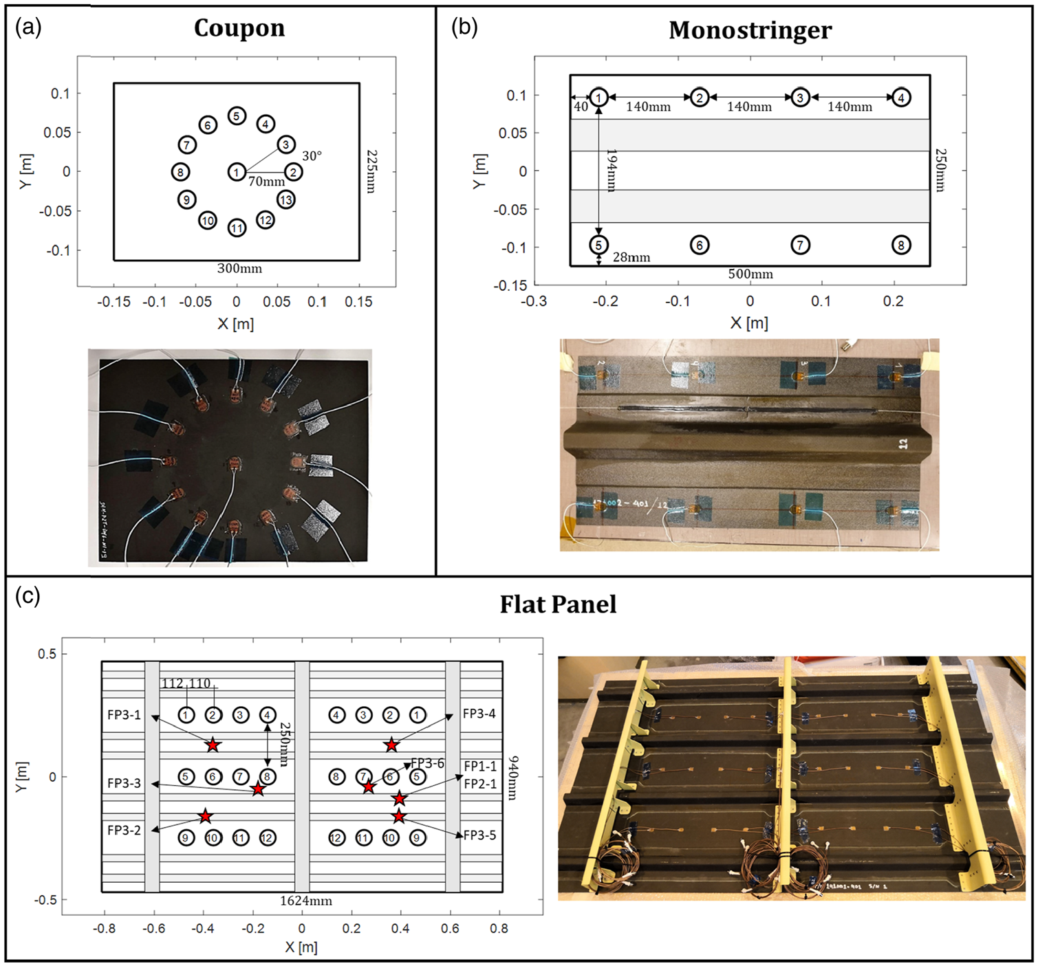
Geometry and sensor locations for a) coupon, b) monostringer, and c) flat panel. Red stars in the flat panel indicate the locations of the impact events.
The behavior of propagating guided waves can be significantly affected by the structural complexities of large structures (e.g., pair distance and number of stiffeners). In such scenarios, the signal might experience excessive attenuation and wavemode conversion making the comparison with lower scales difficult. To allow up-scaling of the compensation algorithm, the sensor pair eligibility criteria set out in Ref [9] are adopted. Eligible pairs must offer additional coverage (i.e., path
Let
Let

where
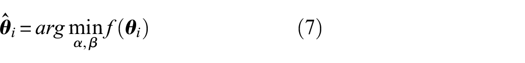
Damage detection and localization can be carried out by comparing two signals: the first signal is a reference signal
where
Due to the anisotropic behavior of the composite material, the wave propagation direction influences the characteristics of the signal. The propagation direction,
Temperature compensation and extraction of correction factors
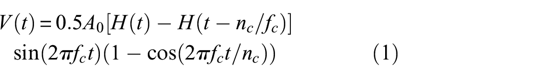
The effect of temperature difference on the recorded guided wave signals can be approximated using the following expression22,35

where
In Ref [22], the temperature compensation factors were estimated based on coupon measurements following a data-driven approach. It was demonstrated that these factors can be treated as material properties and although computed from simple coupons, can be used to mitigate the effects of temperature difference at complex structures. The efficiency of the compensation can be further improved by accounting for structural complexities (e.g., stringers) of the host structure. The coupon scale compensation factors are taken from Ref [22] directly while this study focuses on applying corrections to higher scales.
The temperature compensation factors can be written as


where
Due to the complex interaction of temperature with the wave propagation characteristics, a data-driven approach based on experimental measurements taken at different temperatures is implemented to estimate the optimum
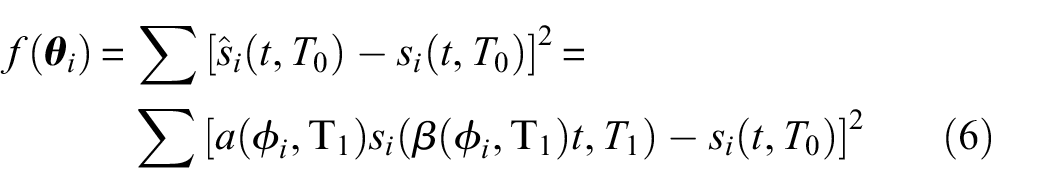
where
Based on the results presented in Ref [22], the constrains


As an example, the temperature compensation for two different sensor pairs of FP3 is illustrated in Figure 3. A signal that is measured at
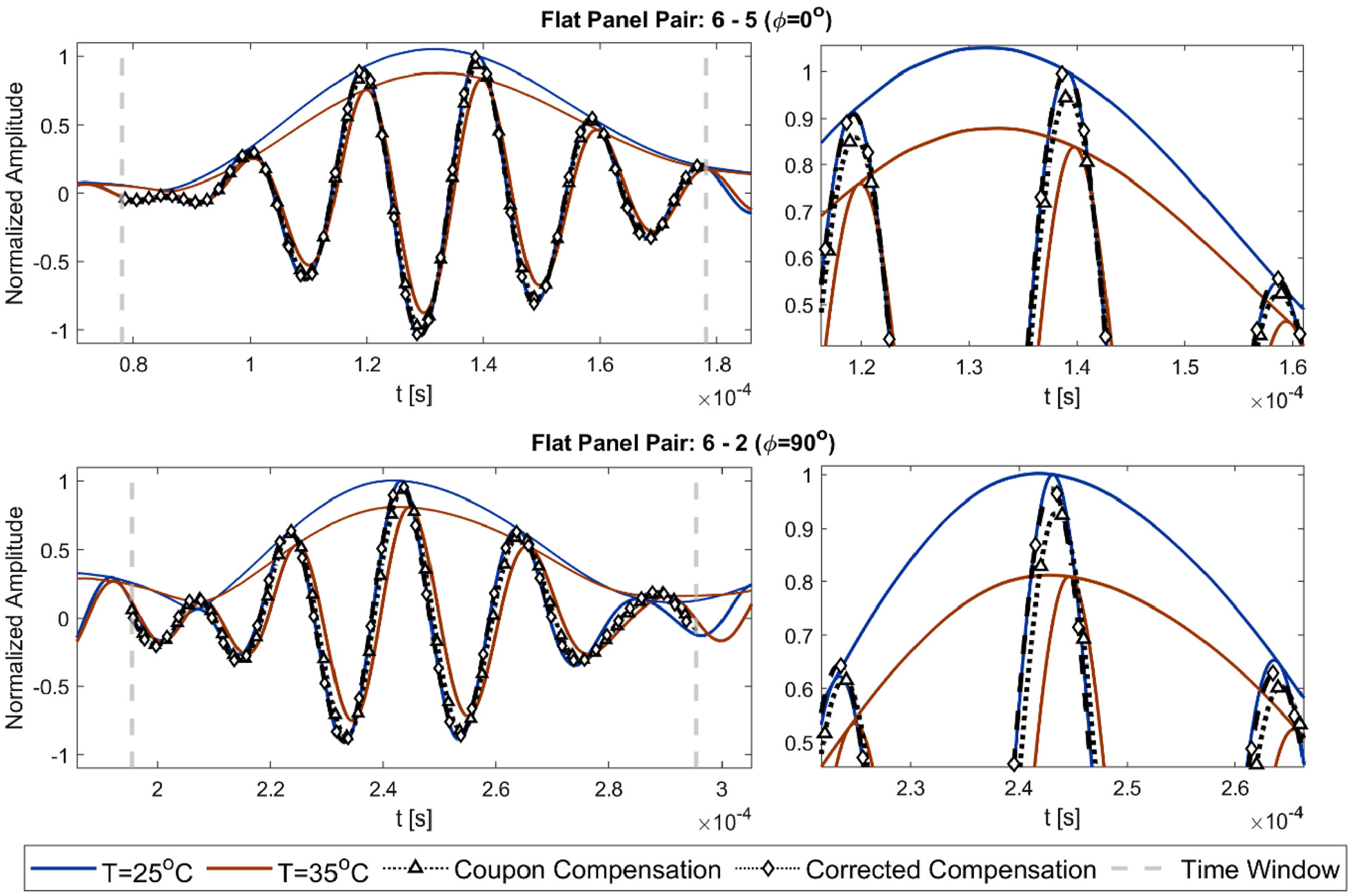
Comparison of the compensation performance when the coupon and the corrected compensation factors are used along propagation directions
To evaluate the effect of uncertainty in the estimation of the time window (see equation (2)), on the estimation of the compensation factors, the arrival time
Estimated
Bayesian regression model with radial basis functions
The use of the Bayesian inference can provide the mathematical foundations for refining prior information and accounting for uncertainties. 37 An impediment of the common compensation approaches is the difficulty to collect the large number of data required in real large-scale structures. The introduction of a Bayesian regression model in the proposed framework allows to propagate the information from the lower to the higher scales in the form of priors as well update the correction factors as new observations become available (e.g., during the operation of the aircraft).
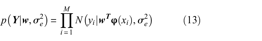
The correction factors are modeled using a linear regression approximation 30
where
where
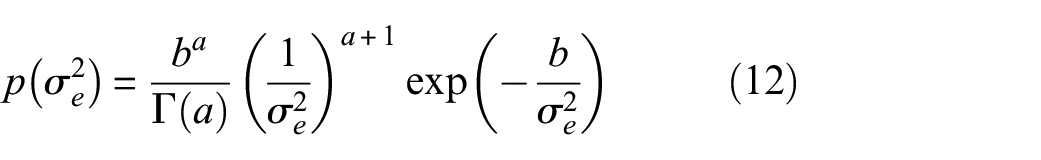
For the Bayesian treatment of the linear regression model, conjugate priors are selected that allow all expressions to be solved in closed form.
40
It is assumed that both the weights
where
where
For a dataset of
Since the NIG prior is a conjugate family for the regression problem, the posterior is also NIG distributed as

where
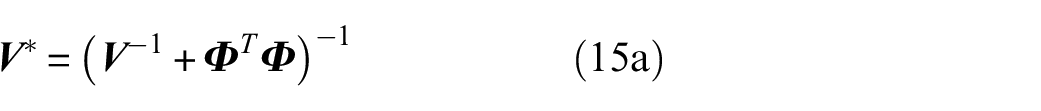


where
Predictions at a new set of inputs
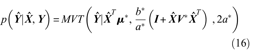
where
Damage detection and localization method
Adoption of an appropriate methodology and the selection of a threshold value are required to reliably distinguish between pristine and damaged signals. In this study, the methodology presented in Ref [9] and briefly described here is adopted to demonstrate potential improvements in terms of damage detectability when the proposed temperature compensation framework is employed. This detection method is selected as it follows the sensor adaptation, allowing the transition between different scales.
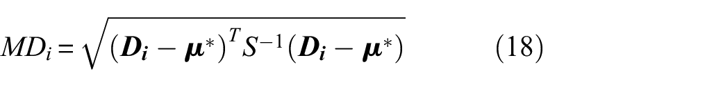
The damage detection methodology is based on computing
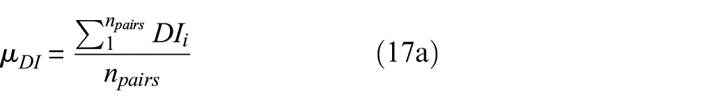
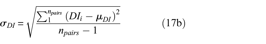
The values computed from equations (17a) and (17b) are stored in the vector
where
Damage localization is also an integral part of a GWSHM system as it can provide valuable information regarding the damage location. The damage localization algorithm is executed after the damage detection has indicated the existence of damage. Details on the localization imaging used are included in Appendix A.
Comparison of the temperature compensation methods
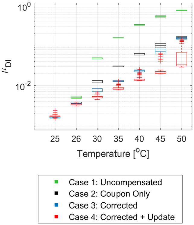
One of the drawbacks of the data-driven methods is the requirement of multiple measurements to estimate the compensation factors. The capability of the proposed framework to propagate and improve the accuracy of the temperature compensation algorithm is demonstrated in this section. For comparison between different compensation options, the following cases are presented:
Case 1: No compensation is applied to the signals. This case is included for benchmarking purposes.
Case 2: Temperature compensation I carried out using only the factors extracted from the coupon data. Information is passed from the coupon scale to the current scale directly.
Case 3: The correction factors computed from the previous scales are also considered. In this setting, information is passed from the lower to the higher scales. Case 2 is the starting point for Case 3.
Case 4: The correction factors that have been passed on by the lower scales are updated in the current scale as new observations become available. Thus, Case 3 provides the starting point for Case 4.
Monostringer scale
As a first example, the measurements collected from the monostringers are used to demonstrate the potential performance gain of introducing the correction factors for the temperature compensation. In this example, a baseline pristine signal, measured at
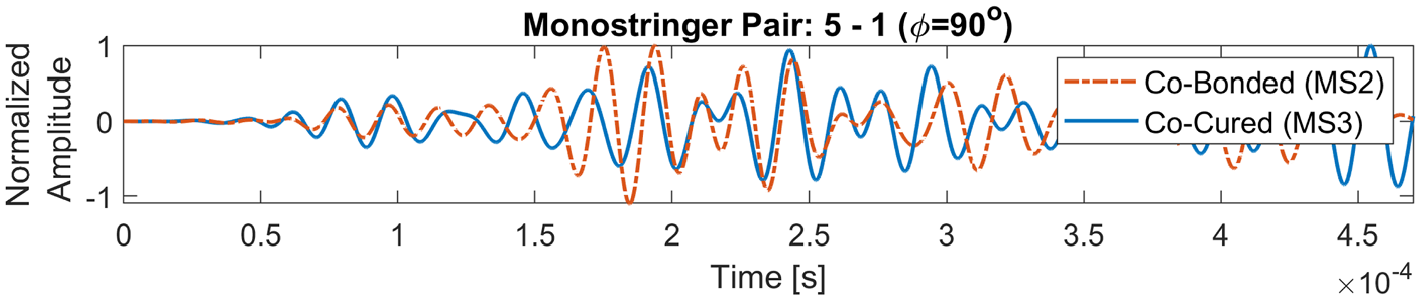
Comparison of signals between a co-bonded (MS2) and a co-cured (MS3) monostringer. The path illustrated crosses the stringer at
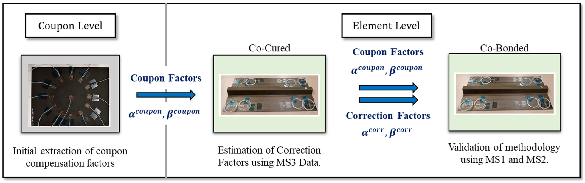
Illustration of the data passing route in the monostringer example.
Using the signals collected for MS3, the optimum compensation factors
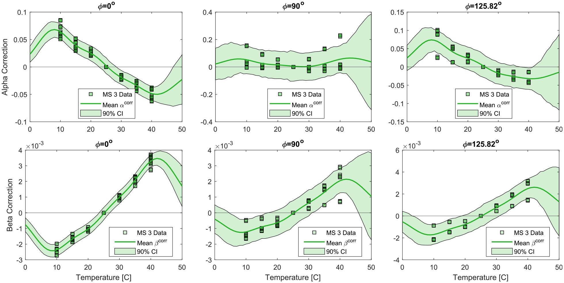
Fitted regression model for the correction factors
The use of the RBF in the Bayesian regression model allows to capture nonlinearities in the response of the correction factors
For comparison, the optimum compensation factors are also computed for specimens MS1 and MS2. The results are reported in Figure 8. In the same figure, the coupon (dashed line) and the corrected compensation factors after observing the measurements from MS3 (solid line) are also reported. It is illustrated that after observing the measurements from MS3, the corrected compensation factors are closer to the optimum values computed using equation (7) for MS1 and MS2, compared to using the compensation factors from the coupon scale directly.
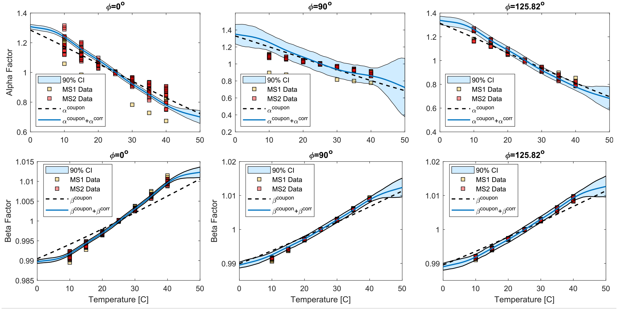
Comparison of compensation factors for different monostringer data.
Despite MS3 being Co-Cured, refining the compensation factors for specimens with similar geometry can improve the temperature compensation algorithm and help further mitigate the influence of temperature difference. The Bayesian regression model adopted here allows to continue the updating the correction factors after observing the MS3 data. For instance, the correction factors estimated from MS3 could be updated with the observations from MS1 before being applied to MS2.
The temperature difference between the baseline signal and the current leads to the computation of a non-zero damage index that could potentially mask the existence of damage in the structure. In Figure 9, the damage indexes for two signals of MS1 with temperature difference
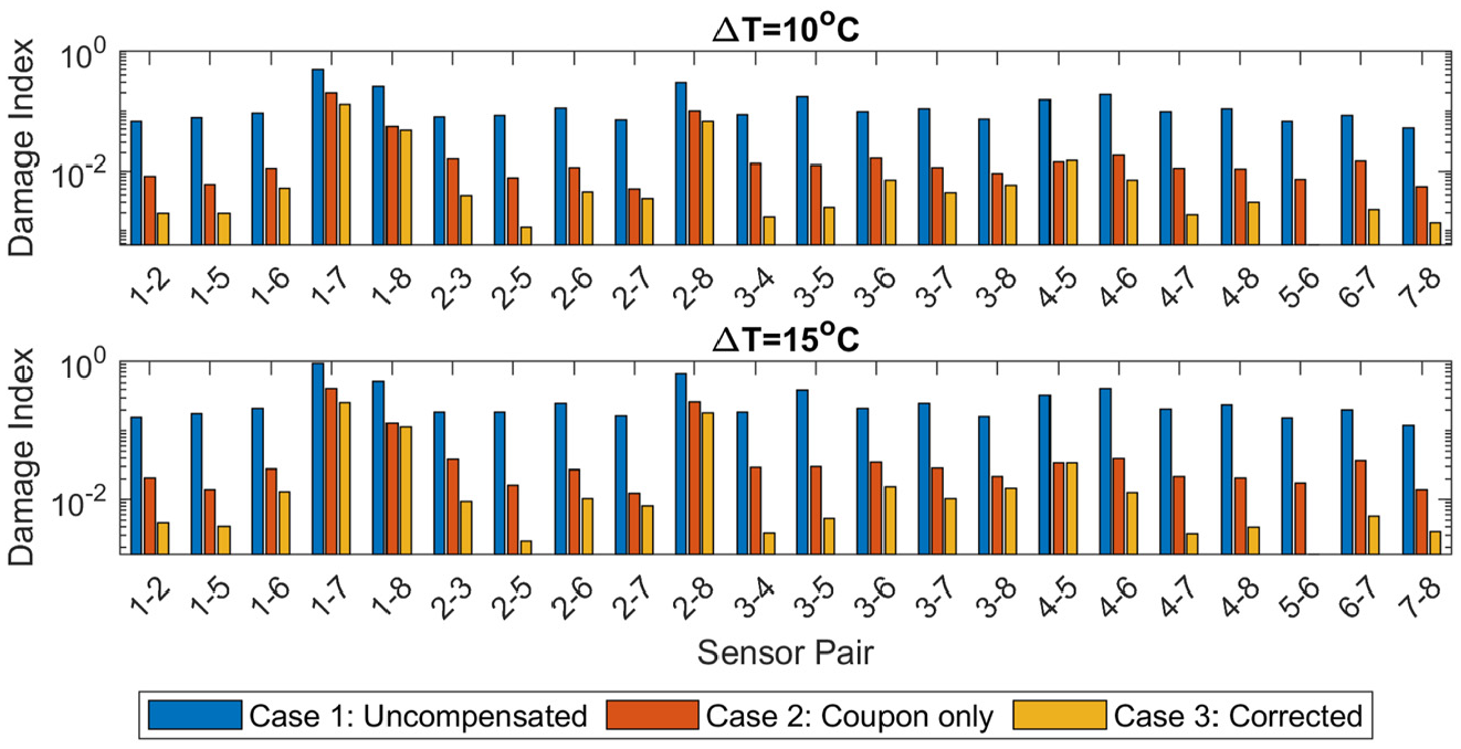
Comparison of the computed damage indexes from pristine signals collected from MS1 when
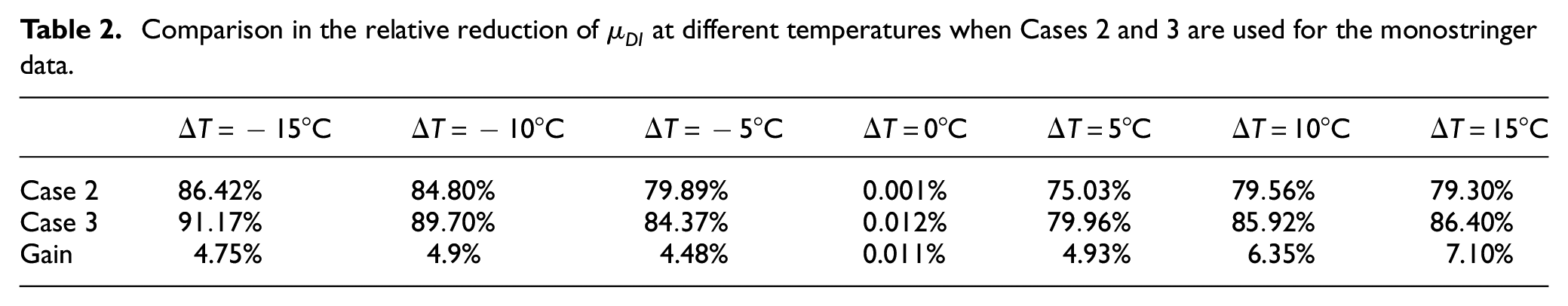
The value of
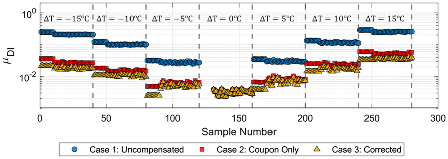
Comparison of the different compensation approaches for the available monitoring history. The y-axis is plotted in logarithmic scale.
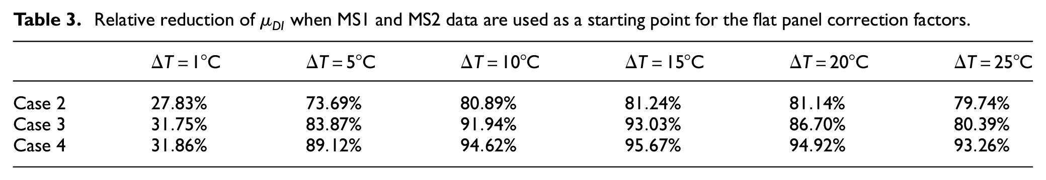
Comparison in the relative reduction of
Flat panel scale
In the previous section, the proposed temperature compensation was tested for specimens that belong to the same scale to validate the introduction of the correction factors. In this section, the proposed methodology is applied to the measurements taken from FP3 to demonstrate a case where the correction factors computed at a lower scale are transferred to the higher scales.
Cases 1 and 2 are the same as described in the previous example, corresponding to the no compensation and coupon compensation only. In Case 3, the correction factors are computed at the monostringer scale. Because the flat panels are also Co-Bonded, measurements taken from MS1 and MS2 are used for the estimation of the correction factors. Lastly, in Case 4, updating of the correction factors is allowed (see Figure 11). Let
Propagation of the temperature compensation factors from the coupon to the sub-component level.
Such situation can arise in practice in the case of large structures. It can be impractical to collect data at wide range of temperatures in the higher scales. Thus, using information from the lower scales provide a starting point for the estimations. Then, as new data become available during the operation of the structure, the estimations are updated. Each time new observations are available, the posteriors become the new priors and the Bayesian inference is repeated. In this example,
The measurements from FP3 with temperature range
The updating process of
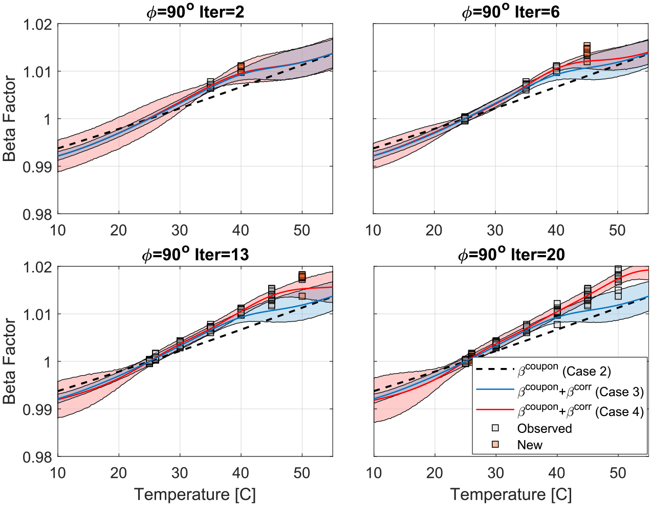
Illustration for the dynamic updating of
The computed
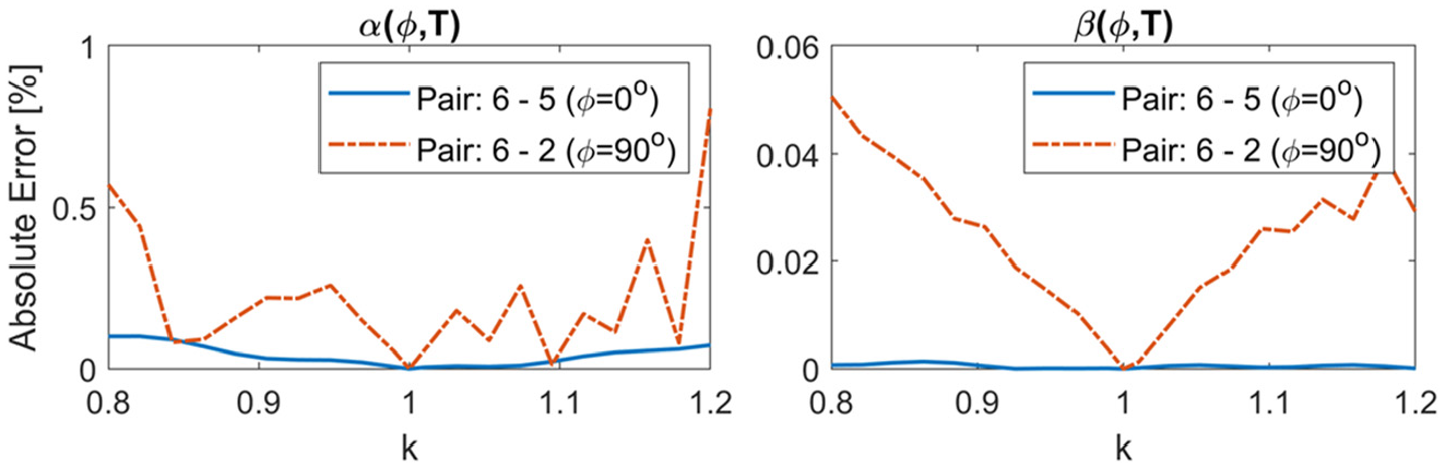
Comparison of the estimated
Case 4 indicates outliers that are influenced by the arrival sequence of the signals. These outliers indicate initially a similar response to Case 3. This is expected as Case 3 was used as starting prior for the correction factors. As the regression model gets updated, the performance of the compensation scheme improves. Take
Relative reduction of
The updating process could entail the risk of rendering the system insensitive to damage progression. In this scenario, a composite structure with only four bays has been considered. The value of the proposed framework however lies in its applicability to large-scale structures. The existence of damage will only affect the sensor readings in its immediate vicinity. Furthermore, measurements from similar aircraft in the fleet would also contribute to the database. It is therefore expected that the cases where undetected damage is included in the updating process will contribute only to a small fraction of the available data. Modifications in the regression method implemented could be explored to improve robustness to outliers. 45
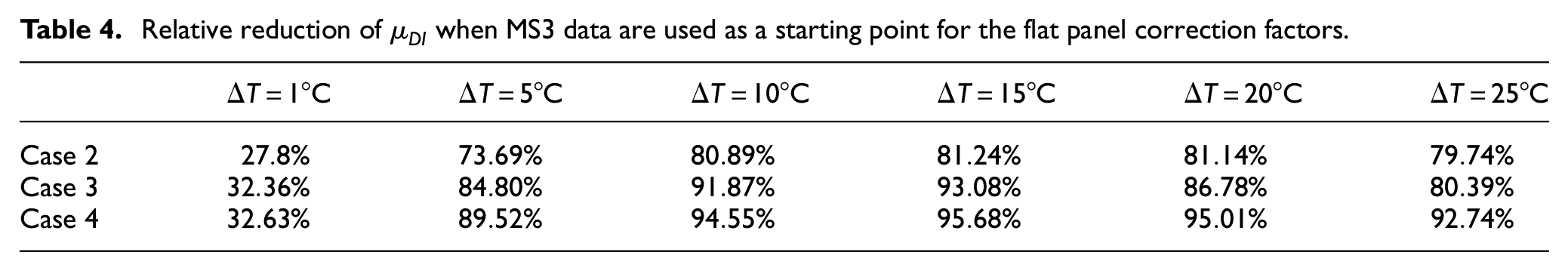
As a final example, the analysis is repeated with the difference that instead of having measurements available from specimens MS1 and MS2, only measurements from specimen MS3 are available. This is the worst-case scenario where the available measurements from the lower scales belong to a specimen with a different bonding process compared to the target structure (flat panel). The resulting reduction in
Relative reduction of
Damage detectability and localization results
Damage detection
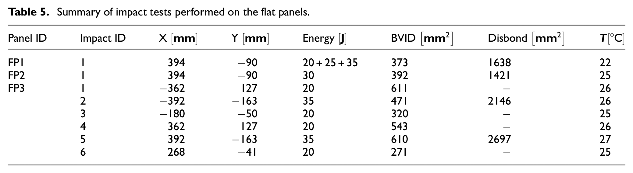
The motivation for the development of an accurate and robust temperature compensation algorithm is driven by the requirement for improved damage detection capabilities. To evaluate damage detectability when the proposed framework is employed, measurements are collected from the flat panels after a series of impacts. In total, eight impact events are carried out with energies between
Summary of impact tests performed on the flat panels.
For the damage detection, it is first required to construct the reference pristine vector
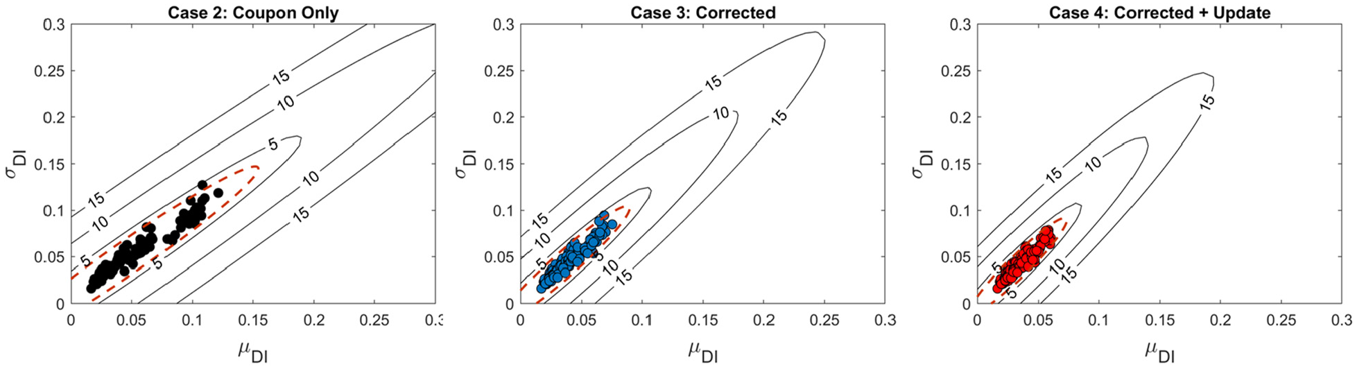
Illustration of the threshold limit when the temperature difference is up to
Distinction between a pristine and a damaged signal is done by setting up a threshold value,
In Figure 15, the damage vector
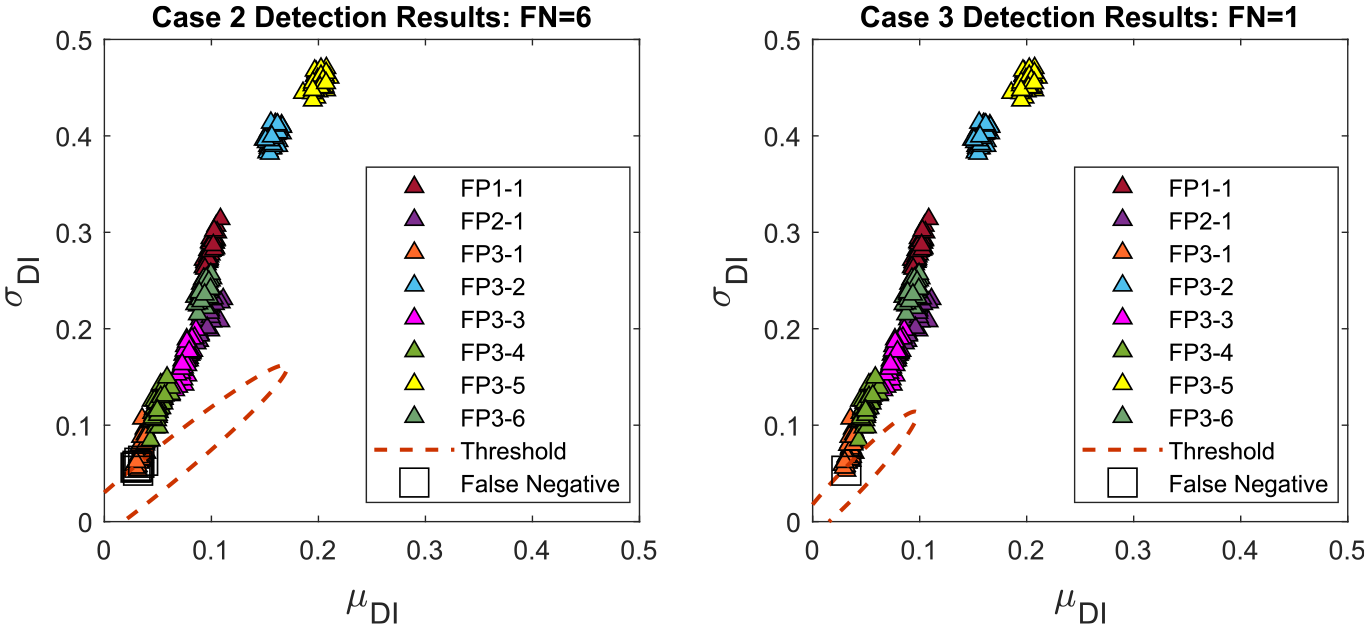
Illustration of damage vector
Apart from impact 1 of FP3, all other events are correctly identified, irrespective of the compensation method implemented. For impact 1 of FP3, when Case 2 is used, the detection methodology produced six False Negative (FN) indications. Transitioning to Case 3, the uncertainty in the temperature compensation is decreased and the number of false positive indications are reduced to 1 (see also Figure 15). A single false negative is also reported when case 4 is implemented for the temperature compensation.
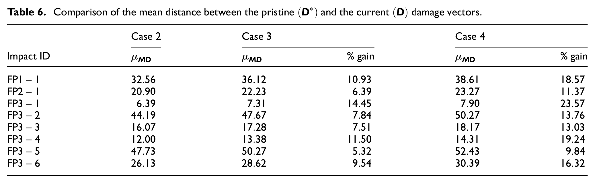
Since the uncertainty in the pristine data is reduced, the threshold distance defines a smaller region where pristine data are expected (see red dashed line in Figures 14 and 15). As such, when the temperature compensation scheme is improved, the Mahalanobis distance between
Comparison of the mean distance between the pristine
Damage localization
The impact sequence FP3-1 to FP3-6 is used to study damage localization with multiple impact events and highlight the complexity of the scenario assumed. To also consider the effect of temperature difference, the baseline signal temperature is selected as
Localization imaging results for a sequence of impacts with
To evaluate the localization for each compensation method, the accuracy and the precision of the estimated locations are computed following BS ISO 5725-1.47,33 Let
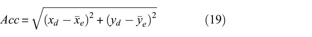
The precision of the location estimate can be quantified based on the area of the 95% error ellipse. Let

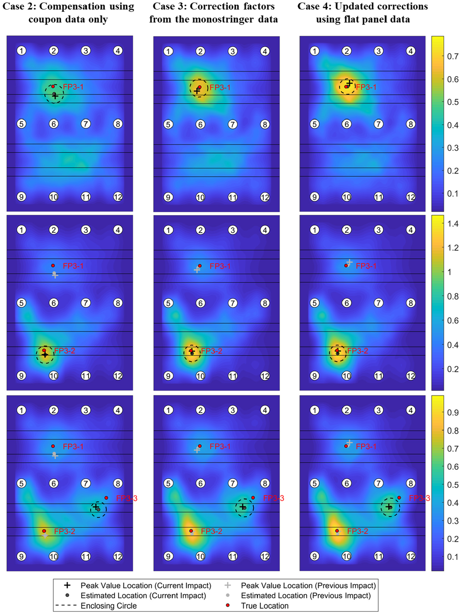
Simply picking the highest value of the localization algorithm may lead to erroneous readings due to signal noise. To reduce this effect, the location estimate presented in Ref [33] is adopted. The grid points whose values are above the 1% quantile are selected as possible damage location. Then, a circle is constructed that encloses the selected points. The damage location is to be at the center of the constructed circle. Effectively, this location estimate finds the center of the region with the highest localization values. For subsequent impact events, the values of the imaging algorithm are subtracted to estimate the location of the latest event. In Figure 16, the estimated location for each impact event is indicated with a black circle.
In Figure 17, the mean estimated damage locations are indicated for each impact event along with the 95% error ellipses Additionally, the accuracy and the precision computed for the localization of each impact event is reported in Table 7. As expected, impact events FP3-1 and FP3-4, that demonstrate the lowest damage indexes (see also Figure 15), have the lowest localization precision. The lowest accuracy is obtained for impact FP3-3 where the localization algorithm indicates that the impact was located below the stringer foot. Furthermore, the peak value of the imaging methodology is compared for each of the cases. Higher peak values are less likely to be confused with external signal degradation mechanisms (e.g., noise). The peak value is defined as the maximum value of the imaging algorithm within the enclosing circle constructed for the estimation of the damage location of each impact event. The location of each peak is indicated with a black cross in Figure 16 while the peak values are reported in Table 7.
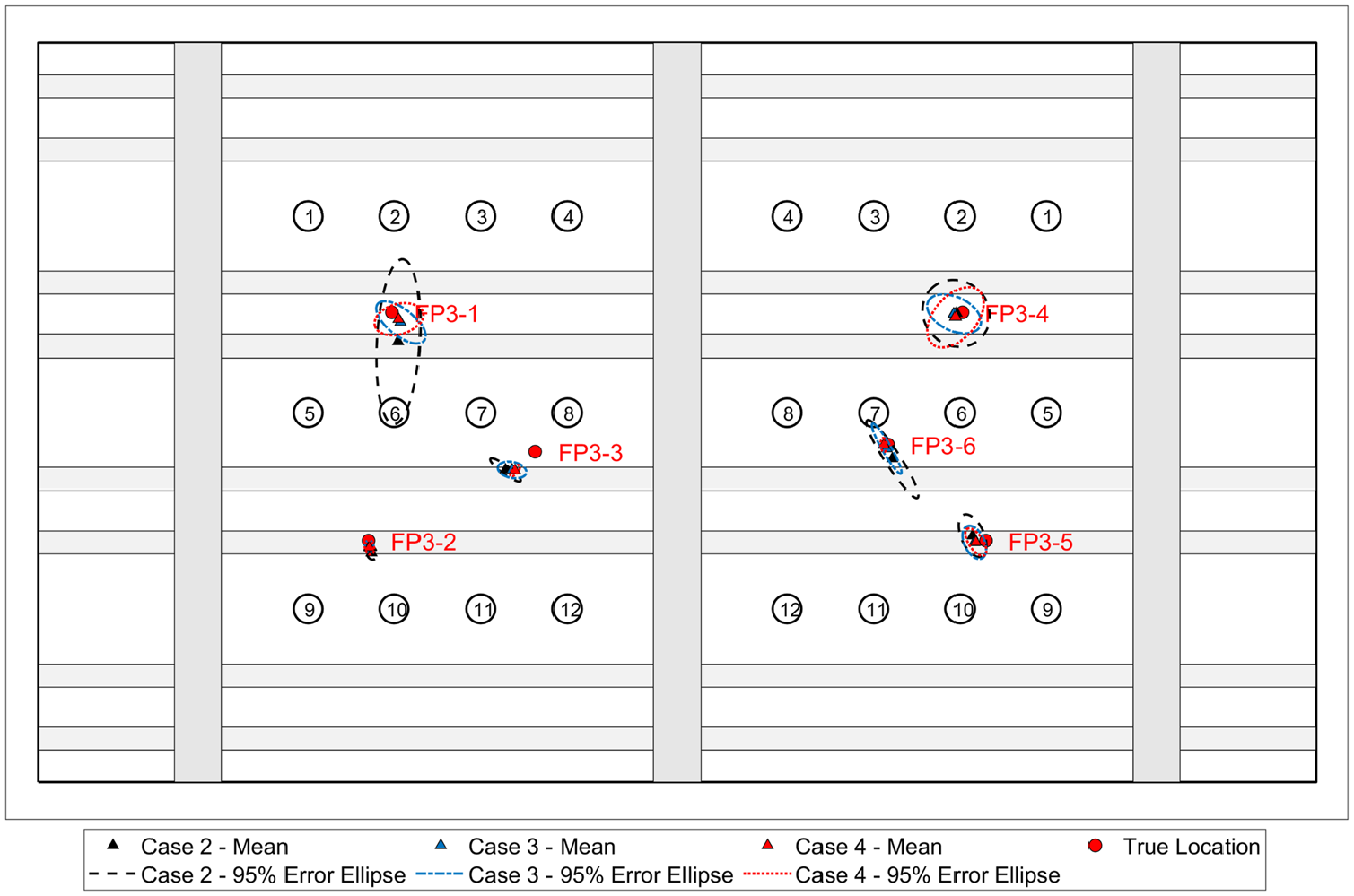
Damage localization results for all impact events on FP3 with
Summary of the computed accuracy and precision for each impact event.
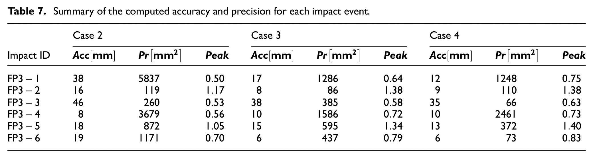
Compared to Case 2, Cases 3 and 4 and can lead to improved damage localization. Use of the monostringer data for the compensation of the flat panel signals (Case 3) leads to an average improvement of 29% for the accuracy and 34.74% for the precision. This improvement can be further increased when the correction factors at the flat panel scale are allowed to be updated (Case 4) up to 32.5% for the accuracy and 57.5% for the precision. Cases 3 and 4 increase the peak value near the impact location by 20.7% and 27.9%, respectively, improving the reliability of the localization methodology. The results demonstrate the possible improvement in the accuracy and the precision of the damage localization algorithm.
Conclusions
Common temperature compensation approaches require the collection of large datasets that might be infeasible for large and complex structures. To alleviate this restriction, an up-scaling framework was proposed that leverages observations made at lower scale to improve the temperature compensation at the higher ones. The structural complexity of each scale was considered through the introduction of additional correction factors and a Bayesian regression model was used to estimate their values at different inputs and propagate the information collected between the scales.
First, the performance of the correction factors was demonstrated for measurements taken from monostringer specimens. Although the bonding process was not the same across all monostringers, the estimated correction factors were able to improve the temperature compensation compared to using the coupon compensation factors directly. Then, the correction factors were taken to a higher scale and were applied to the flat panel measurements. The proposed method was able to achieve a 7.19% reduction in the residual signals. Furthermore, through the Bayesian updating of the correction factors, the reduction can be increased up to 12.49%. Similar results were obtained when the data from the Co-Cured monostringer are used for the compensation of the Co-Bonded flat panels.
Significant improvement is also reported regarding the detection and localization of damage. Since the accuracy of the compensation is increased, the uncertainty in the definition of the threshold is reduced. On average, during damage detection, the Mahalanobis distance for the damaged cases presented was increased by 9.18% and 15.71% for Cases 3 and 4, respectively. During damage localization, the amplitude and time of arrival of the damage scattered signal was captured more accurately, improving the accuracy and the precision of the localization estimate. Case 3 improved the accuracy by 29% and the precision by 34.74% while Case 4 offers improvement up to 32.5% for the accuracy and 57.5% for the precision. Moreover, when the proposed framework is implemented, the imaging algorithm led to higher amplitude estimates (on average 20.74% and 27.85% for Cases 3 and 4, respectively) at the damage locations, increasing the reliability of the damage localization.
Although the scenario adopted in this study assumes only three scales (coupon-monostringer-flat panel), the framework can be applied to multiple distinct scales till the final structure. The specimens used in this study had similar features and sensor networks arrangements. Multiple paths within the same framework could also be created to account for a variety of structural features (such as curvature and change of thickness.) that might appear in a complete aircraft. The effect of temperature variation can be studied for such cases using smaller specimens at lower levels and a library of dedicated compensation and correction factors can be created for each one. A comparison between the different temperature compensation methodologies that have been proposed in the literature would be a potential research area for future investigations. Such comparison would not only illustrate the performance of each method but also highlight the requirements, benefits, and limitations of each method if up-scaling is attempted.
Footnotes
Appendix 1
In this Appendix, the imaging algorithm adopted for the localization of a damage event is described briefly. Damage localization can provide information regarding the existence of damage near critical areas and help the maintenance crew to focus subsequent Non-Destructive Testing (NDT) activities at specific areas, reducing the manual labor required. Various damage detection algorithms have been proposed in the literature. 48 In this study, localization is carried out by combining two approaches, the delay-and-sum (DAS) 49 and the reconstruction algorithm for the probabilistic inspection of defects (RAPID). 17 The former algorithm aims at associating the damage scattered signals with a specific location of the structure based on its time of arrival and the wave propagation velocity. The later, projects the damage index computed between a sensor pair on its path and the location of the damage can be inferred when multiple paths that cross the same location demonstrate high damage indexes.
Implementing the DAS algorithm, the following imaging field can be obtained as
where
Next, an imaging field is obtained using the RAPID algorithm as
where
The RAPID algorithm can provide reliable localization results at the intersection of sensor pairs limiting the spatial resolution of the imaging technique. The DAS algorithm on the other hand is influenced by boundary reflections and wave attenuation at later time instants that can reduce its temporal resolution. To improve the imaging results, the two fields are combined at each pixel location using
For more information on the localization approach, the interested reader is referred to Ref [9]and the references therein.
Declaration of conflicting interests
The author(s) declared no potential conflicts of interest with respect to the research, authorship, and/or publication of this article.
Funding
The author(s) disclosed receipt of the following financial support for the research, authorship, and/or publication of this article: The research leading to these results has gratefully received funding from the European JTICleanSky2 program under the Grant Agreement n° 314768 (SHERLOC). This project is coordinated by Imperial College London and lead by Leonardo S.p.A. as Topic Manager.