
Abstract
The tiltrotor design is favored for urban air mobility (UAM) prototypes due to the combination of vertical takeoff and landing (VTOL) capability and efficient forward flight. With rising UAM air traffic at low altitudes, noise from these aircraft is a crucial design factor. Most tiltrotor noise research focuses on high disk loading and Reynolds number setups, leaving smaller aircraft configurations less explored. This study investigates aero-acoustic trends from rotor-wing interaction at low disk loading (
Keywords
Introduction
In the near future, urban air mobility (UAM) will revolutionize intra-city transportation. 1 The Federal Aviation Administration (FAA) defines a UAM vehicle as a highly automated aircraft that is used to transport passengers or cargo at lower altitudes within urban and suburban areas. The potential increase in urban air traffic can cause many issues, though, including noise pollution. The FAA and European Union Aviation Safety Agency (EASA) may implement strict noise limits in the coming years and meeting these new noise limits requires deeper insights into aero-acoustics in UAM technologies. Vertical take-off and landing (VTOL) capability is of great importance in UAM technologies since runways are not available or practical in urban areas. VTOL vehicles include but are not limited to helicopters, multirotor copters, tiltwings, tiltrotors, tailsitters, and multirotor planes (quadplanes or hybrid planes). 2 Tiltrotors have gained popularity because they combine VTOL capability with more efficient fixed-wing forward flight. Depending on rotor placement, the rotor wake in hover could impinge on various parts of tiltrotors including the wing, fuselage, empennage, or support frame.
The use of rotors for VTOL vehicles in UAM technologies raises a bigger concern of noise.
1
Aerodynamics and aero-acoustics of propellers and rotors have been under investigation for decades.3,4 Examples of previous aero-acoustic research have focused on a single isolated rotor (without a wing underneath),1,5–9 two or multiple tandem rotors (without a wing underneath),10–13 and scaled tiltrotor models (with a wing underneath): V-22
14
and XV-15.15–17 The aforementioned aeroacoustic studies on the V-22 (Figure 1(a)) and XV-15 (Figure 1(b)) are examples of high disk loading and high Reynolds number (Re) cases. Zawodny and Boyd
18
performed a rotor-airframe aero-acoustic interaction study at low disk loading and Re, close to the order of magnitude in our case (refer to Table 1). While rotor-airframe interaction is not part of this investigation, their work provides some guidance on how to design the experiments in this study. In their work, the vertical proximity between the rotor and the airframe was varied and the acoustic data was acquired at different heights above the ground. Two types of airframes—a generic airframe simulated by a straight tube and a conical airframe—were investigated. The parameters for the tiltrotors studied in aero-acoustics. afrom a single isolated rotor; bat the 75% radius of the blade.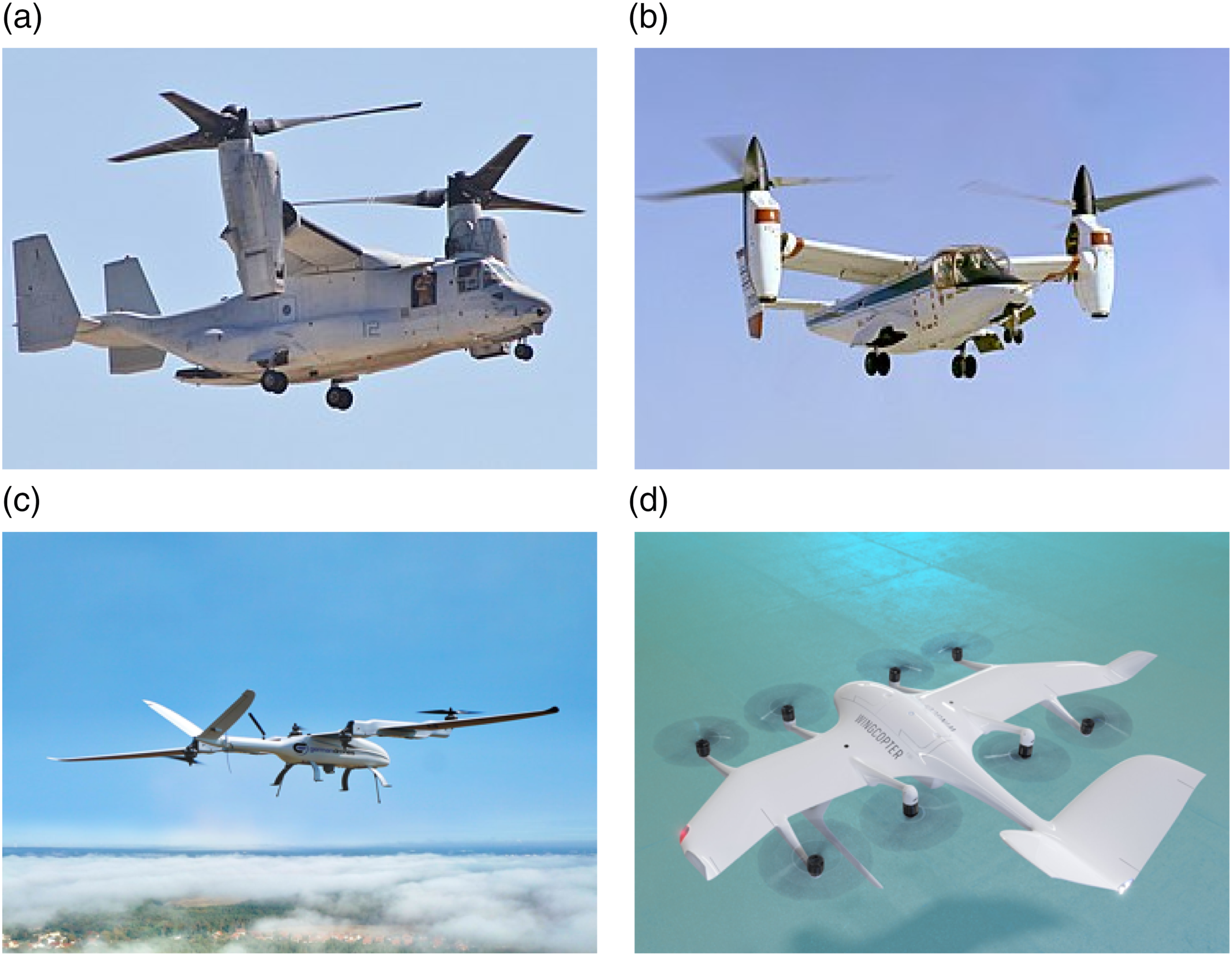
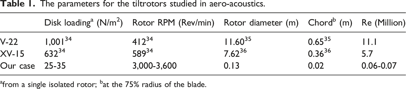
In tiltrotors designed for UAM, the rotor diameter is reduced compared to the wing chord and multiple rotors are employed. Germandrones Songbird (Figure 1(c)) and Wingcopter (Figure 1(d)) are two examples of commercial UAM tiltrotors at the small-UAV scale (typically 15 cm to 2 m 19 ). Thus, the results obtained from the V-22 and XV-15 (refer to Table 1) may not be applicable to small UAM tiltrotors. Marte and Kurtz 3 listed six major design requirements of which two are low disk loading and minimum interference with rotor flow for rotor noise alleviation. Table 1 compares the disk loading and Re between our case and the V-22 and XV-15 studies. The disk loading and Re in our case are considerably smaller—about one to two orders of magnitude—when compared to full-scale counterparts.
In this study, the aero-acoustic effects of rotor wake impingement on a wing at low disk loading and Re are evaluated. A single two-blade rotor is adopted and positioned at varying heights relative to the wing. Two types of wings—a flat plate and a NACA 0012 airfoil—are used. The ratio of rotor diameter to wing chord is one, which is comparable to small-UAV and distributed rotor designs in UAM. In addition to rotor height, the effects of rotor RPM and rotation direction on the aero-acoustics are quantified. To assess the accuracy of the test apparatus, the effects of possible flow circulation in the anechoic chamber and isolated rotor noise are checked. The aerodynamic performance of our case has been previously presented in Refs.2,19,20 and will be discussed in context with the aero-acoustic results. With a more comprehensive understanding of rotor-wing interaction on the aero-acoustics at low disk loading and Re, better insights and design strategies regarding rotor arrangement and noise abatement in small UAM tiltrotor designs can be formed.
Experimental approach
Test apparatus
To study the aero-acoustics in a single-rotor/wing interaction configuration, a test setup with one rotor and a wing was designed and built (Figure 2(a)). The aero-acoustics experiments were conducted in the anechoic chamber at North Carolina State University of which the dimensions are 5.2 m × 5.2 m × 5.3 m (depth × width × height). The low-frequency cutoff of the anechoic chamber is approximately 80 Hz and the chamber was designed following ISO 3745.
7
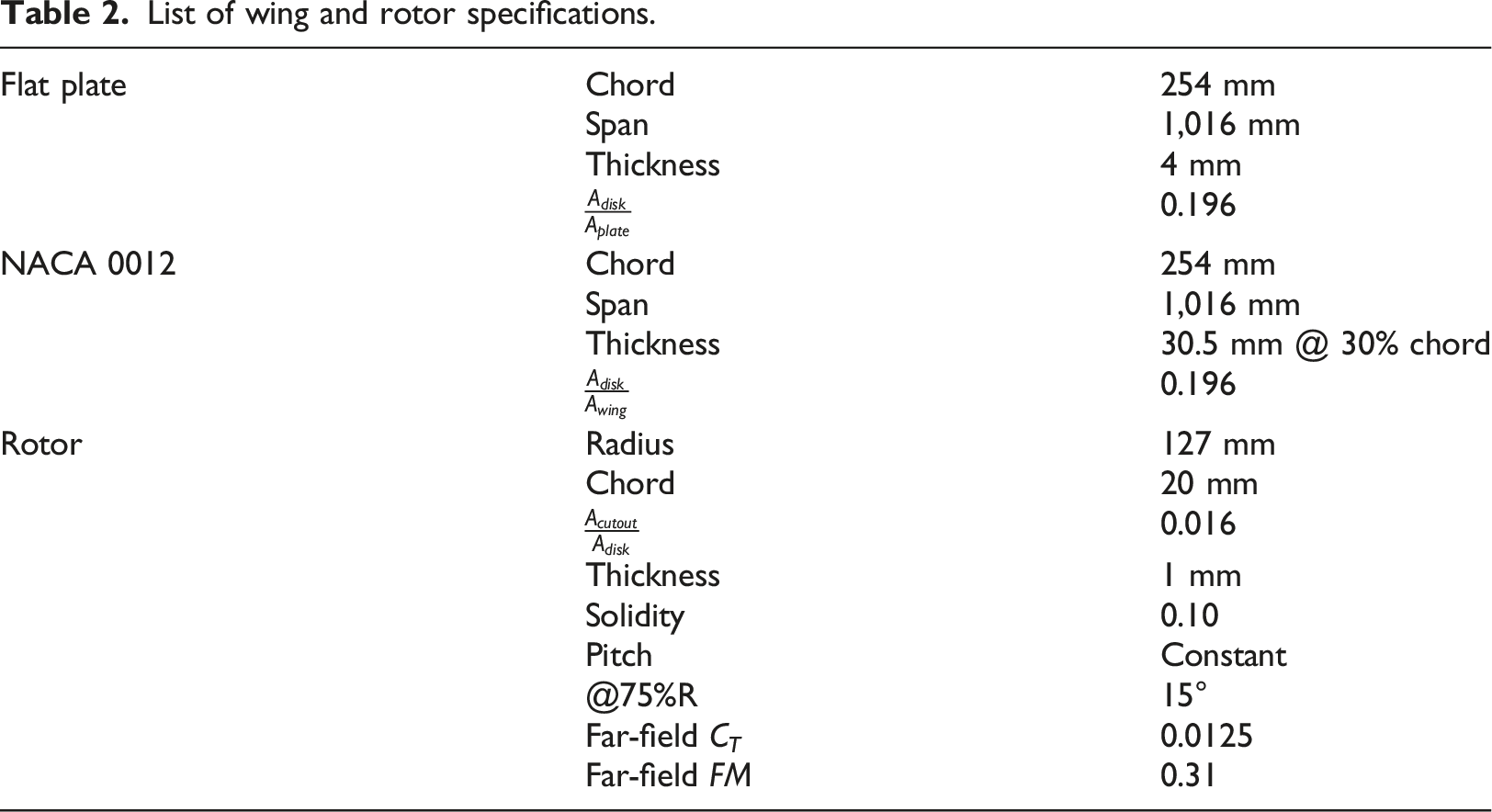
The chamber floor is grated and wedge-shaped absorbers are placed under the floor. Rotor height, h, is set by sliding the cantilever rail along the vertical rail as shown in Figure 2(b). The rotor center was aligned to the wing center. To minimize the ground effect, the wing was placed at a height of 7.6 R above the chamber floor. The constant-pitch propeller (15°)19,21 and two wings—a flat plate simulating a generic wing and a NACA 0012 wing—were selected. The selection of the constant-pitch propeller is to simplify the blade geometry and assist in future computational simulation. Table 2 lists the specifications of the wings and the rotor, where C
T
and FM are rotor thrust coefficient and figure of merit, respectively. The NACA 0012 wing was fabricated by additive manufacturing and has a maximum surface roughness height between 113.6 and 170.1 μm.22,23 Experimental setup of acoustic measurements in single-rotor/wing interaction. (a) a picture, (b) front view and (c) top view. List of wing and rotor specifications.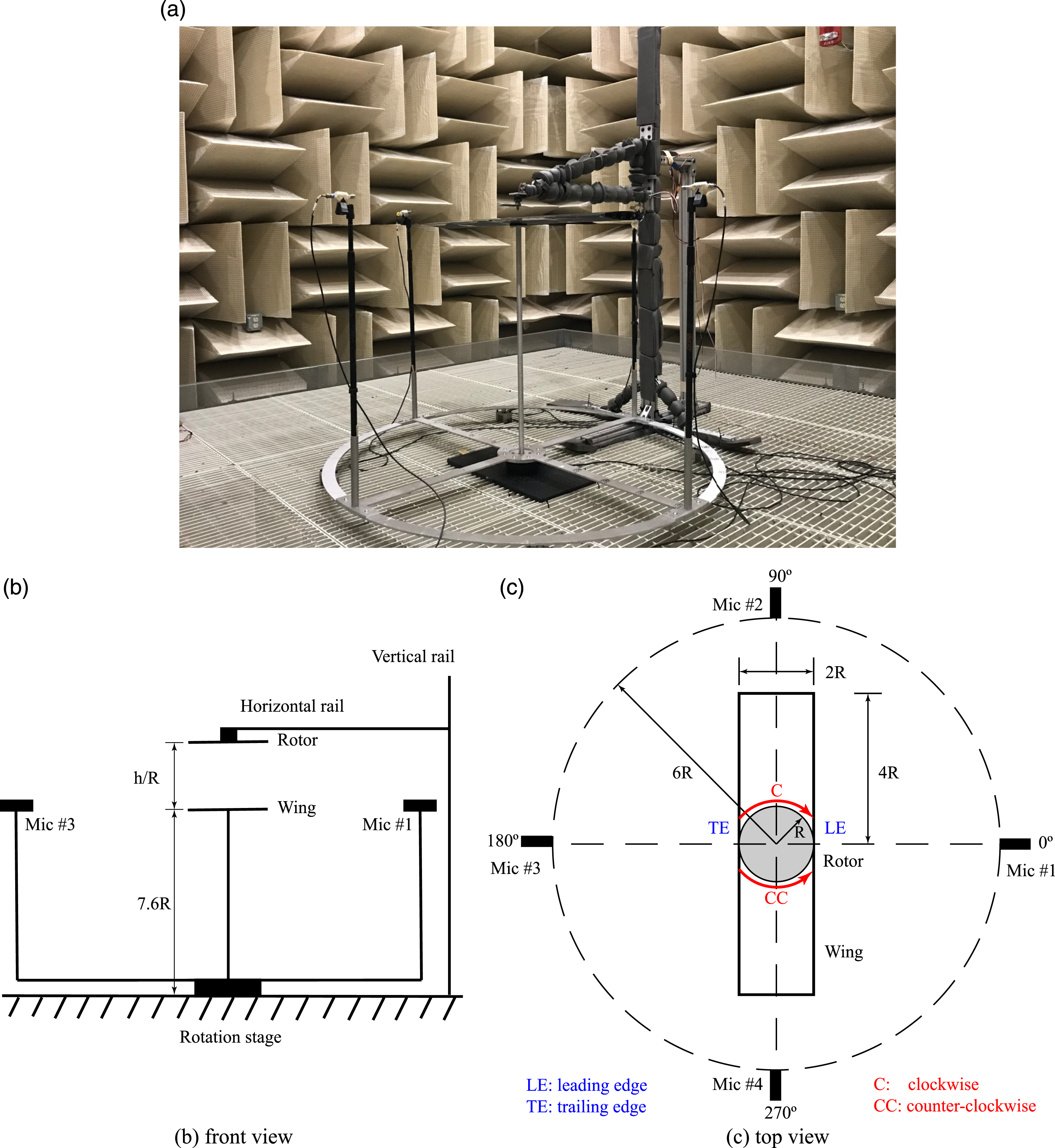
To acquire the far-field acoustics measurements, four Bruel & Kjaer Type 4188-A-021 microphones were used. The microphones were set apart from the rotor center at a distance of 6R as recommended in Barry et al 5 for far-field noise and spaced at an angle of 90° (refer to Figure 2(c)). To check the directivity of the far-field acoustics, an HDR50 rotation stage from Thorlabs was used to rotate the microphones at every 15°. The positioning accuracy of the rotation stage is 0.1°. Two blade rotations (C and CC, as shown in Figure 2(c)) and one microphone height (wing plane) were investigated.
Data acquisition system
Acoustic data was acquired using four Bruel & Kjaer Type 4188-A-021 microphones with sensitivities of 29.01, 33.19, 33.42, and 33.08 mV/Pa and an HDR50 rotation stage controlled by a BSC201 stepper-motor controller through custom LabVIEW software. A National Instruments NI-9234 sound and vibration module was used for signal conditioning and data collection. The sound and vibration module was housed in an NI cDAQ-9174 and was connected to a PC using a USB cable. The rotor was driven by a Multistar ELITE 2810 KV750 motor via a RC Electric Parts 30A electronic speed controller powered by an 11.1 V lithium battery. A powered hall-effect sensor (A3144) was used to track a small neodymium magnet placed on the motor shaft and measure the rotor RPM. The signal was acquired with an NI USB-6008 DAQ recorder. To adjust the rotation speed, a potentiometer was used to set the pulse width modulation output from an Arduino Uno controller to the electronic speed controller.
Test procedure
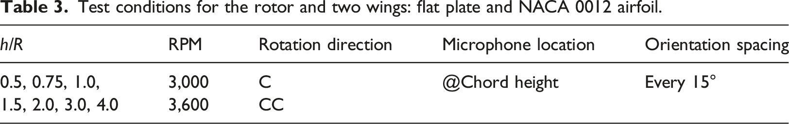
Test conditions for the rotor and two wings: flat plate and NACA 0012 airfoil.
Data processing
Welch’s method utilizes the Fast Fourier Transform (FFT) algorithm to estimate power spectra. This involves dividing the data into segments, computing modified periodograms for each segment, and then averaging these modified periodograms to obtain the final power spectrum estimate.
24
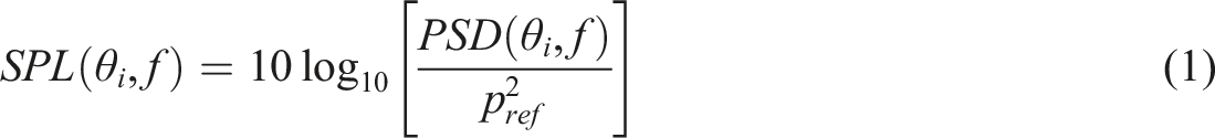
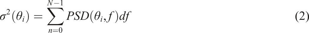
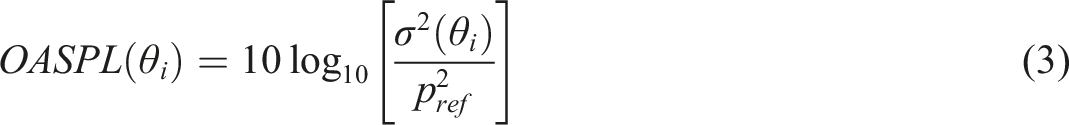
The pwelch built-in function in MATLAB (version 2021) was used to convert the acoustic measurements to power spectral density (PSD) estimates. The acoustic data was divided into segments with a maximum 12,000 samples. A Hamming window with 50% overlapping was selected. Once the PSD estimates were obtained from the pwelch function, the power spectra of sound pressure level (SPL) and the overall sound pressure level (OASPL) were calculated using equations (1)–(3). The specific application of these equations is elaborated upon in Maier et al.
7

Assessment of the test apparatus
In the initial subsection, we investigate the influence of flow recirculation within the anechoic chamber, a prevalent technique in rotor/propeller experiments that ensures the accuracy of the testing arrangement. The subsequent subsection clarifies the isolated rotor noise, establishing the baseline for this study. To enhance the clarity of result presentation and discussion, the aero-acoustic discoveries pertaining to the interaction between a single rotor and wing (outlined in the upcoming section) are contrasted with those in the second subsection.
Flow recirculation in the anechoic chamber
Recently, Stephenson et al
27
and Nardari et al
28
showed that the effect of flow recirculation in their anechoic chambers increased the noise of the isolated rotors at higher harmonic frequencies. In other words, the flow recirculation in the anechoic chamber is that the flow induced by the rotating rotor impinges on the chamber floor and recirculates back to the top of the rotor due to rotor operation in a confined environment for a certain period. To check whether flow recirculation in our anechoic chamber influences the acoustic spectrum of the tested rotor, similar to Gojon et al,
1
a spectrogram (the spectrogram built-in function in MATLAB 2021 was used) of 60 s for the two RPMs (3,000 and 3,600) at 90° (measured by microphone #2) is plotted in Figure 3. In the check tests, the rotor without a wing underneath was placed at h/R = 0.5, the closest case to the chamber floor in the aero-acoustics measurement experiments. When a wing is installed below the rotor, the rotor thrust follows an asymptotic and increasing trend of Acoustic spectrogram of the isolated rotor for RPM (a) 3,000 and (b) 3,600 at 90° in the wing plane.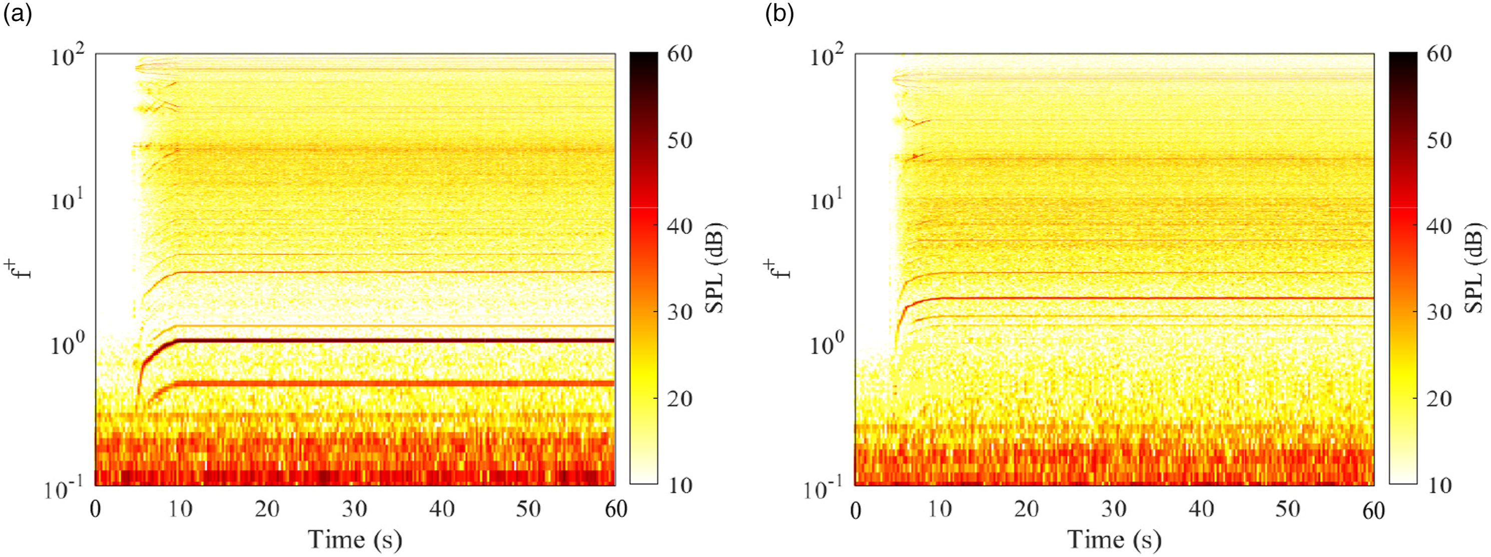
Isolated rotor noise
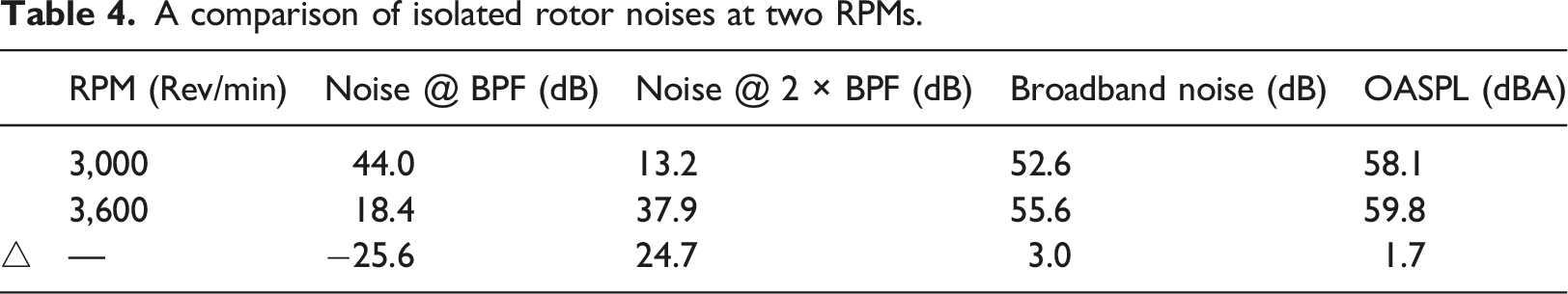
The SPL plots of the isolated rotor are depicted in Figure 4. Distinct tonal peaks emerge at f+ = 0.5 and f+ = 1 (the BPF) for RPM = 3,000, respectively. Upon the RPM rising to 3,600, these peaks at f+ = 0.5 and 1 dissipate, with noise at f+ = 2 assuming the role of the principal tonal noise, suggesting a possibly distinctive attribute of this constant-pitch propeller. A similar phenomenon was observed during testing of a wooden propeller (9 × 7) by the first author. Table 4 provides a breakdown of noise at the BPF and the first harmonic (2 × BPF), in addition to the broadband noise and OASPL. The calculation of broadband noise employs the findpeaks built-in function in MATLAB 2021 for peak detection. After the removal of detected peaks, the remaining SPL values are summed to determine the broadband noise. While Gojon et al
1
calculated broadband noise at higher frequencies, our investigation emphasizes the amplified broadband noise at low frequencies due to the deflected rotor wake during rotor-wing interaction (discussed in the subsequent section). As a result, the broadband noise calculation here encompasses the entire frequency range. Despite the RPM increase from 3,000 to 3,600 having an insignificant effect on OASPL, there is a 3 dB increase in broadband noise, as evident in Figure 4(b) (visible after f+ > 3). Notably, averaged values measured over one revolution are used in Table 4 for data comparison in the subsequent section between the isolated rotor and the rotor interacting with a wing. SPL comparison of the isolated rotor noise for RPM (a) 3,000 and (b) 3,600 at 90° in the wing plane. A comparison of isolated rotor noises at two RPMs.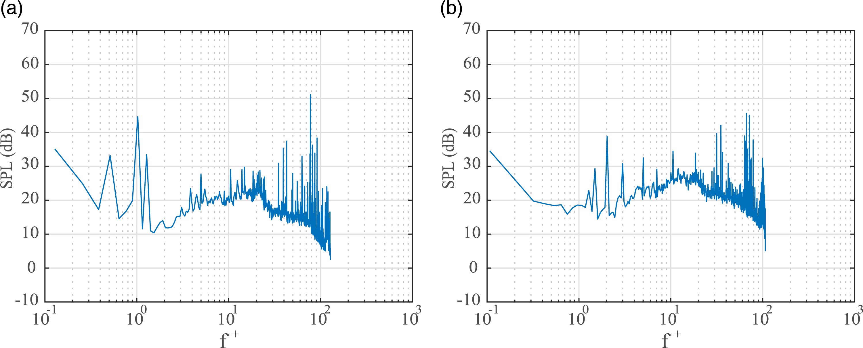
Aero-acoustics in single-rotor/wing interaction
Within this section, two distinct wings—a flat plate and a NACA 0012 airfoil—were positioned independently beneath the same rotor, diverging from the isolated rotor test configuration expounded in the previous section. This phenomenon encompasses rotor/wing interaction, wherein the rotor wake downstream is perturbed by the presence of the wing. This deflected rotor wake possesses the potential to reshape the noise distribution. In the subsequent segments, we systematically assess and present the ramifications of rotor height, rotation direction, and RPM on aero-acoustics within the context of single-rotor/wing interaction.
Influence of rotor height
We commence by investigating the influence of rotor height on the aero-acoustics within this study. Figure 5 presents a comparison of the four acoustic parameters discussed in the preceding subsection for both a flat plate and a NACA 0012 wing, set at RPM 3,000 and rotating in a clockwise (C) direction, across seven values of h/R. For context, the values from the isolated rotor (depicted by dashed black lines) in the first row of Table 4 are also incorporated. The noise signatures of both wings, across all rotor heights, display asymmetry along the chordwise centerline (0° - 180°) due to rotation direction, despite the geometrically symmetrical measurement setup in this orientation. Moreover, the noise levels for the 1st harmonics, broadband noise, and OASPL consistently surpass or equal those of the isolated rotor. Particularly notable is the occurrence of maximum increases in the three noise parameters at 90° and 270° directions. Considering the impact of rotor height on these three parameters in rotor-wing interaction, the 30° and 210° directions undergo the most substantial increase in the absence of wing curvature (flat plate scenario) as the rotor descends from h/R = 4 to 0.5. In the presence of wing curvature (NACA 0012 case), the effect of rotor height in the 30° direction diminishes, and the acoustic spectrum is less susceptible to rotor height variations in the right half circle (270° - 90°) due to increased curvature at the leading edge. For both wings, the impact of rotor height is least pronounced at 0°, 90°, 180°, and 270°, except for the h/R = 0.5 scenario with the flat plate. The noise spectrum between (a) the flat plate and (b) the NACA 0012 wing for RPM 3,000 and in clockwise (c) direction.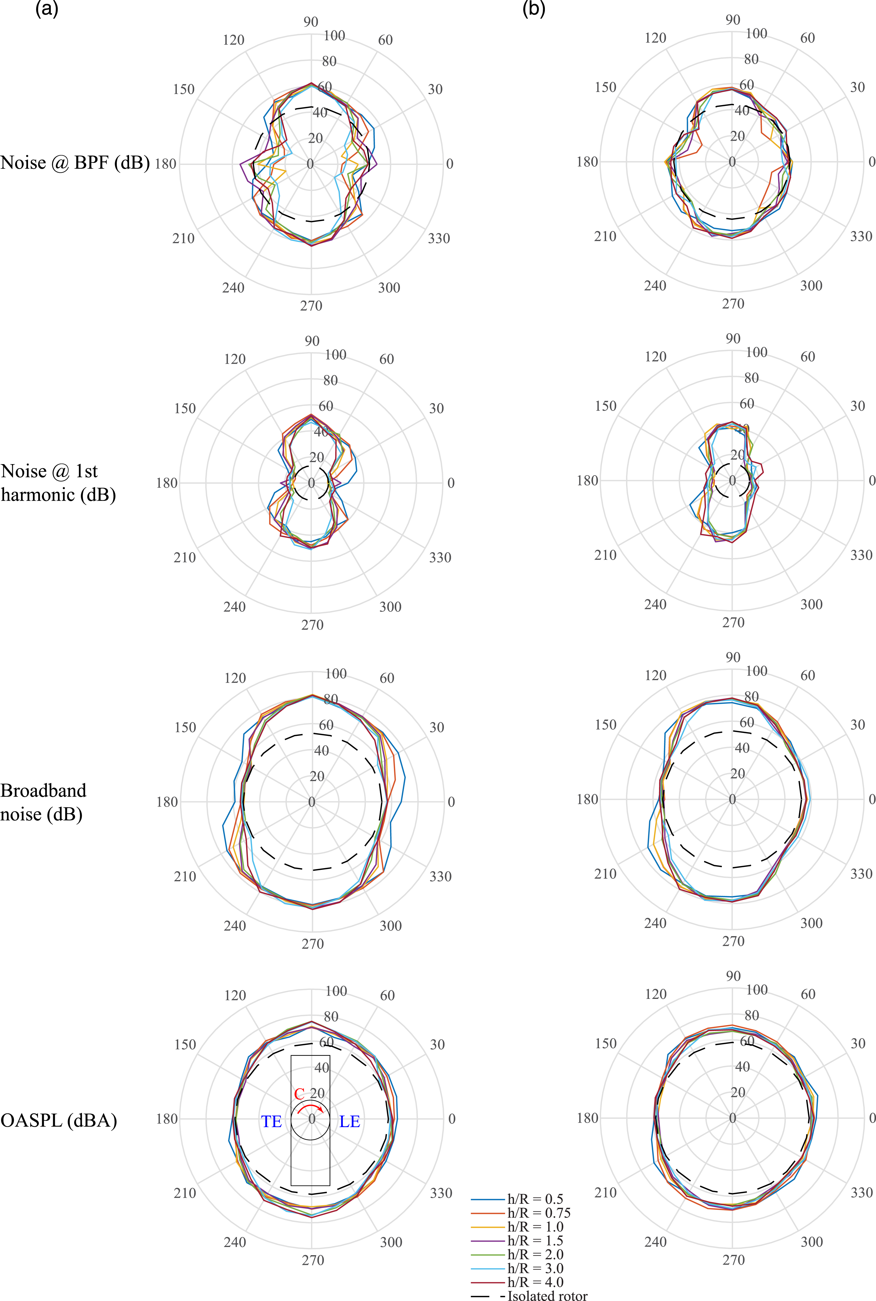
However, the impact of the deflected rotor wake on the noise level at BPF can either augment or diminish, contingent on direction. At 90° and 270° directions, both wings exhibit minimal fluctuations, akin to the other three counterparts. Conversely, noticeable alterations manifest for the flat plate at 0° and 180° directions in contrast to the NACA 0012 wing. To gain deeper insights into this phenomenon, SPL plots at 0° and 90° directions are selected for a comparative analysis, as shown in Figure 6. This comparison encompasses four h/R scenarios in addition to the isolated rotor condition. At 0° direction, the noise spectrum closely resembles that of the isolated rotor, especially for the NACA 0012 wing. To be noticed, the main tonal peaks exhibit an ascending trend as h/R diminishes for the NACA 0012 wing, indicative of a shift in loading noise. In contrast, for the flat plate, the deflected rotor wake reaches the microphone at h/R = 0.5, leading to the elimination of the principal tonal peak and an upsurge in broadband noise at low frequencies (f+ ≤ 3). Upon transitioning to the 90° direction, the SPL plots closely resemble those of the h/R = 0.5 case at 0° direction, albeit with differing magnitudes. Additionally, the broadband noise diminishes at higher frequencies (f+ ≥ 5) for both wings in this direction, particularly pronounced for the flat plate, as h/R decreases. The insights garnered from Figure 6 elucidate the nearly consistent trends induced by rotor height on the four parameters at these two distinct directions: 0° and 90°. For alternative directions, the effect of the deflected rotor wake may lead to a reduction rather than an elimination of the BPF peak, contingent on the strength of the deflected rotor wake reaching the microphones. Consequently, variations in the noise at BPF (the primary tonal noise at RPM 3,000) exhibit the most significant fluctuations at varying rotor heights. SPL comparison between (a) the flat plate and (b) the NACA 0012 wing for RPM 3,000 and in clockwise (c) direction at 0° and 90° direction.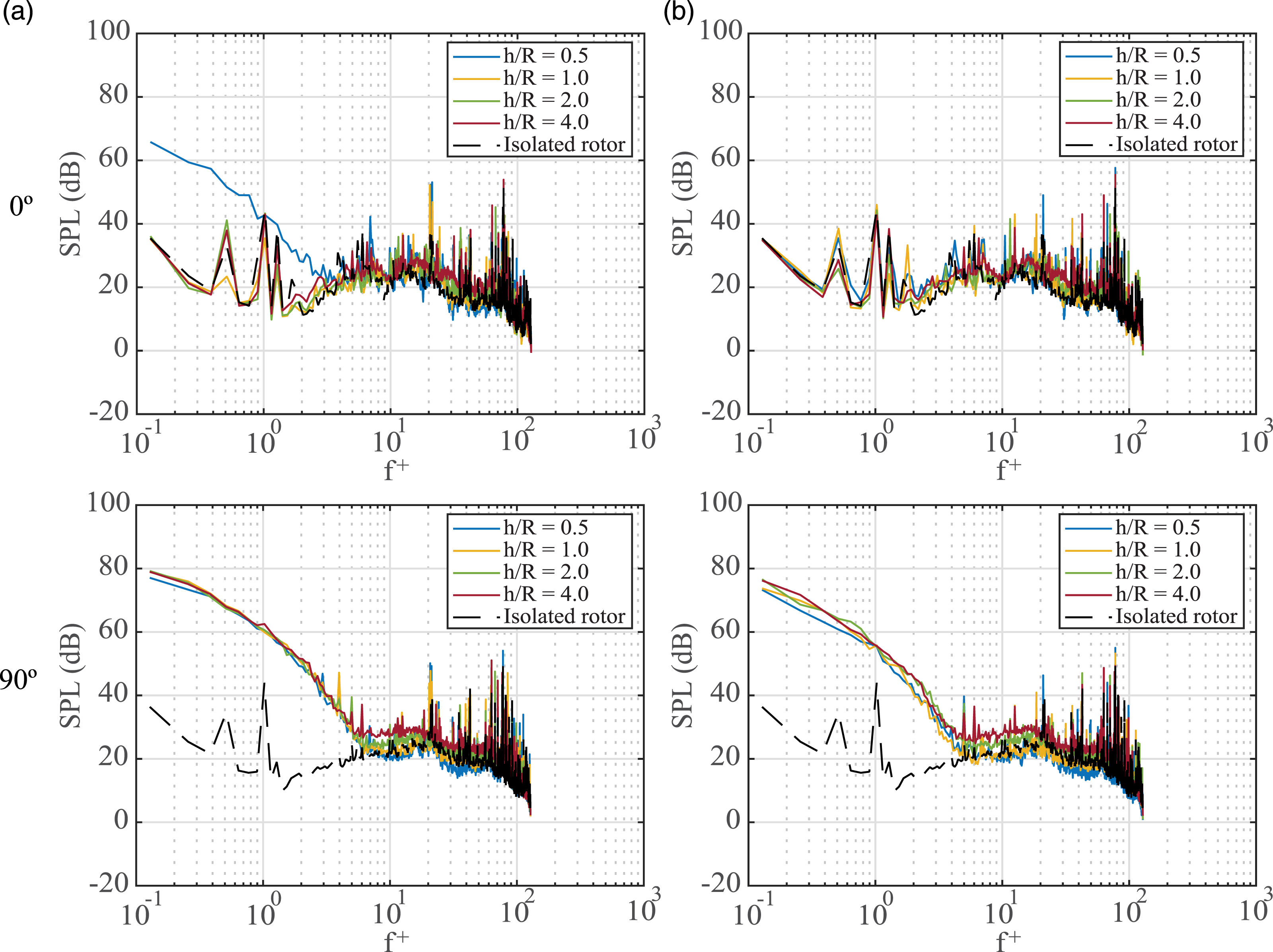
Influence of rotor rotation direction
The influence of rotor rotation direction on aero-acoustics is examined in this subsection. Figure 7 illustrates the same experimental scenarios outlined in the previous subsection, with the distinction that the rotation direction has been altered to counter-clockwise (CC). By juxtaposing Figure 7 with Figure 5, the outcomes manifest symmetrically along the chordwise centerline (0° - 180°), particularly evident in broadband noise and OASPL. The most pronounced fluctuations in noise at BPF are observed for the flat plate under opposite rotation direction. It is noted in Gojon et al
1
that tonal peaks at BPF, 2 x BPF, and 3 x BPF exhibit temporal variability for the isolated rotor, despite a consistent acoustic spectrogram. This temporal aspect could be a secondary reason for fluctuations in noise at BPF (the principal tonal noise at RPM 3,000). For both wings, the rotation direction exerts maximal impact at the 150° and 210° directions. As such, line plots of OASPLs at the 150° direction (depicted in Figure 8) for the two RPMs serve to assess the maximum influence of rotor rotation direction. In Figure 8, rotation direction yields a more substantial effect as the rotor approaches the wing, leading to a peak difference of approximately 9 dBA for the flat plate. The presence of wing curvature at the trailing edge (TE) worsens this effect by guiding the direction of the deflected rotor wake emanating from the NACA 0012 wing. The noise spectrum between (a) the flat plate and (b) the NACA 0012 wing at RPM 3,000 and in counter-clockwise (CC) direction. The line plots of OASPL between (a) the flat plate and (b) the NACA 0012 wing for RPM 3,000 and 3,600 at 150°.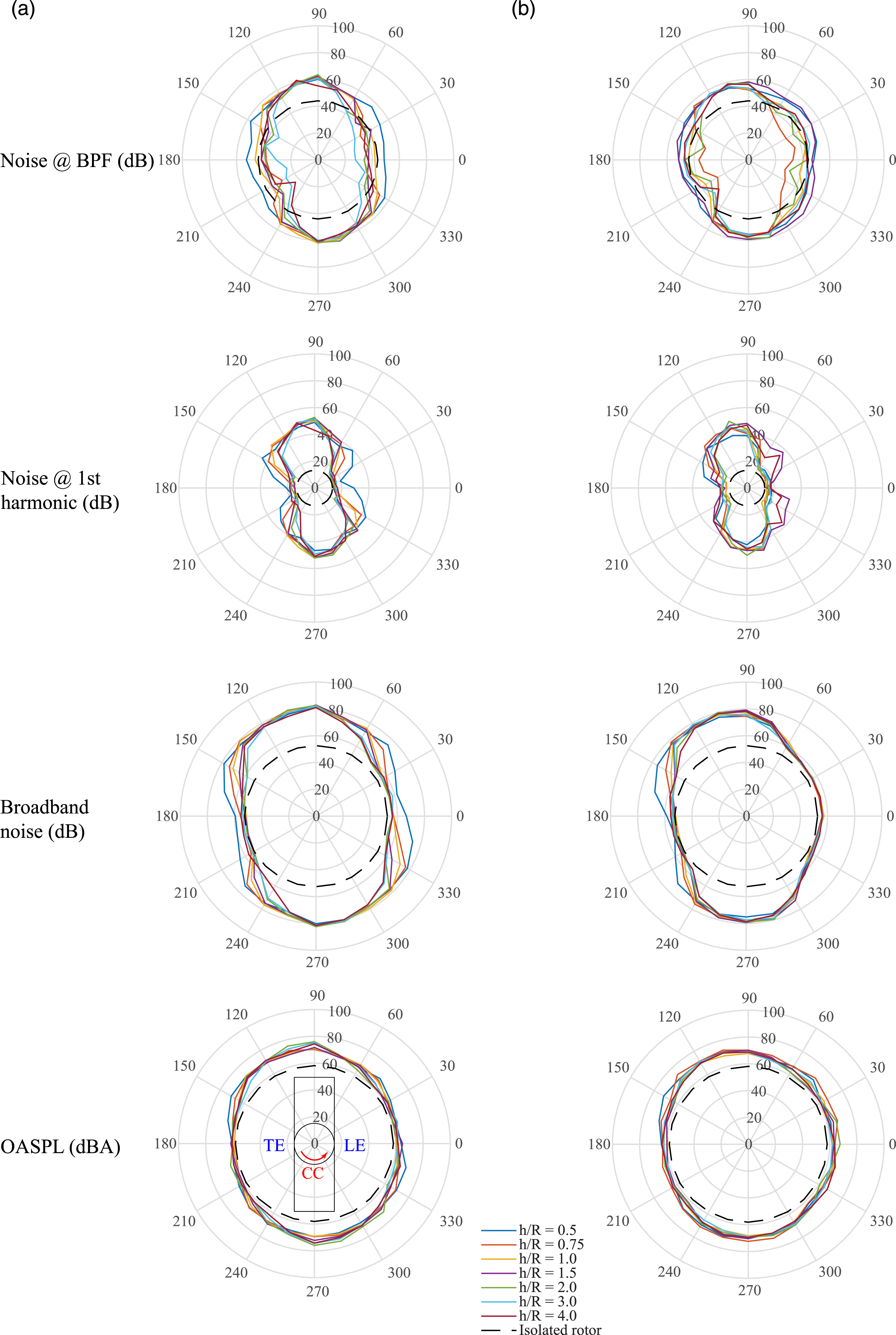
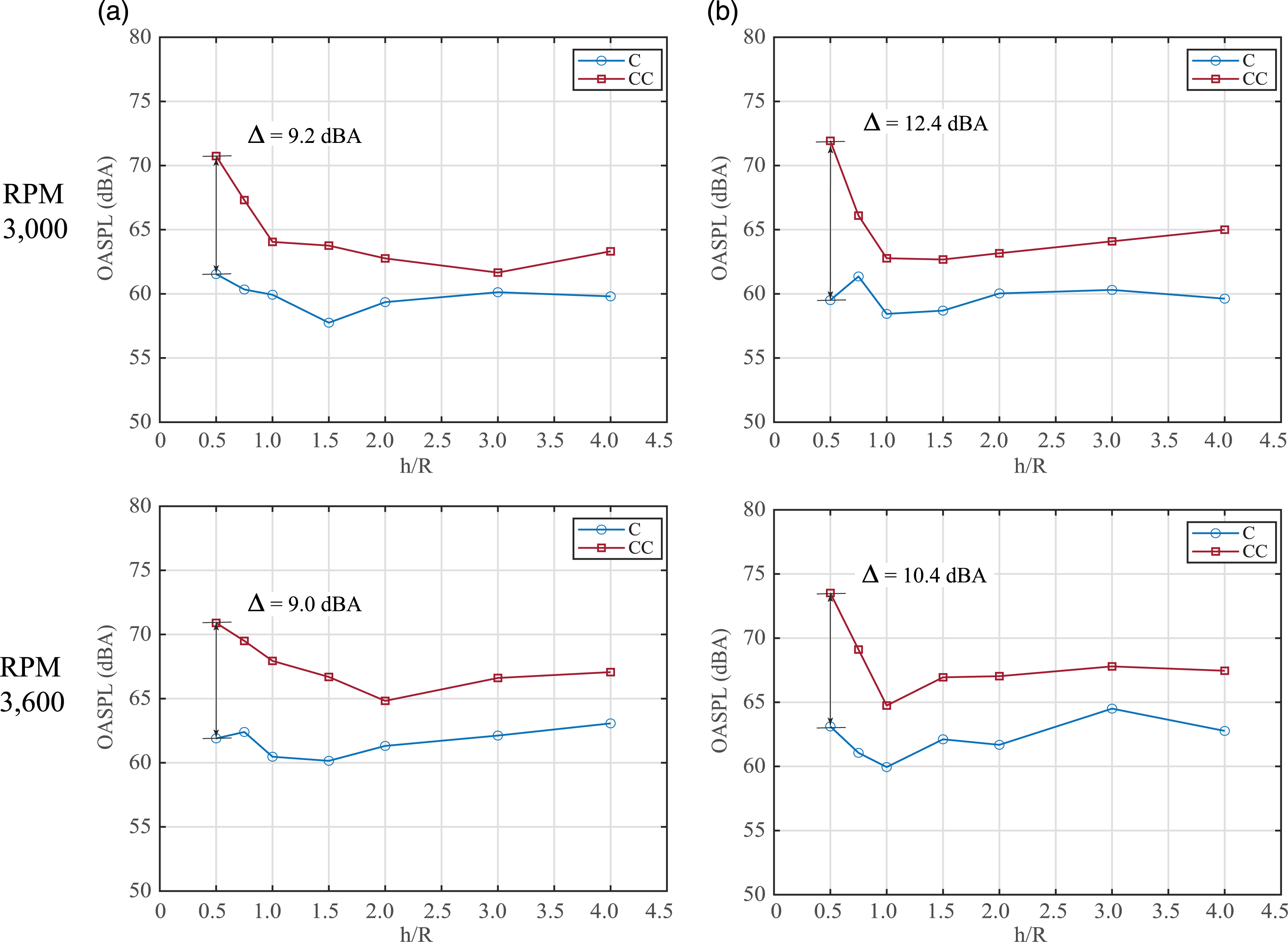
Regarding the NACA 0012 wing, if microphones are positioned at a lower height (distinct from the wing chord’s height), an amplified noise difference attributed to rotation direction might be captured. Rotation direction impacts noise directivity in rotor-wing interaction due to the relative alignment between the microphone and the tangential velocity component within the deflected rotor wake. If the microphone aligns with the tangential velocity component, a larger portion of the deflected rotor wake reaches the microphone. Furthermore, the strength of the deflected rotor wake determines how far it can propagate within the viscous air. In the experimental cases, the distance between microphones and the wing remains fixed. As the rotor approaches the wing, the deflected rotor wake intensifies. Consequently, the maximum OASPL difference occurs at smaller h/R values.
Influence of rotor RPM
Finally, we delve into the impact of rotor RPM on aero-acoustics. Figure 9 duplicates the experimental cases outlined in the initial subsection of this section, with the exception of an RPM increase from 3,000 to 3,600. The second row values of Table 4 are employed for the isolated rotor case (represented by dashed black lines). In comparison to Figure 4, the noise at 1st harmonics (2 × BPF) emerges as the principal tonal noise at RPM 3,600 for the specific rotor configuration. Notably from Figure 9, the noise at 1st harmonics, serving as the main tonal noise at RPM 3,600 for the isolated rotor, experiences varying increments or reductions across different directions and rotor heights—similar to the noise at BPF for RPM 3,000 in Figure 5. However, it’s worth highlighting that variations in noise at 1st harmonics are more pronounced for the NACA 0012 wing. Both Figures 5 and 7 underscore that rotor height and rotation direction exert minimal impact on noise levels at the 90° and 270° directions for both wings. The noise spectrum between (a) the flat plate and (b) the NACA 0012 wing at RPM 3,600 and in clockwise (c) direction.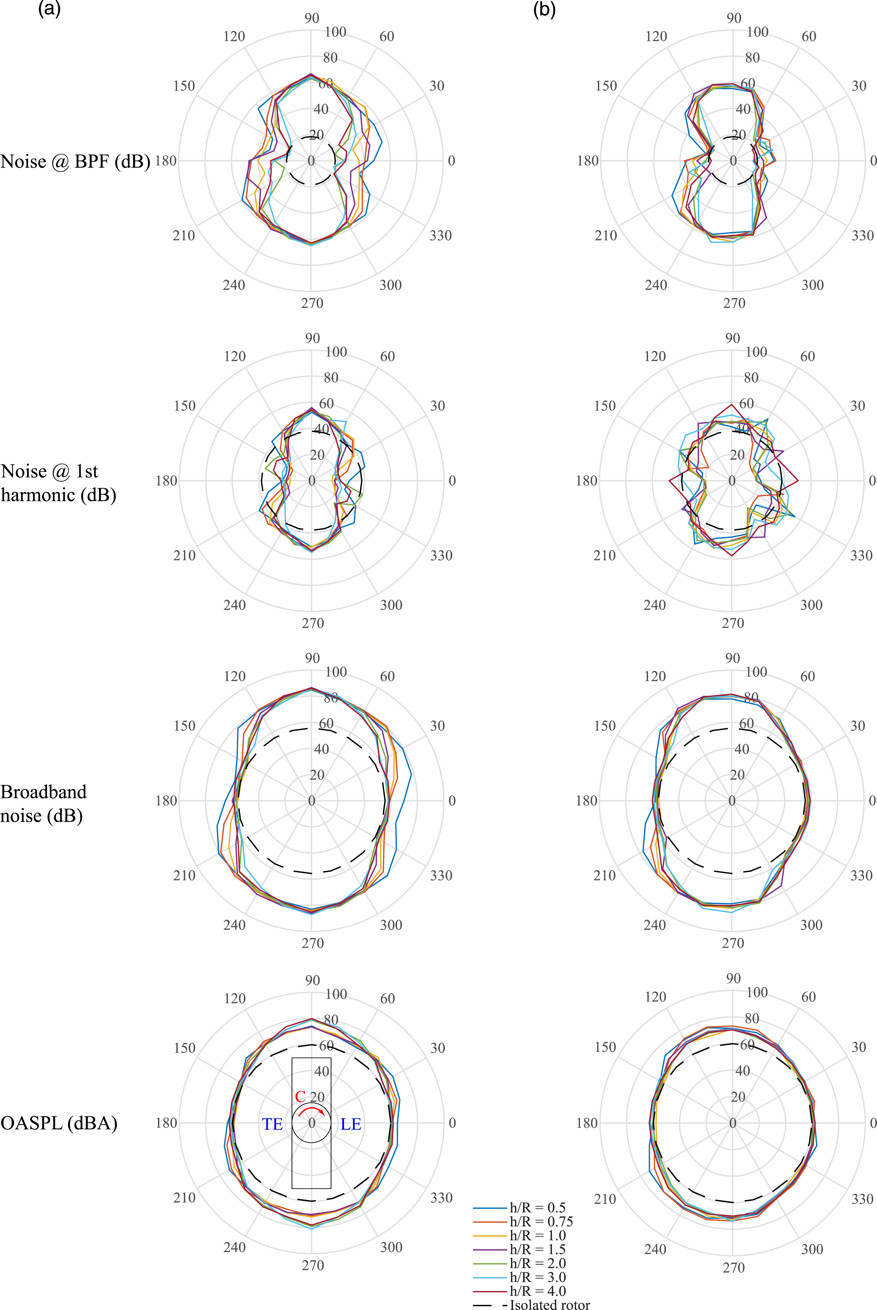
To more rigorously assess the impact of rotor RPM, OASPLs at 90° are graphed in Figure 10. The dashed black lines signify the averages of OASPLs for the two RPMs, even as OASPL decreases with decreasing h/R. From Figure 10, the averaged OASPL difference is less than twice greater than that of the isolated rotor (1.7 dBA in Table 4). This observation suggests that the deflected rotor wake tends to amplify the influence of rotor RPM in rotor-wing interaction. Furthermore, Figure 10 demonstrates that the NACA 0012 wing is less susceptible to the effect of the deflected rotor wake due to the wing curvature at the wing chord’s height. In other words, the wing curvature alters the spatial noise spectrum’s profile. However, this study does not delve into how it influences noise magnitudes (whether they increase or decrease spatially), as noise levels might change if microphones were positioned above the wing chord’s height, compared to the flat plate scenario at 90°. To mitigate noise levels in rotor-wing interaction, reducing rotor wake interference or diminishing the deflected rotor wake’s strength emerges as a viable strategy, in line with suggestions by Marte and Kurtz.
3
The line plots of OASPL between (a) the flat plate and (b) the NACA 0012 wing for RPM 3,000 and 3,600 at 90°.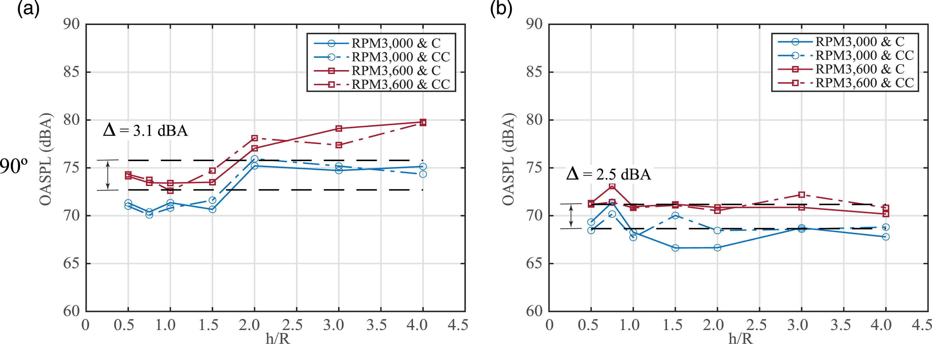
Conclusions
This paper meticulously investigates and quantifies the impact of rotor height, RPM, and rotation direction on aero-acoustics within single-rotor/wing interaction under conditions of low disk loading (25–35 N/m2 at far field) and low Reynolds number (57,000–69,000). The study employs two wing types—a flat plate and a NACA 0012 airfoil—both possessing an aspect ratio of four. The rotor diameter aligns with the wing chord. Acoustic measurements are collected using four microphones placed at a distance of three times the rotor diameter from the rotor center radially, situated in an anechoic chamber. By rotating the microphones at 15° intervals using a rotation stage, the directivity of the aero-acoustic field is assessed. It’s important to note that microphones are placed exclusively at the wing chord’s height. Prior to delving into the primary aero-acoustic experiments involving rotor-wing interaction, the paper analyzes potential flow recirculation effects within the anechoic chamber and isolated rotor noise.
Several notable conclusions emerge from observations and discussions of the experimental results: • Flow recirculation in the anechoic chamber yields negligible effects across the tested RPMs. • When RPM is adjusted from 3,000 to 3,600, the isolated rotor shifts the frequency of the principal tonal noise from BPF to 1st harmonic (2 × BPF). • In comparison to the isolated rotor’s noise signature, the deflected rotor wake in rotor-wing interaction markedly amplifies the broadband noise at low frequencies and OASPL. The presence and intensity of the deflected rotor wake determine whether the main tonal noise is reduced or eliminated. The most substantial increases are observed at the 90° and 270° directions (wing tips) for noise at BPF and 1st harmonic, broadband noise, and OASPL. Notably, variations are more pronounced in the main tonal noise compared to the broadband noise and OASPL. • Rotor height significantly impacts aero-acoustics, leading to substantial increases (at 30° and 210° directions), equalization (at 0° and 180° direction), and slight decreases (at 90° and 270° directions) in broadband noise and OASPL as the rotor approaches the wing and rotates in the clockwise direction. However, the flat plate experiences an increase at 0° direction when h/R = 0.5. • Rotor rotation direction influences noise directivity in rotor-wing interaction. A difference of around 10 dBA in OASPL is observed between clockwise and counter-clockwise directions at 150° when h/R decreases. This discrepancy may stem from the relative alignment between the microphone and the tangential velocity component within the deflected rotor wake, as well as the deflected rotor wake’s strength. • The impact of rotor RPM is amplified for both wings at 90° and 270°, although it remains less than twice as pronounced in terms of dBA unit, compared to the isolated rotor when RPM increases by 600 from 3,000, with regard to OASPL. • Wing curvature mitigates the impact of rotor height, rotation direction, and RPM at the wing chord’s height. However, the noise spectrum could potentially be amplified at other heights compared to the flat plate, since wing curvature guides the deflected rotor wake away from the wing.
In light of these findings, it is recommended to minimize rotor wake interference or reduce the deflected rotor wake’s strength to mitigate noise levels in rotor-wing interaction. It is noted that wing curvature might alter the spatial noise signature’s profile without necessarily affecting noise magnitudes. Future research will explore the aero-acoustic field within low disk loading and Re regime using tandem rotors in counter-rotation, both with and without a wing beneath, to gain deeper insights.
Footnotes
Acknowledgments
The authors thank North Carolina State University for the use of the test facilities. The research is supported by the gift fund from Mechanical and Aerospace Engineering (MAE) at North Carolina State University. Mr. Vincent Chicarelli and Mr. John Paul A. Cantonwine in the machine shop of MAE department fabricated the parts for this study.
Declaration of conflicting interests
The author(s) declared no potential conflicts of interest with respect to the research, authorship, and/or publication of this article.
Funding
The author(s) received no financial support for the research, authorship, and/or publication of this article.