
Abstract
Low-cost airlines have significantly increased air transport, thus an increase in aviation noise. Therefore, predicting aircraft noise is an important component for designing an aircraft to reduce its impact on environmental noise along with the cost of testing and certification. The aim of this work is to develop a three-dimensional Boundary Element Method (BEM), which can predict the sound propagation and scattering over metamaterials and metasurfaces in mean flow. A methodology for the implementation of metamaterials and metasurfaces in BEM as an impedance patch is presented here. A three-dimensional BEM named as BEM3D has been developed to solve the aero-acoustics problems, which incorporates the Fast Multipole Method to solve large scale acoustics problems, Taylor’s transformation to account for uniform and non-uniform mean flow, impedance and non-local boundary conditions for the implementation of metamaterials. To validate BEM3D, the predictions have been benchmarked against the Finite Element Method (FEM) simulations and experimental data. It has been concluded that for no flow case BEM3D gives identical acoustics potential values against benchmarked FEM (COMSOL) predictions. For Mach number of 0.1, the BEM3D and FEM (COMSOL) predictions show small differences. The difference between BEM3D and FEM (COMSOL) predictions increases further for higher Mach number of 0.2 and 0.3. The increase in difference with Mach number is because Taylor’s Transformation gives an approximate solution for the boundary integral equation. Nevertheless, it has been concluded that Taylor’s transformation gives reasonable predictions for low Mach number of up to 0.3. BEM3D predictions have been validated against experimental data on a flat plate and a duct. Very good agreement has been found between the measured data and BEM3D predictions for sound propagation without and with the mean flow at low Mach number.
Introduction
Increased air transport has resulted in greater annoyance from aviation noise and it has become an important concern in the aviation sector. Therefore, predicting aircraft noise is an important component for designing an aircraft to reduce its impact on environmental noise along with the cost of testing and certification. A robust numerical method needed to develop that can predict the sound propagation in mean flow and large aircraft installations to meet future noise emission standards for aviation. 1 Similarly, new innovative methods are needed to be developed to reduce noise generated by aircraft. Recently, periodicity-enhanced metamaterials and metasurfaces have shown promising results for noise attenuation 2 but they have not been explored for aeronautical applications. 3 The work presented here focused on the development and validation of the Boundary Element Method (BEM), which is capable of predicting sound propagation through these innovative metamaterials and metasurfaces in mean flow. The predictions of sound propagation and scattering are one of the fundamental problems in computational acoustics. BEM 4 has been widely used in acoustics due to its significant computational advantage over Finite Element Method (FEM) and Finite Difference Method (FDM), where the need to discretise the whole domain in contrast for discretising only the boundaries. BEM has already been extensively used to study the sound propagation over metamaterials for outdoor noise and room acoustics. However, its application for metamaterials in the aero-acoustics domain is still limited. The aim of this work is to develop a three-dimensional BEM, which can predict the sound propagation over metamaterials and metasurfaces in uniform and non-uniform mean flow for aeronautical applications. Particularly, for certification purposes, the focus is to develop a numerical method that can predict at a low Mach number of up to 0.3, where the aircraft is either at take-off or landing position.
In the last four decades, besides other applications, BEM has been extensively used in studying environmental noise propagation and attenuation. 5 Daumas, 6 Seznec, 7 Chandler-Wilde and Hothersall 8 were the first few authors who study the environmental noise attenuation by noise barriers using BEM and also proposed some modifications. 9 Since then it has been used extensively used for various types of environmental noise predictions until present day. 10 So far, the traffic noise attenuation by metamaterials and metasurfaces have been successfully modelled and well understood using BEM. 11 However, BEM application to study metamaterials and metasurfaces in the aero-acoustics environment is still limited 12 and interest has grown recently due to observed potential of these innovative materials in noise attenuation.
Historically, the aircraft noise attenuation received significant attention in the era of loud turbojet-powered aircraft and Concorde aircraft. 13 Recently, the interest in aviation noise attenuation has grown due to new concepts for Open-rotor fuel-efficient engine design and a significant rise in the self-driving taxi (eVTOL aircraft) and delivery drones. 14 Therefore, there is a need for the development of new innovative methods for noise attenuation. Thus simulation tools needed, those can predict the aerodynamically generated noise and its scattering in mean flow 12 through these complex structures such as metamaterials and metasurfaces. Lighthill 15 , 16 was one of the pioneers, who proposed a successful acoustics analogy theory to use an acoustically equivalent source term to represent propagation in the complex aero-acoustic environment. Later on, Williams and Hawkings 17 famously extended the Lighthill 15 , 16 theory to the prediction of aerodynamic noise from moving sources. Recently, the problem has been solved by Lorentz transform, which reduces the convected wave equation with the uniform flow to the standard Helmholtz equation. 18 In literature, the convected wave equations with the uniform mean flow have been used to solve various aero-acoustics problems. 19 A space-time Lorentz transformation was studied for aeroacoustic problems using Geometric Algebra. 18 Similarly, the jet noise diffraction was modelled 20 in mean flow using Lorentz-type transformation. A solid-surface boundary condition for acoustic scattering by rigid bodies with a uniform flow is given by the Prandtl-Glauert-Lorentz transformation. 21 , 22 The boundary integral solution for the convective wave equation in uniform mean flow is well established18–20, 22 and various modification has been proposed for non-linear scattering by moving bodies. 23 , 24 However, the inclusion of flow-induced noise in Boundary Integral Equation is essential for a wide range of aeronautical applications. 25 , 26 The effect of non-uniform potential flow and flow-induced noise can be taken into account by well-known Taylor transformation. 27 , 28 Taylor’s transformation is a simple time transformation that decouples the mean-flow and acoustic-field calculations and is valid under assumptions of low Mach number. 29 Recently, Agarwal and Dowling 30 show that Taylor transformation 31 , 32 is a viable solution to model uniform and non-uniform mean flow in BEM. Although, Taylor’s transformation is an approximation, but it’s the capability of implementing the impedance boundary condition and non-uniform mean flow make it preferable to be used for predictions over metamaterial. Therefore, Taylor transformation has been selected to implement the different types of metamaterials and metasurfaces in BEM and investigate their noise attenuation capability in mean flow for aeronautical applications.
For the last 10 years, the new concepts of acoustic metamaterials, and maetasurfaces have dominated the field of acoustics due to their ability to manipulate acoustic waves as never before and reviewed elsewhere. 2 , 3 , 33 , 34 Periodicity-enhanced metamaterials and metasurfaces are artificial structures with acoustic properties not found in nature and have already been proven in room acoustics 34 and in traffic noise attenuation 2 but they have not been explored for aeronautical applications. 3 Due to the advancement in 3D printing and the capability of making complex structures, there is an increased demand for studying the behaviour of sound propagation for new applications. 3 These innovative metamaterials and metasurfaces with the flexibility in shape, size and weight along with the capability of tuning to a specific frequency range, make them a strong candidate for aeronautical applications. The aim and novelty of this work are to tackle the challenge of simulation for complex acoustics structures such as metamaterials and metasurfaces in uniform and non-uniform mean flow for aeronautical applications. To evaluate the noise attenuation performance of metamaterials, these need to be simulated in mean flow. The metamaterials and metasurfaces are implemented as an impedance patch in a three dimensional BEM along with Taylor transformation. 31 , 32 In contrast to Lorentz transform, 18 which is an exact solution for uniform mean flow, Taylor’s transformation is an approximation. 30 The advantage of Taylor’s transformation is that it can be used to model both uniform and nonuniform mean flow, thus the flow-induced noise can be taken into account for the trailing edge. 25 , 26 The work presented here focuses on the development of three-dimensional BEM named as BEM3D along with Taylor’s transformation and methodology for the implementation of metamaterials. The BEM3D predictions have been benchmarked and validated against FEM (COMSOL) predictions and experimental data. The first section outlines the introduction, and then the development of BEM3D is presented. The ‘Validation: BEM3D’ section provides the BEM3D validation against the FEM (COMSOL) predictions and in the penultimate section, experimental data are discussed. Conclusions are drawn in section in the final section.
Development of BEM3D
BEM is a numerical computational method of solving linear Partial Differential Equations (PDE) that have been formulated as boundary integrals. The main idea behind BEM is that the solution to the PDEs can be obtained on the boundary and then that solution can be used to find the field at any point inside the domain by applying boundary conditions. BEM reformulates the PDE for an acoustic problem as a Boundary Integral Equation (BIE). The history of BEM goes back to 1903 when Fredholm 35 introduced the use of integral equations. However, they were not used until the development of modern computers which enables numerical calculations. Since then BEM has found applications in a number of fields, specifically in solving acoustics problems. As BEM is based on the discretization of boundaries, therefore the acoustics problems can largely be divided into two major categories: (a) Exterior boundary problems and (b) interior boundary problems. The interior boundary problems include applications such as room acoustics, 36 , 37 automobile acoustics 38 and internal body organs. 39
The exterior boundary problems have received more attention due to its capability of solving infinite domain by discretising only the exterior boundary and resulting application to a wider domain of acoustics problems, which is also the focal point of this paper. While solving the exterior boundary problems, the Helmholtz integral equation fails to provide a unique solution at some discrete frequency points corresponds to eigenfrequencies. 40 A number of different methods have been proposed to resolve the non-uniqueness problem for Helmholtz integral equation. 41 However, two are the most commonly used methods: (a) The most successful approach for solving the non-uniqueness problem was proposed by Schenck 42 and named as Combined Helmholtz Integral Equation Formulation (CHIEF), in which additional collocation points are used to create an overdetermined system of equations. (b) Burton and Miller. 43 The CHIEF method works well for low frequencies, 44 and not very reliable for high frequencies. However, Burton and Miller 43 method is reliable at all frequencies but doesn’t meet all continuity conditions and require higher computational recoruces. 44 According to literature, the CHIEF is a preferred method that has been applied to a wide range of acoustics applications 5 and also implemented in the BEM presented here. Nevertheless, the non-uniqueness problem is still the main area of research in BEM. 40 Similarly, a number of methods have been proposed to transform the integral equations into the boundary element methods, 5 but the most successful one in literature is proposed by Baker 45 in 1977 and named as collocation, which requires the representation of boundary as panels or mesh. 5 Moreover, the most widely used numerical integration in BEM for boundary integrals is Gauss-Legendre integration. 46
BEM is a useful tool for large acoustic problems at relatively high frequency, where other method failed to do so. 28 Similarly, there is a need for the development for BEM, which can simulate non-uniform mean flow problems along with resolving complex structures and geometries such as metamaterials and metasurfaces. 47 A three dimensional BEM named as BEM3D has been developed to solve the acoustics problems, which incorporates the Fast Multipole Method (FMM) 48 to solve large acoustics problems, Taylor transformation 31 , 32 to account for non-uniform mean flow, impedance and non-local boundary conditions for the implementation of metamaterials. BEM3D development is based on different libraries such as GNU Triangulated Surface library (GTS) 49 for geometry handling, the GNU scientific Library, LAPACK 50 for the iterative solver and the GLIB library for portability functions and special data structures.
BEM problem definition
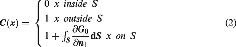
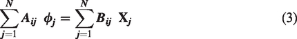
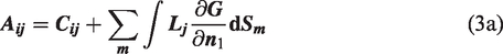
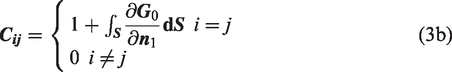
In order to study the sound propagation in the aero-acoustics environment, the boundary integral equations are defined in terms of Green’s function to solve Laplace and Helmholtz potential problems with applications in fluid dynamics
51
and in acoustic scattering
52
respectively. The integral equations for both Laplace and Helmholtz are identical, with only the Green's function being different. For an unbounded domain-containing surface(s)


The geometry
In BEM3D, the integrations in assembling the matrices are performed using quadrature rules for singular integrands, 53 Hayami's transformation for near-singular integrals 54 and the symmetric rules of Wandzura and Xiao. 55 The system is solved using a library, SISL, based on LAPACK. 50 The solver library allows for the parallel solution of problems using the MPI standard and also has a matrix-free option for use with fast-multipole methods. 48 , 56
BEM3D configurations
Within the code of BEM3D, the elements are represented as a collection of triangles, based on the underlying GTS triangle data type. An element within BEM3D is defined as an element is composed of a list of triangles, a list of collocation points with their indices, a list of geometric nodes, interpolation functions for surface data and interpolation functions for the geometry. This approach allows nodes to be indexed independently on each element, to support discontinuities, while allowing the underlying GTS surface to be geometrically valid. The shape functions employed are polynomials and elements of order zero to three have been developed. Similarly, a mesh is implemented as a GTS surface supplemented with a list of elements, a lookup table connecting elements to triangles and a lookup table connecting collocation points to their indices.
An important practical point in applications such as aerodynamics 57 where the imposition of an edge condition can be difficult and will ideally be performed without user intervention. BEM3D has developed a method to solve the sharp edges in aeroacoustics problems by automatically detecting and indexing sharp edges. In BEM3D, if a node is shared with adjoining elements, the surface normal at the node is computed on all of the elements. If the angle between surfaces normal is less than some specified value, the surface is taken to be smooth and the node is given one index. Otherwise, it is given a different index for each normal which deviate from the reference normal by more than the specified tolerance.
BEM3D solves the problem using either direct or fast multipole method as specified and uses the main BEM3D library along with other libraries such as WMPI, a set of wrapper functions for interfacing to MPI, SISL, interactive solver library and GMC.
Accelerated BEM3D: Fast multipole method
In terms of computation cost the BEM is computationally less expensive as compare to FEM, especially in case of exterior boundary conditions, where only boundaries need to discretized and it automatically meets the Somerfield radiation 40 conditions for an infinite domain. However, when solving for larger bodies and for multiple frequencies, the BEM becomes computational expensive as it numerically solves for each frequency. 5 Therefore, some methods have been proposed to speed up the computation, out of which the Fast Multipole Method (FMM) 48 is the most popular one and also implemented here. The FMM-BEM implementation can significantly reduce the computational cost 56 from O(N2) to O(N), where N is the number of iterations.
Since its introduction, the fast multipole method has been used by a number of researchers to accelerate the boundary element and to reduce its memory requirements. 48 , 56 The standard approach of direct solution of the matrix system has time and memory requirements which scale as N2, which quickly exceed the resources available on even the most powerful computers. The method implemented in BEM3D allows problems to be solved directly on parallel systems using the MPI standard, but it was considered better to implement a fast multipole method for the solution of problems and for calculation of radiated fields. The fast multipole method was originally developed for point sources, rather than elements of finite extent, and is usually implemented using spherical harmonics. In the method implemented in BEM3D, the basis algorithm is similar to the original adaptive fast multipole method, 58 but with two important differences. The first is the use of Taylor series in place of spherical harmonics, as used by Tausch in his non-adaptive method, 59 in order to cater for a wide variety of Green's functions. The second is a convergence radius criterion for the near field, an idea developed 60 to allow for finite-size elements which may not be completely contained within a box of the tree decomposing the computational surface.
The fast multipole method in BEM3D is implemented with functionality of adaptively, by recursively decomposing the domain into a hierarchical tree structure. A fast multipole method works by replacing a list of elements with a set of multipole coefficients which can be used to compute the field. 29 This was originally done using an expansion of the field in spherical harmonics, but BEM3D uses Taylor series 59 expansions have been used since they allow the unified treatment of a range of Green's functions. 60 The derivative of the Green’s function is calculated using an efficient and stable recursive algorithm as explained by Taush. 59 BEM3D uses the convergence radius of the expansion method to differentiate between the near and far-field for the implementation of fast multipole method. 60 The computation of integrals in BEM3D can be accelerated by speeding up the matrix multiplications required for the solution by using local expansions of the field about the centre of each leaf node of the tree. The near-field contribution is precomputed and stored in a sparse matrix for re-use in the solution procedure and the expansion order is a function of depth in the tree. 59
BEM3D for aero-acoustic problems
The study of noise radiation from aircraft is an important problem, especially when it comes to design, testing and certification. 25 BEM ability to solve large scale problems at high frequencies led to the development of Boundary Integral Methods for sound propagation in mean flow. In literature, the problem of sound propagation in uniform mean flow is solved by Lorentz transform. 18 , 61 The Lorentz transform reduces the convected wave equation with the uniform flow to the standard Helmholtz equation without approximation. 18 In deformed physical space, where the boundaries are also deformed the application of boundary conditions becomes complicated. The Lorentz transform was further improved by Wu and Lee 62 to solved the boundary conditions in deformed physical space. Recently, Hu et al. 22 proposed a new approach for boundary treatment in deformed space, which is based on zero energy flux solid wall boundary condition. The work has been extended to apply the zero energy flux solid wall boundary condition using Prandtl-Glauert-Lorentz transformation to solve the convective wave equation in uniform mean flow. 21 The convected wave equations with uniform mean flow been used to study various aero-acoustics problems. 19 A space-time geometric framework for the interpretation of Lorentz transformation in uniform mean flow was studied to solve more complex aeroacoustics problems. 18 Similarly, the emission and diffraction of elementary jet noise sources in the presence of a uniform subsonic mean flow were investigated using Lorentz-type transformation. 20 The boundary integral solution for the convective wave equation in uniform mean flow is well established18–20, 22 and various modification has been proposed for non-linear scattering by moving bodies. 23 , 24 , 63 However, the inclusion of flow-induced noise in Boundary Integral Equation is essential for a wide range of aeronautical applications. 25 , 26
The effect of non-uniform potential flow and flow-induced noise can be taken into account by well-known Taylor transformation. 27 , 28 Taylor’s transformation is a simple time transformation that decouples the mean-flow and acoustic-field calculations and is valid under assumptions of low Mach number. 29 Astley and Bain 64 proposed an approximate formulation for wave propagation in non-uniform mean flow based on Taylor transformation. 31 , 32 This formulation is only valid for mean flow at low Mach number. 64 Later on, a method based on Lorentz local transform was proposed to provide a viable solution for propagation in non-uniform mean flow. 29 However, it was only valid for mean flow fields with small gradients. Recently, Mancini et al. 65 proposed a new transformation which is based on the combination of both Lorentz and Taylor transformation, to provide an integral formulation for non-uniform mean flow. The proposed Taylor-Lorentz is an approximate formulation of the full linearized potential wave for isentropic compressible flows and only applicable to a weakly non-uniform mean flow. The weakly non-uniform means that the non-uniform part of the mean flow is small compare to the uniform one. 65 , 66 The Taylor-Lorentz transform prevents the use of impedance boundary conditions under the local mean flow affects. 67 Due to the fact that the Taylor-Lorentz is only applicable where the uniform mean flow is dominant and restricted the use of impedance boundary conditions. Therefore, it has been concluded that Taylor’s transformation is a preferable choice to study the sound propagation in non-uniform mean flow at low Mach number and where impedance boundary conditions are needed to be solved. Although Taylor’s transformation provides approximate solution, nevertheless Agarwal and Dowling 30 show that the Taylor transformation 31 , 32 is a viable solution to model uniform and non-uniform mean flow in BEM. One of the major advantages is that the impedance boundary conditions which is used to model metamaterials and metasurfaces in BEM can be implemented along with Taylor’s Transformation. Therefore, Taylor’s transformation has been selected to study the sound propagation over metamaterials and metasurfaces in the presence of uniform and non-uniform mean flow at low Mach number. Nevertheless, practically the calculation of noise propagation is mostly needed during the take-off and landing of an aircraft, where the Mach number is usually low of up to 0.3. Therefore, the focus of this work is to validate the BEM predictions at low Mach number.
Metamaterials implementation in BEM3D
Metamaterials and metasurfaces are artificial structures, which can absorb and dissipates sound as never before. These are new concepts and are already being applicable on room acoustics and traffic noise attenuation. However, their applications for aeroacoustics is still a question of research as it needs further development of lightweight structures, which can be applicable on aircraft without adding any extra weight. Similarly, the attenuation performance of already developed metamaterials and metasurfaces are strongly affected by mean flow, therefore these structures needed to simulate in aeroacoustics environment to test their performance.
The basic principles of metamaterials can be summarized in terms of equivalent values of averaged material parameters mass density ρ and bulk modulus κ where the effective values of these parameters can be modified, in some frequency range, by the choice of metamaterial operating principle and microstructure. Normal materials have ρ > 0, κ > 0 but by suitable choice of microstructure, one or both of the parameters can be made negative as far as acoustic propagation is concerned. In each case, this metabehaviour can be achieved by using a particular material structure and linear structural or acoustic operating principles. The unit cells for these metamaterials can be modelled using BEM and FEM packages. The acoustical parameters extracted from these unit cells are then used to create an impedance patch, which is then embedded into a flat plate and duct for simulations. The underline assumption here is that the acoustic response from an array of metamaterial unit cell to create a real structure is equivalent to an impedance patch modelled as reduced order with the continuum and the parameters extracted from the metamaterial unit cell. In these metamaterials, the underlying physics is acoustic propagation in some geometry which is designed to give anomalous behaviour at a surface. In other words, a complex structure is concealed underneath an otherwise “normal” surface such that the surface has non-standard acoustic properties. The nature of these properties is a function of the design of the underlying structure but does not require any microscopic fluid behaviour other than linear acoustics. This allows the unit cell, or basic unit, of the metamaterials to be designed using standard acoustic methods such as the BEM or FEM and the required properties of the unit cell to be extracted to find the continuum or mean properties which determine the macroscale acoustic behaviour.
The working assumption is that the basic properties of a unit cell can be extracted and used, in effect, as a reduced-order model to be integrated into a second computation which will yield the acoustic behaviour of a real structure which has been treated with a metamaterial composed of these unit cells. The calculation of the metamaterial, as distinct from the unit cell, the response thus requires the evaluation of non-local boundary conditions which represent the strongly coupled interactions which give the meta-behaviour which we seek. 68 The building blocks such as metamaterial’s unit cell characterization, impedance patch and non-local boundary conditions provide a method of implementation of metamaterials in BEM3D to carry out simulation in mean flow to test their performance for aeronautical applications.
Validation: BEM3D
A systematic benchmark study to validate the BEM predictions of metamaterials and metasurfaces in mean flow is needed. 28 Therefore, a set of benchmark problems have been defined to evaluate the performance and validity of BEM3D predictions for sound propagation over a flat plate, duct, and metamaterials with uniform and non-uniform mean flow. A commercially available simulation package, COMSOL (Finite Element Method (FEM)) have been used to validate these benchmark problems. BEM3D simulations are finally compared with experimental data. Initially, the simulations were focused on acoustically hard wall flat plate and rectangular duct with and without mean flow. The work has been extended to embed the metamaterials into flat plate and duct. Initially, the unit cell of the metamaterials was modelled as a detailed geometrical structure using BEM/COMSOL to extract the representative parameters and then these parameters were used to define an impedance patch which was integrated into the flat plat and duct respectively. The last step is to integrate the non-local boundary conditions to these impedance patches to close the loop.
FEM COMSOL predictions
COMSOL® is a commercial package used to validate the simulation results from BEM3D. COMSOL® multi-physics provides an interactive environment for modelling and solving acoustical problems based on the solution of Partial Differential Equations (PDE) using a Finite Element Method (FEM). It is based on the concept of dividing the complex geometries into small areas called subdomains. The solution for each subdomain is obtained by solving PDE. The acoustic module has a capability to simulate acoustic propagation and scattering as well as the propagation in mean flow with different Mach number.
FEM (COMSOL) predictions have been validated against experimental data 69 and AcouSTO, 70 which is a BEM developed at Rome Tre University. 71 A convergence analysis was carried out for COMSOL simulations to obtain accurate predictions. The meshes were refined and optimized until no change was observed in sound pressure level plots with further mesh refinement. The validated FEM (COMSOL) predictions were then used to study the benchmark problems.
Description of benchmark problems
The benchmark problems were designed to represent an aero-acoustics environment in terms of geometrical and operating conditions. Simplified geometries have been selected on which metamaterials are embedded to simulate and test their acoustical performance with and without mean flow. Two fundamental geometries that have been selected for benchmark studies are.
A flat plate model, representing a wing of aircraft based on NACA 0012 airfoil.
72
A rectangular duct model.
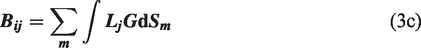
The schematics for flat plate and rectangular duct used for benchmark study to validate the BEM3D predictions are shown in Figure 1. For flat plate simulations, a total number of twelve source positions were used in the x-y direction. Along x-axis the source was placed at −0.1 m, 0.0 m, 0.1 m, 0.2 m, 0.3 m and along the y-axis the source was placed at a height of 0.05 m, 0.1 m and 0.2 above the flat plate. A circular microphone array with a radius of 1.0 m was used with a flat plate at the centre of the circle and a linear array with a length of 2.0 m was placed in front of the flat plate along the y-axis (see Figure 1(c)). For rectangular duct simulations, two source positions were used, one in the centre (x = 1.0 m, y = 0.0 m) of the duct and one at the upper surface of duct wall (x = 1.0 m, y = 0.38 m). A circular microphone arc array with a radius of 1.75 m and centre at the duct exhaust was used for simulations. Similarly, two linear microphone arrays, one horizontal along the x-axis and other vertical along y-axis were used as shown in Figure 1(d). Four frequencies such as 600 Hz, 1000 Hz, 2000 Hz and 4000 Hz have been selected in this study. The mean flow has been assumed along the positive x-axis with Mach number of 0.06, 0.1, 0.12, 0.2 and 0.3. Although, the simulations have been carried out for all scenarios as given, however, the results only for representative cases are presented.
Schematics to represent the geometries and source-receiver positions used to study the benchmark problems to validate BEM (a) Flat plate geometry (b) Rectangular duct geometry (c) Source positions over flat plate are shown by red solid circles; the circular array microphone position with a radius of 1 m with flat plate at the centre of the circle; and linear array microphone in front of the plate (d) Source positions inside duct is shown by red solid circles; the circular arc microphone with a diameter of 1.75 m; two linear microphone arrays, one vertical and one horizontal array.
BEM simulation results for flat plate – Hard wall
The first set of simulations were carried out for hard wall flat plate with and without mean flow. Although, the simulations were carried using 12 different source positions, but the results only for one source position (x = 0.0 m, y = 0.1 m, z = 0.0 m) is presented here as all other source positions give more or less identical conclusion. Similarly, four frequencies such as 600 Hz, 1000 Hz, 2000 Hz and 4000 Hz were used for simulations, but the results only for 600 Hz are given here as other gives similar results. BEM3D predictions for sound propagation in mean flow have been carried out using Taylor transformation, 31 , 32 which is an approximation. 30 The aim of this work is to validate the BEM3D capability of simulating sound propagation in mean flow using Taylor’s transformation. Although, Taylor’s transformation can be used for both uniform and non-uniform mean flow. However, for validation purposes, the simulation with the uniform mean flow is presented here. This is due to the fact that a benchmark simulation needed against which the BEM3D simulation with Taylor’s transformation can be validated. It is well known that the exact solution for Lorentz transformation can be implemented using Boundary Integral equations.18–20, 22 Therefore, the FEM (COMSOL) simulation was first validated for uniform mean flow and given elsewhere. 69 , 70 The validated FEM (COMSOL) was then used to validate the BEM3D predictions for benchmark problems as defined above.
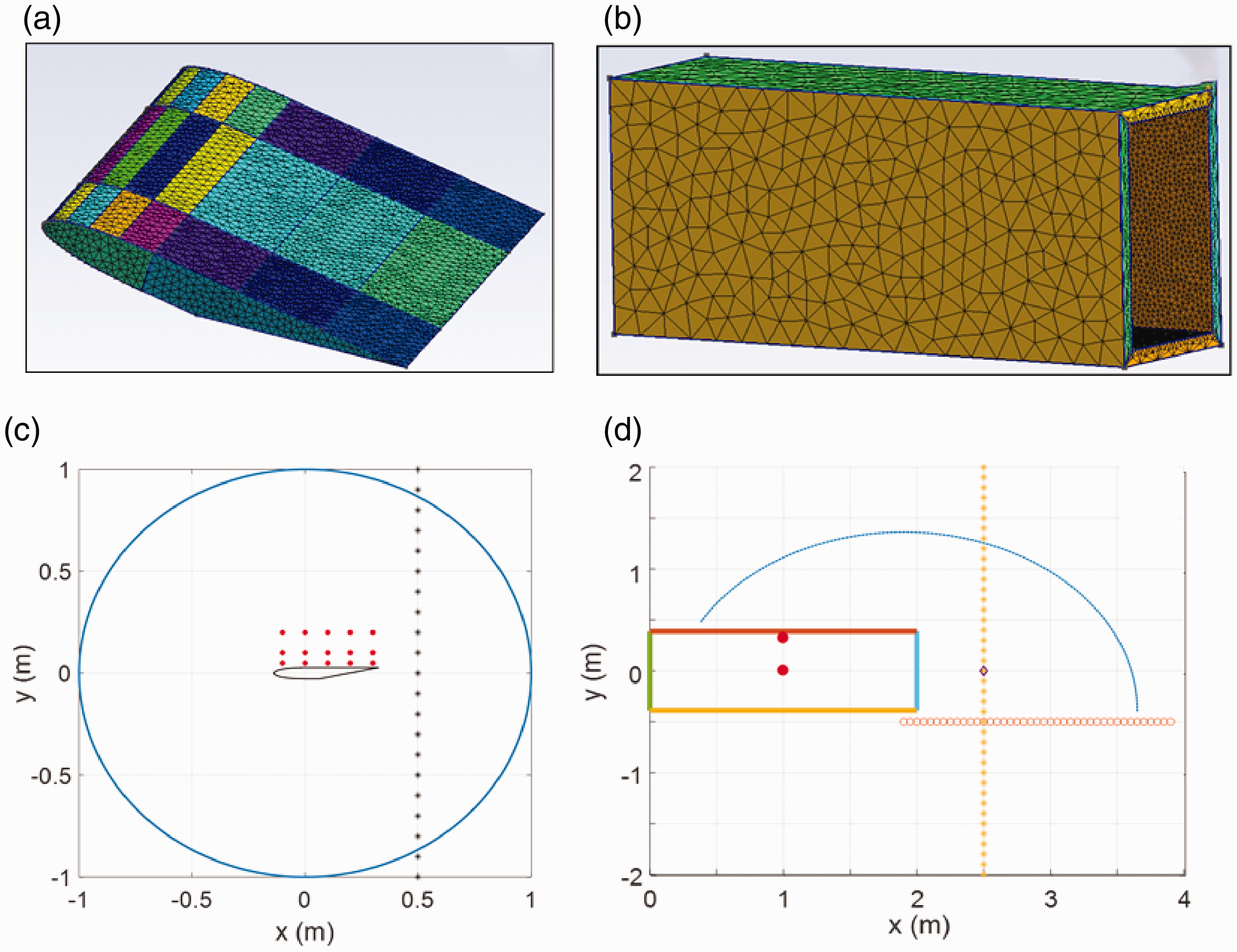
The comparison between BEM3D and FEM (COMSOL) predictions without and with the uniform mean flow at a frequency of 600 Hz is given in Figure 2. For no-flow case, the BEM3D and FEM (COMSOL) predictions are identical as shown in Figure 2(a) and (b). For Mach number of 0.1, the BEM3D and FEM (COMSOL) predictions show small differences as shown in Figure 2(c) and (d). The difference between BEM3D and FEM (COMSOL) predictions increases further for higher Mach number of 0.2 and 0.3 as shown in Figure 2(c) to (f). The increase in difference with Mach number is due to the fact that Taylor’s Transformation gives an approximate solution for the boundary integral equation. 30 Nevertheless, it has been concluded that Taylor’s transformation gives reasonable predictions for low Mach number of up to 0.3.
Comparison between predictions of BEM3D and FEM over hard-wall flat plate with source position at x = 0.0 m, y = 0.1 m, z = 0.0 m and circular microphone array, frequency = 600 Hz without flow (a) real (b) imaginary; with uniform mean flow (c) & (d) Mach number = 0.1 (e) & (f) Mach number = 0.2 (g) & (h) Mach number = 0.3.
Duct: Hard wall simulation results
The sound propagation through a rectangular duct has been carried out with and without mean flow. BEM3D simulations have been carried out by assuming both uniform mean flow and non-uniform mean flow (flow from inside the duct) by solving the Laplace problem to evaluate the aerodynamic field. Whereas, the FEM (COMSOL) simulations have been carried out only for uniform mean flow. For uniform case, the mean flow has steady flow in the domain, and for duct flow condition non-uniform inside the duct and almost stationary outside the duct. The calculations have been carried out for low Mach number of M = 0.1, M = 0.2 and M = 0.3.
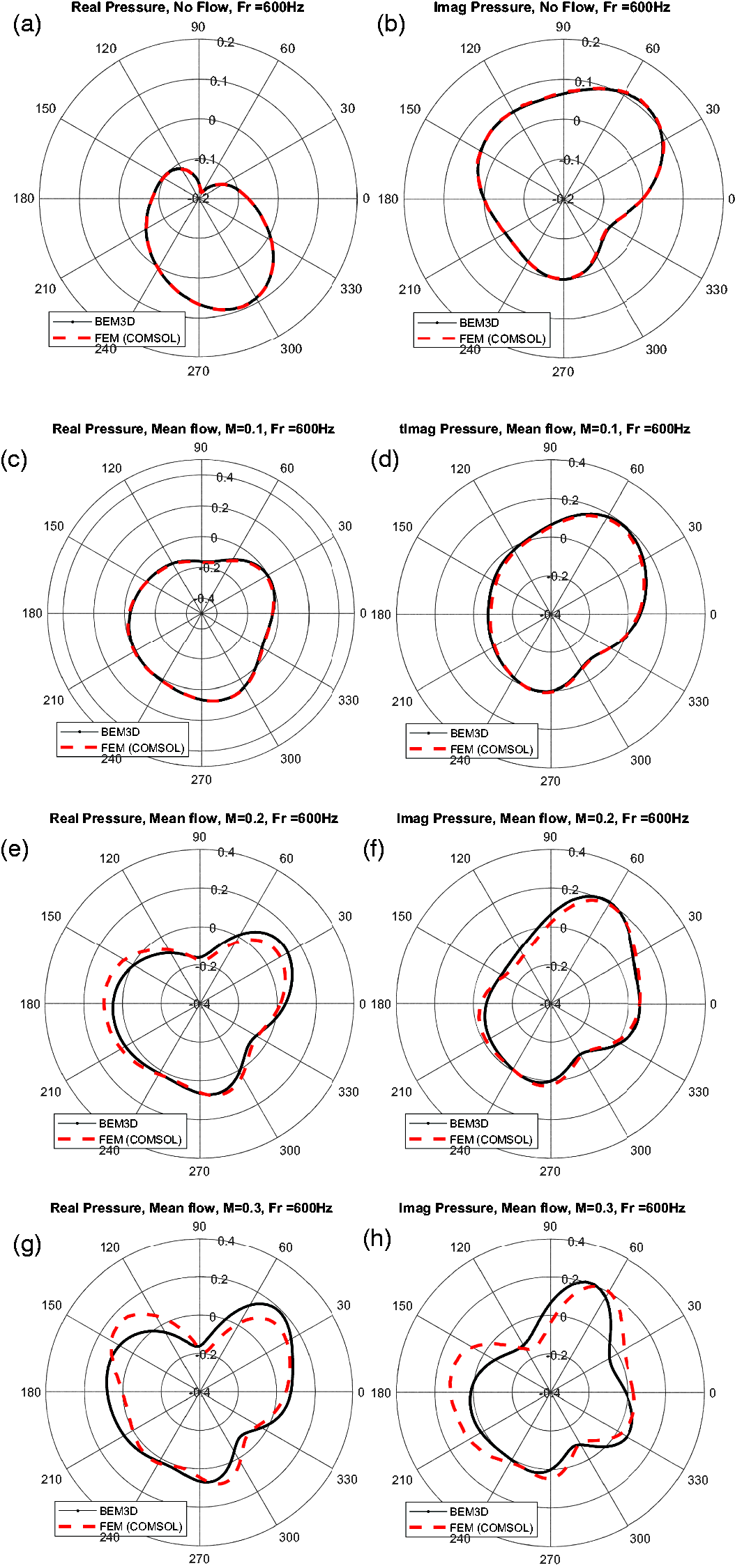
The simulations for rectangular duct have been carried using multiple source positions, but the results only for one source position (x = 1.0 m, y = 0.0 m, z = 0.0 m) is presented here as all other source positions give similar conclusions. Similarly, four frequencies such as 600 Hz, 1000 Hz, 2000 Hz and 4000 Hz were used for simulations, but the results only for 600 Hz are given here as other give similar results. The comparison between BEM3D and FEM (COMSOL) predictions with and without uniform mean flow at a frequency of 600 Hz is given in Figure 3. For no-flow case, the BEM3D and FEM (COMSOL) predictions are identical as shown in Figure 3(a) and (b). For Mach number of 0.1, the BEM3D and FEM (COMSOL) predictions show small differences as shown in Figure 3(c) and (d). The difference between BEM3D and FEM (COMSOL) predictions increases further for higher Mach number of 0.2 and 0.3 as shown in Figure 3(c) to (f). The increase in difference with Mach number is due to the fact that Taylor’s Transformation gives an approximate solution for the boundary integral equation. 30 Therefore, the Mach number of 0.1 show small differences between BEM3D and FEM (COMSOL) predictions and a Mach number of 0.3 show the higher differences. The predictions for duct flow boundary conditions deviate as non-uniform mean flow applied inside the duct.
Comparison between predictions of BEM3D (uniform and non-uniform mean flow (duct)) and FEM (uniform mean flow) for hard-wall rectangular duct with source position at the centre of the duct x = 1.0 m, y = 0.0 m, z = 0.0 m and microphone array arc, at frequency of 600 Hz without flow (a) real (b) imaginary; with mean flow (c) & (d) Mach number = 0.1 (e) & (f) Mach number = 0.2 (g) & (h) Mach number = 0.3.
BEM simulation for flat plate – Impedance patch
One of the fundamental aims of this work is to implement the metamaterial and metamaterials in three dimensional BEM to access their acoustic performance. The metamaterial and metamaterials are implemented as an impedance patch with the evaluation of non-local boundary conditions which represent the strongly coupled interactions which give the meta-behaviour which we seek. This is done, by extracting the equivalent impedance of the metamaterial unit cell. This equivalent impedance then used to model an impedance patch of same width as a metamaterial array of unit cells. The underline assumption is that the acoustical performance of full structural metamaterial unit cell or a metasurface (array of metamaterial unit cell) is similar to the acoustic response obtained through an impedance patch modelled by using the equivalent impedance parameters extracted from the metamaterial unit cell. The impedance patch with an equivalent impedance of the metamaterial is then simulated in an aeroacoustic environment to test its performance.
According to the definition for the impedance is,
71
Where
In BEMED the impedance is implemented as admittance,


A parametric study has been carried out for the sound propagation over impedance patch embedded in a flat plate to compare the prediction results between BEM3D and FEM (COMSOL). The arbitrary value of the impedance patch was varied from a very small value to a very large value in order to cover any retrieved value from the metamaterial characterization. The BEM3D predictions over impedance patch for all these impedance values were validated against FEM (COMSOL) predictions. The simulations have been carried out using different source-receiver positions. However, the results have been presented for one chosen source location at x = 0.0 m, y = 0.1 m, z = 0.0 m. All other source locations reached to more or less similar conclusions for one presented here. Moreover, the simulations have been carried out without and with the mean flow for low Mach number of 0.1, 0.2 and 0.3. Four frequencies of such as 600 Hz, 1000 Hz, 2000 Hz and 4000 Hz have been chosen for this study. The main aim of this study is to validate the capability of BEM3D for sound predictions over an impedance patch with and without mean flow.
The comparison between BEM3D and FEM (COMSOL) predictions over a flat plate embedded with an impedance patch, with and without mean flow, at a frequency of 1000 Hz is given in Figure 4. For no-flow case, the BEM3D and FEM (COMSOL) predictions are identical as shown in Figure 4(a) and (b). For Mach number of 0.1, the BEM3D and FEM (COMSOL) predictions show small differences as shown in Figure 4(c) and (d). The difference between BEM3D and FEM (COMSOL) predictions increases further for higher Mach number of 0.2 and 0.3 as shown in Figure 4(c) to (f). The increase in difference with Mach number is due to the fact that Taylor’s Transformation gives an approximate solution for the boundary integral equation. 30 Nevertheless, it has been concluded that Taylor’s transformation gives reasonable predictions for low Mach number of up to 0.3.
Comparison between predictions of BEM3D and FEM over flat plate with impedance patch for with source position at x = 0.0 m, y = 0.1 m, z = 0.0 m and circular microphone array, frequency = 1000 Hz without flow (a) real (b) imaginary; with mean flow (c) real, M = 0.1 (d) imaginary, M = 0.1 (e) real, M = 0.2 (f) imaginary, M = 0.2 (g) real, M = 0.3 (h) imaginary, M = 0.3.
Comparison between data and predictions
In order to test the BEM3D being developed, a set of acoustic experiments have been carried out at the University of Bristol’s wind tunnel test facility. The experiments were designed to carry out the testing in the aero-acoustics environment. The experiments have been conducted with a Bespoke nozzle with a one-meter long duct attached to it. The duct is made of 5 mm thick aluminium with a height of 775 mm and a width of 500 mm. The experiments have been carried out with and without metamaterials installed inside the duct. A BMS 4540ND speaker was used as a source inside the duct. The source was flush-mounted inside of the upper surface of the duct. The source is located at the end of the one-meter long duct which is connected with the bespoke nozzle. A microphone arc array was used to measure the sound propagation and scattering. The receiver arc consists of 23 microphones, with a radius of 1.75 m, centre of which was 0.29 m from the duct exhaust. The 23 microphones were placed at an interval of 5°, to cover an angular distance of 30° to 140° (see Figure 5(a)). The data has been collected with two test campaigns, with slight variations between the two.
(a) Schematic for wind tunnel measurement at the University of Bristol (b) First test campaign: Comparison between data measured at 600 Hz with BEM3D predictions by modelling nozzle as rectangular shape and Bespoke shape (c) Second test campaign: Comparison between data measured at 600 Hz with BEM3D predictions by modelling nozzle as Bespoke shape.
Figure 5(b) shows the comparison between data measured at 600 Hz with BEM3D predictions for the first test campaign. The BEM3D modelling has been carried out using two types of nozzles such as rectangular shape and Bespoke shape. It can be seen that the agreement between data and prediction improved for Bespoke nozzle as compare to a rectangular nozzle in the range of 60° to 90° angle. The microphones, which are placed behind the duct exhaust, i.e. > 100° angle, show disagreement between data and Bespoke nozzle predictions as shown in Figure 5(b). The higher sound level received behind the duct and disagreement between data and predictions can be explained by some sort of backscattering from the speaker directly towards the microphones, as confirmed by modelling a second source opposite to the inner source. An important point to note here is that the actual shape of the duct and nozzle plays an important role to determine the propagation of sound. Overall, it has been concluded that that BEM3D gives good agreement with measured data.
Figure 5(c) shows the comparison between data measured and BEM3D predictions for the second test campaign. The BEM3D modelling has been carried out using Bespoke shape as per the experiments. The agreement between the BEM3D predictions and data is good. Specifically, the agreement behind the duct exhaust, i.e. > 100° angle has been improved. This is due to the fact that the discrepancies such as source back-scattering has been removed, which was observed in the first test campaign.
The experiments were also carried out to study the sound propagation in mean flow. The experimental setup used was the same as given above and is shown in Figure 5(a). Figure 6 shows the comparison between experimental data in mean flow measured at 600 Hz and predictions using BEM3D and FEM (COMSOL). Figure 6(a) and (b) plot the real and imaginary part of sound pressure level measured with a mean flow velocity of 20 m/s and Figure 6(c) and (d) with a mean flow velocity of 40 m/s. The agreement between the measured data in mean flow is very good with both prediction methods as shown in Figure 6. BEM3D predictions were carried out using Taylor’s transformation with the assumption of the uniform mean flow. Although, Taylor’s transformation is an approximation, but the agreement with FEM (COMSOL) and data is very good for both mean flow velocities of 20 m/s and 40 m/s as shown in Figure 6(a) to (d).
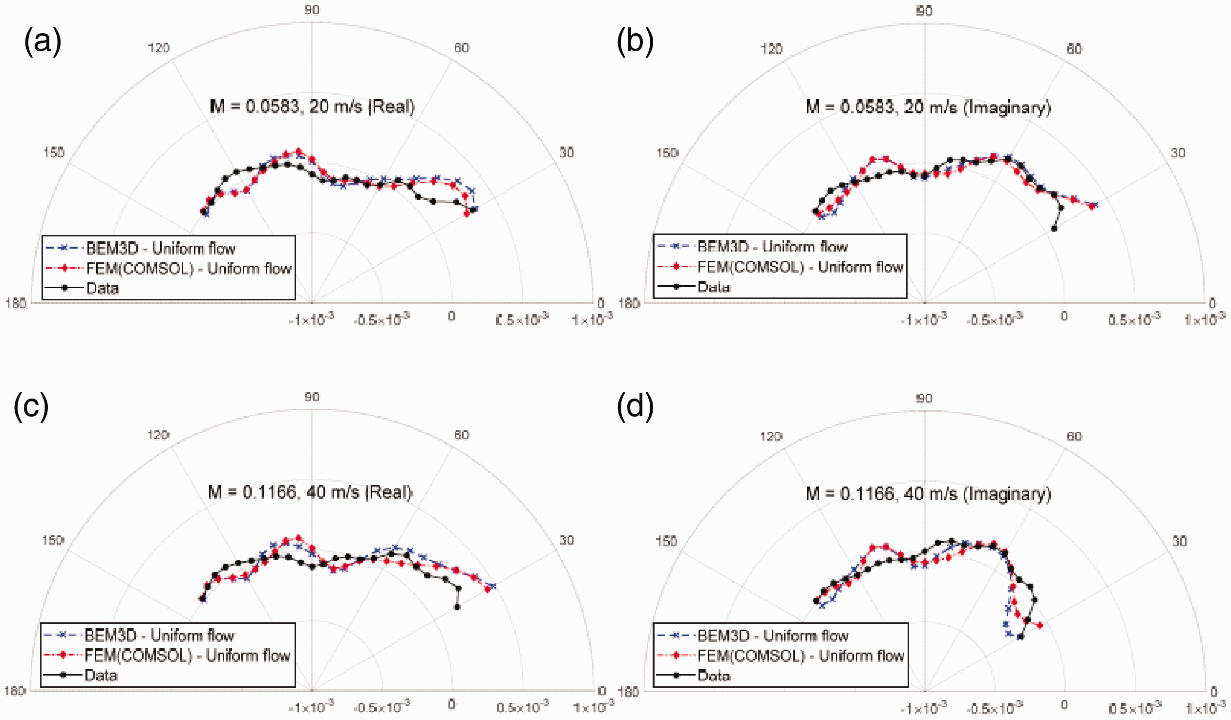
Comparison between data measured at 600 Hz with predictions carried out by BEM3D and FEM (COMSOL) for experimental setup shown as in Figure 5(a). The predictions were carried out by assuming uniform mean flow outside the duct. The data was collected for 1 m long duct connected with 1.044 m long Bespoke nozzle in mean flow (a) real, Mach number = 0.058 (b) imaginary, Mach number = 0.058 (c) real, Mach number = 0.1166 (d) imaginary, Mach number = 0.1166.
Conclusions
A three dimensional BEM named as BEM3D has been developed to solve the aero-acoustics problems, which incorporates the Fast Multipole Method (FMM) 48 to solve large acoustics problems, Taylor transformation 31 , 32 to account for uniform and non-uniform mean flow, impedance and non-local boundary conditions for the implementation of metamaterials and metasurfaces. The paper provides a methodology for the implementation of metamaterials and metasurfaces in three dimensional BEM. The building blocks such as metamaterial’s unit cell characterization, impedance patch and non-local boundary conditions provide a method for the implementation of metamaterials in BEM3D to carry out simulation in mean flow to test their performance for aeronautical applications. BEM3D predictions for impedance patch in the flat plate has been validated against FEM (COMSOL) predictions and experimental data.
In order to validate BEM3D, the predictions have been benchmarked against FEM (COMSOL) and experimental data. The benchmark problems were designed to represent the aero-acoustics environment in terms of geometrical and operating conditions. Two fundamental geometries have been selected, such as a flat plate and rectangular duct in order to investigate the capability of BEM3D being developed. A number of source positions have been used in this study, along with circular and linear microphone array to cover the whole spatial domain. For no-flow case the BEM3D and FEM (COMSOL) predictions are identical. For Mach number of 0.1, the BEM3D and FEM (COMSOL) predictions show small differences. The difference between BEM3D and FEM (COMSOL) predictions increases further for higher Mach number of 0.2 and 0.3. The increase in difference with Mach number is due to the fact that Taylor’s Transformation gives an approximate solution for the boundary integral equation. 30 Nevertheless, it has been concluded that Taylor’s transformation gives reasonable predictions for low Mach number of up to 0.3.
BEM3D predictions have been validated against experimental data on a flat plate and a duct. Very good agreement has been found between the measured data and BEM3D predictions for no flow case. Similarly, the measured data in mean flow shows a good agreement with BEM3D predictions using Taylor’s transformation. BEM3D predictions along with Taylor’s transformation have been validated, and it has been concluded that the BEM3D is a good tool to implement metamaterials and to simulate problems in the aero-acoustics environment.
Footnotes
Acknowledgements
The authors acknowledge the useful input for COMSOL modelling from Dr Lorenzo Burghignoli and Dr Giorgio Palma at Department of Mechanical and Industrial Engineering, Roma Tre University, Rome, Italy. The authors also acknowledge the useful discussion for propagation in mean flow with above mentioned colleagues at Roma Tre University. The authors acknowledge the measurement data as per provided by the University of Bristol, UK under AERIALIST.
Declaration of conflicting interests
The author(s) declared no potential conflicts of interest with respect to the research, authorship, and/or publication of this article.
Funding
The author(s) disclosed receipt of the following financial support for the research, authorship, and/or publication of this article:The research work is funded under the EU Horizon 2020 grant for AERIALIST.