
Abstract
In this study, the applicability, fuel saving and CO2 emission reducing potential of the triple heat-exchanger fed by the diesel generator exhaust gas with and without water steam have been studied for ship’s one and two main engines pre-heating and freshwater generation (FWG) cycles under port conditions with conducting energy and exergy analysis. The performance criteria (PC) and exergy efficiency (ε) values of the main engine pre-heating and freshwater generator systems of the Ro-Ro ship selected for the case study were determined by written Matlab 2021a codes merging CoolProp 6.4.2 database with Python. It was determined that even at the lowest operating load of the diesel generator (25%), the exhaust heat energy would be sufficient to preheat the main engine and generating fresh water with also saving fuel consumption. As a result, during the 12-h port period, each 1 kW heat energy reduction on steam will provide 0.0853 kg/h fuel saving in the boiler. Thus, 273 kg CO2 emission will be reduced for each kW of heat energy to be obtained. Considering the comparatively increased PC and ε values of whole system cycle containing common triple heat-exchanger for two main engines, it can be used conveniently and reliably on ships.
Keywords
Introduction
Due to increasing environmental and economic concerns, the demand for a green ship remains urgent. However, conventional fossil fuels consumed by main and auxiliary engines on ships still account for a large portion of operating costs and are also associated with a large proportion of engine exhaust gas emissions. 1 Although the 50% or more efficiencies of marine engines, a considerable amount of heat is lost, notably in exhaust gas emissions, in the cooling of the scavenge air, and, in the oil and jacket water coolers. 2 By converting existing ship waste heat into beneficial energy, Waste Heat Recovery (WHR), has already been recognized as an effective method to improve ship energy efficiency. Ship engines consume a substantial amount of fuel energy for propulsion and for this reason, theoretical, numerical, and applied studies have intensified in this field, which provides opportunities to save fuel and thus reduce CO2 emissions. 3 With the technologies available today, the thermal efficiency of low-speed ship engines can be increased up to about 55%, which is higher than that of land vehicles. 4
There are valuable studies related to energy recovery from main engine waste energy in the literature. The single-pressure steam Rankine cycle method for WHR from the main engine of a ship was proposed by Tien et al. 5 and compared with the theoretical calculations of ship test data. Mito et al. 6 have evaluated the performance of a single-pressure Steam Rankine Cycle (SRC) to recover scavenged air and exhaust gas heat from a ship main engine. They were obtained 5.1% efficiency increase and 9.7% fuel consumption reduction in comparison with dual pressure cycle. Hussein and Kandil, 7 analyzed the water production for a cruise ship using three different methods utilizing waste heat from diesel engine exhaust and jacket water. Fitri et al., 8 aimed to use the waste heat in the exhaust gas and cooling water system of the diesel engine in a 48 m long passenger ship as a water heater for heating the water to be used in passenger cabins. In order to reduce fuel consumption, MAN Diesel and Turbo 2 authorities are developing technologies to recover the waste heat energy of the main engines produced. One of them is a new type of economizer placed in the flue path of the generators to utilize the waste heat from the exhaust of ship generators.
As a result of the studies so far, it is seen that intensive efforts have been made to increase ship energy efficiency with cooling system and power system on ships. When we look at other studies where energy is needed, we see that there are oil and fuel heating, auxiliary boiler feed water heating, seawater desalination, desulfurization applications. We can evaluate the WHR System on board in many different applications. Shafieian and Khiadani 9 have presented a new coupled desalination, cooling, and air conditioning system to recover and apply waste heat from diesel engine exhaust gas and jacket water in submarines. Ouyang et al. 10 proposed a novel WHR system composed of a desalination unit and a two-stage renewable adsorption cooling device combined with the marine engine to meet the requirement of fresh water and cooling on ships by utilizing waste heat energy.
In the first movement of the ships, the main engine cannot suddenly reach the temperature values in operating conditions. Steam energy produced in the boiler is used for heating. Therefore, this situation causes more fuel consumption in the auxiliary boiler. There have been precious studies in the literature on waste energy recovery by utilizing ship main engine jacket water.11,12 However, there are not enough studies in the literature on both heating the jacket water when the main engine is in preheating and FWG line with waste generator exhaust gas energy at the same time. Moreover, in the last century, several research have conducted on the sophistication of the design and analysis of double-flow heat exchangers in several fields as well as in naval engineering. As evidenced by the results of several studies,13–15 the addition of a third fluid stream will certainly increase the difficulty of the design of this new type of heat exchanger. Therefore, the number of key factors related to the design, performance, and context of the study should be increased and analyzed for multiple flows.
The use of triple heat exchangers can potentially increase the efficiency of waste heat recovery compared to traditional dual heat exchangers. This is because triple heat exchangers allow for greater flexibility in the heat transfer process, with the ability to optimize heat transfer rates for different fluids and temperatures. Additionally, the use of triple heat exchangers can reduce the overall size and weight of the WHR system, which can be particularly beneficial for marine applications where space and weight are at a premium. There are especially several studies on design and fluid flow performance analysis of three-fluid heat exchangers.13,16–22 The thermodynamic and WHR studies in literature about triple heat exchangers are not more than two-fluid ones. The one of the first studies is by Sorlie 23 about developing a general theory for two temperature effectiveness of parallel and counter flow type three-fluid heat exchangers. Ruan et al. 24 were represented exergy effectiveness to emphasize the thermodynamic performance of three-fluid heat exchangers with three thermal interactions. Aulds and Barron, 25 were extended Sorlie’s study by determining an analytical interaction between the design variables. Due to the higher computational sophistication regarding the inclusion of other operating variables, a numerical method was adopted by Barron and Yeh 26 to obtain the temperature distribution and heat exchanger effect of counterflow three-fluid heat exchangers including the longitudinal conduction effect. Sekulic and Kmecko 27 have studied the performance of three-fluid parallel-flow heat exchangers based on effectiveness and compared four possible configurations of linking the flows with two thermal interactions. Willis and Chapman 28 have tried to graphically emphasize the performance of a three-fluid crossflow heat exchanger based on the temperature effectiveness. Sekulic and Shah 29 conducted a very in-depth review of methodologies for analyzing the steady-state analysis of the three-fluid heat exchanger. Yuan and Kou 30 have studied the entropy generation in a three-fluid crossflow heat exchanger in the existence of wall longitudinal transmission using a numerical method.
WHR studies utilizing the waste heat in the exhaust gas of the generator are quite abundant in the literature. However, there is no study on the fuel savings and CO2 emission reduction to be achieved in the boiler by preheating the ship main engine with exhaust gas. In addition, there is also no study on the feasibility of preheating two ship main engines using a single three-fluid heat exchanger proposed in this study and the benefits in terms of fuel savings and CO2 emission reduction. Therefore, what is proposed in this study is a novel concept. The originality of this study is to thermodynamically investigate the applicability of preheating of the main engine as well as freshwater generation by utilizing the waste energy in the exhaust gas of the generator by assessing WHR capability of double and triple heat exchangers, comparatively. This study was carried out on an RO-RO vessel with two main engines of type MAN 8S50ME-C9.5 and two generators of type MAN 9L21/31. The analyses are performed according to the first and the second law of thermodynamics with measured data from the ship. Since there is no energy production or consumption in the scenario cycles examined and only the heat entering and leaving the system is considered, the PC values of the system are taken into consideration instead of the energy efficiency of the system. Also, the exergy efficiency and the fuel saving values of the proposed method were determined.
Material and method
System description and validation study
About ship
The ship used in the study is a Turkish flagged RO-RO vessel. The vessel generally operates in Istanbul-Italy and Mersin-France voyage zones, as shown in Figure 1. The vessel spends an average of 12 h in both ports for the loading or unloading period. In addition, 72 h are spent for each of the average outbound and inbound voyage periods.
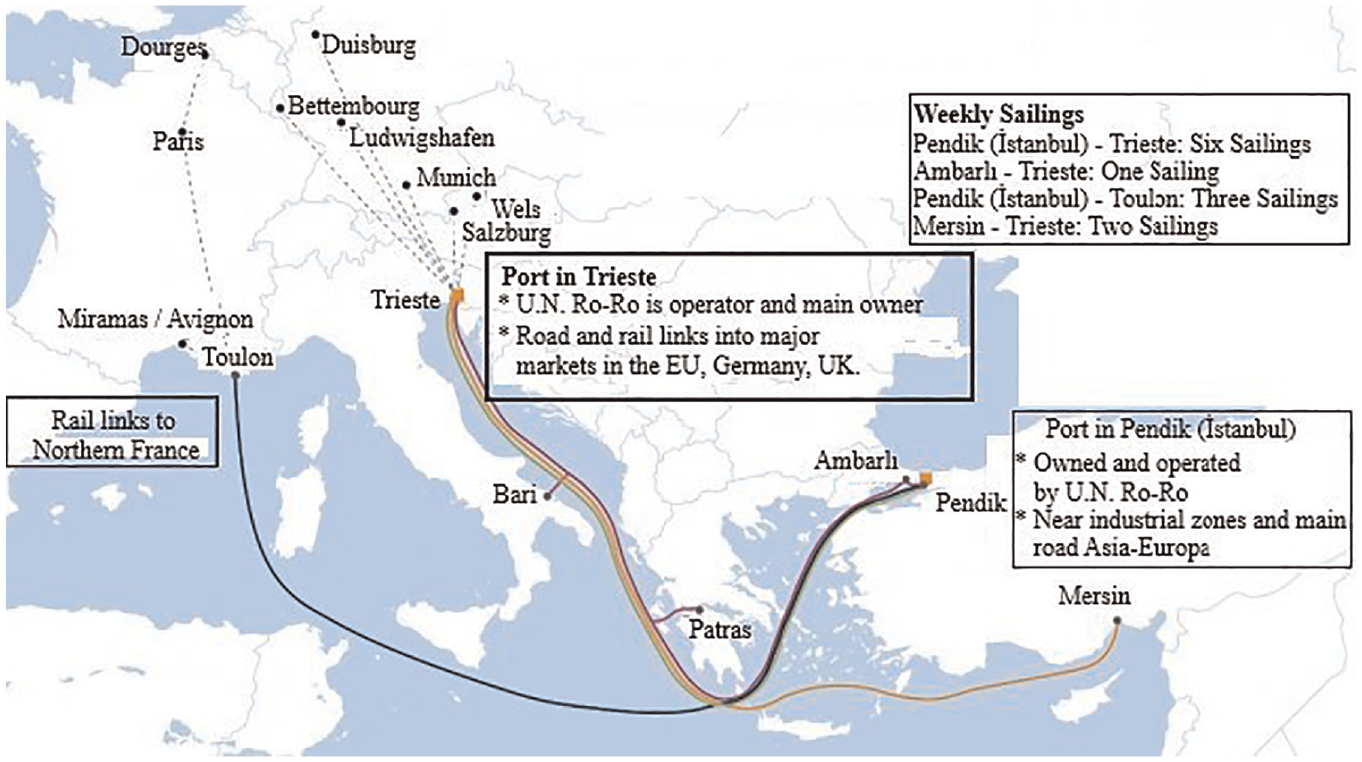
U.N. Ro-Ro network and ship’s voyage zones. 31
The total voyage time for 1 week is 144 h and the total port time for 1 week is 24 h. The data used in this study were obtained during the port processes of the ship’s Istanbul (Pendik) – Italy (Trieste) voyage. Main particulars of the ship were given in Table 1.
Ship main particulars.
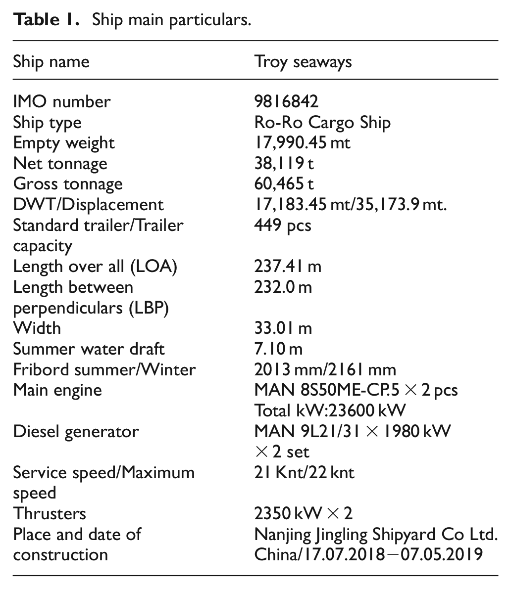
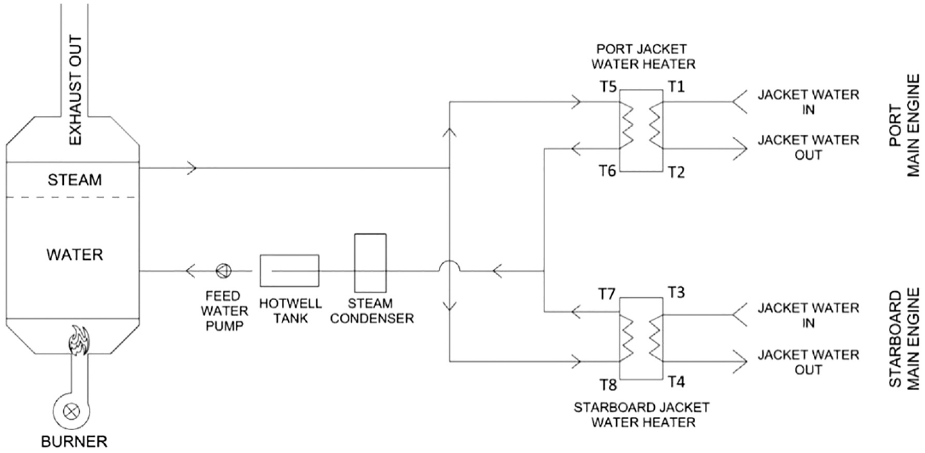
Figure 2 shows a schematic of the generators, boilers, propulsion system, and main engine cooling water of the ship from which the data is taken.
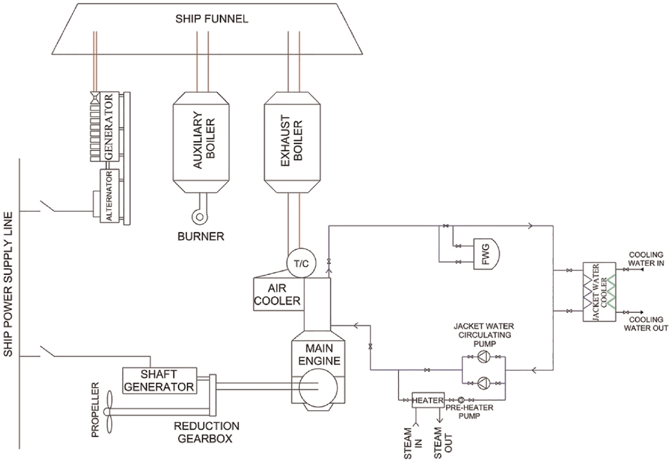
General plan of generator, main engine, cooling system, and boilers of the ship. 32
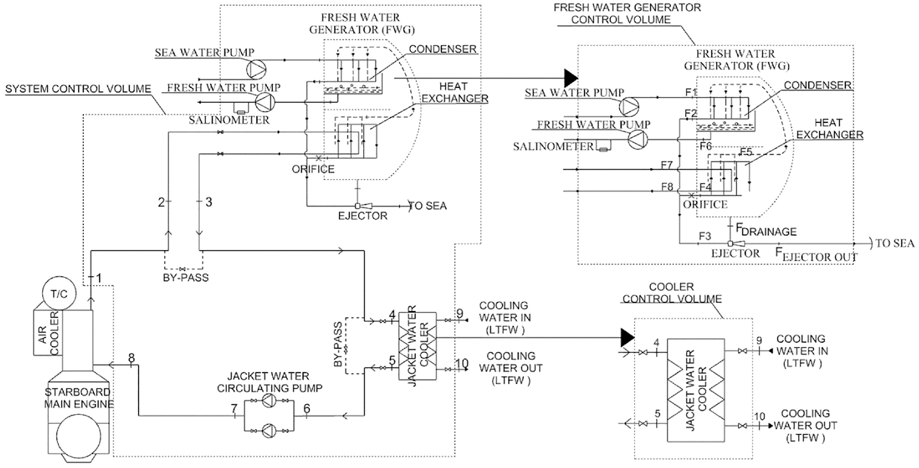
Therefore, when the main engine is running, the ship’s electricity needs are met through the shaft generator. When the main engine is not running, the ship’s electricity needs are met by diesel generators. There is a pressure value lower than atmospheric pressure in the FWG. Thus, the temperature above the jacket water is sufficient to evaporate seawater. 33 When the main engine is not running at the port, the engine is kept warm with preheating pumps and a heater using steam energy. In this study, a novel system has been proposed for the right-hand side of Figure 2. It has been reorganized for port application such as the generator exhaust gas is used instead of steam for pre-heater.
Main engine and auxiliaries
Technical specifications of the generators 34 and main engines taken from the user manuals are given in Table 2.
Main engine and diesel generator technical information.
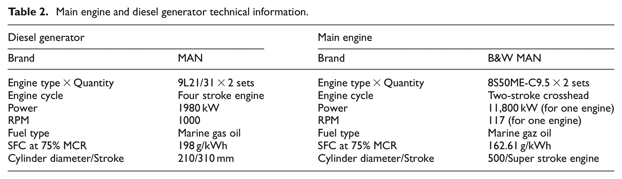
According to data from the operating manual for the MAN 9L21/31, diesel generator on board, at 100% load, 696 kW of the heat loss distribution of the generator comes from the exhaust. Technical information taken from the user manual of the Alfa Laval Aalborg OS-TCI 35 model, flue tube boiler on board is given in Table 3.
Auxiliary boiler technical information.
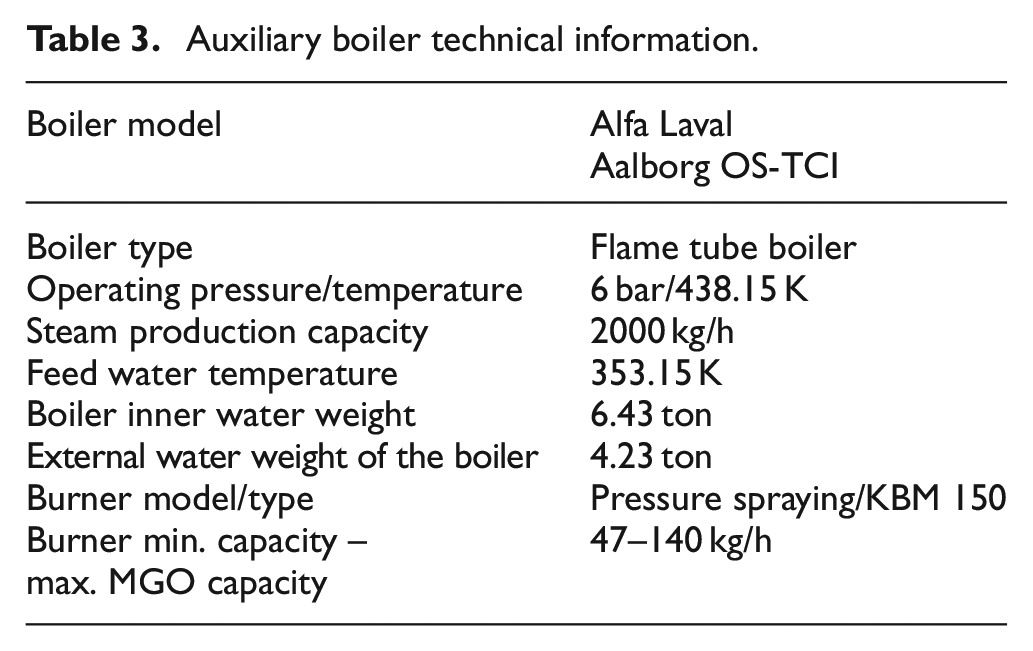
Figure 3 shows the cooling system diagram of a single main engine. Each main engine has an independent and identical cooling system. Preheat pumps and heater are off when the main engine is running.
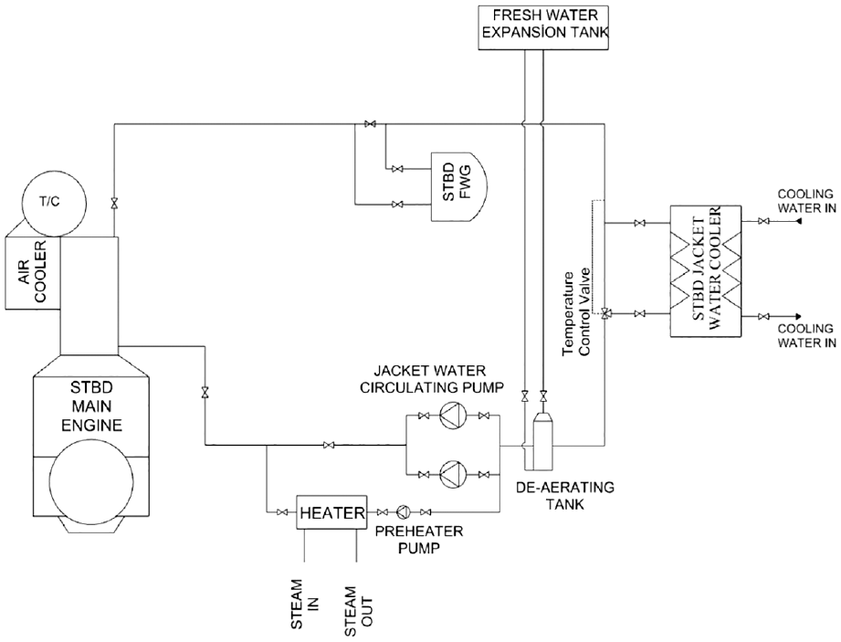
Schematic of the jacket water cooling system. 32
When the engines are not running, the cooling pumps are also not running. Instead of the cooling pumps, the preheating pump, which requires less power (∼4.9A/3 kW), is operated. In addition, while the preheating pump is in operation, the jacket water is also heated by the heater. While the preheating pump has a flow rate of 16 m3/h, the inlet and outlet temperatures of the steam heaters are 351.15–357.15 K respectively under operating conditions. However, when the engine is cold, it takes a long time to reach these operating conditions. According to the heat-time chart taken from the user manual of the ship’s main engine (MAN B&W, 8S50ME-C9.5), 12 h of time is needed for a 308.15 K increase in water.
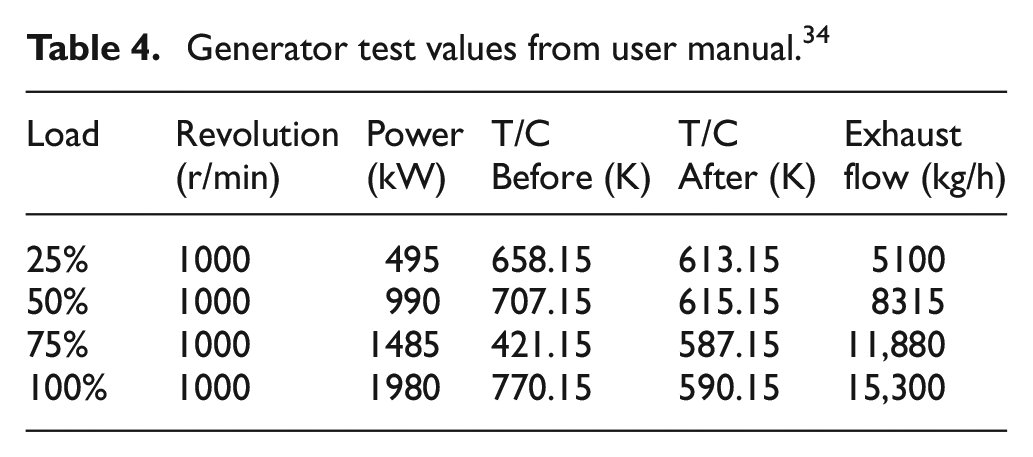
The analyses within the scope of the study were carried out for this lowest capacity situation. The generator remains at least 25% load while the ship is in port. The outlet temperature of the exhaust gas was accepted as 413.15 K based on the dew point to prevent acid formation and so cold corrosion due to the sulfur content of the fuel. 36 Thus, it was tried to determine that it can be used even with minimum recovery and how much fuel is saved both in the boiler and on the ship. Table 4 shows the test data of the generators on the ship taken from the MAN 9L21/31 diesel engine user manual.
Generator test values from user manual. 34
Performance criteria and exergy efficiency
In this section, energy analyses, exergy analyses, and fuel efficiencies of scenarios that use waste heat from the exhaust of diesel generators to preheat the main engines and to generate fresh water of an RO-RO vessel under port or anchorage conditions are analyzed based on PC and ε values for applicability point of view of the triple heat-exchanger.
WHR methods are steady flow open systems from a thermodynamic point of view. The continuity expression according to the law of conservation of mass, for all systems with material flow is shown in equation (1).
Furthermore, the equation of the law of conservation of energy for these systems is written as in equation (2);

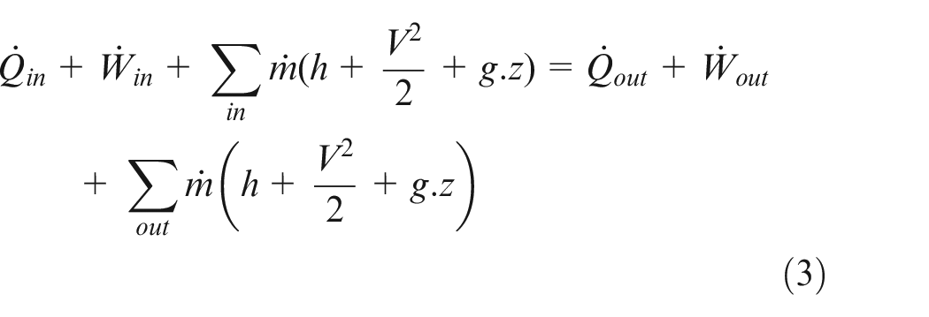
The energy balance of the first law of thermodynamics for continuously open systems with continuous flow is given in equation (3) including heat, work, physical, kinetic, and potential energies.
Heat transfer by convection from the surface of the main engine is shown in equation (4). Besides, the radiation heat dissipation from the main engine of the considered ship is neglected since it is about 10% less than the convection heat dissipation.

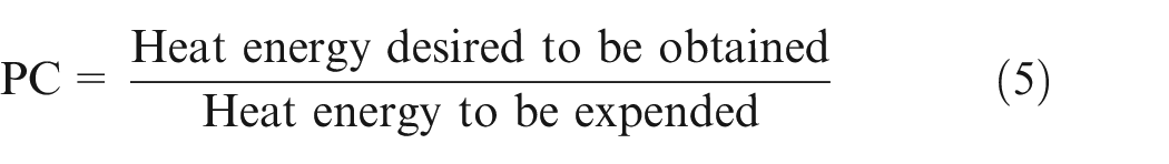
The general expression of the PC proposed in this study as a novel measurement term is defined by equation (5).
In open systems with continuous flow, the exergy flux for each point is calculated according to equation (6). The exergy of each point is calculated by equation (7).


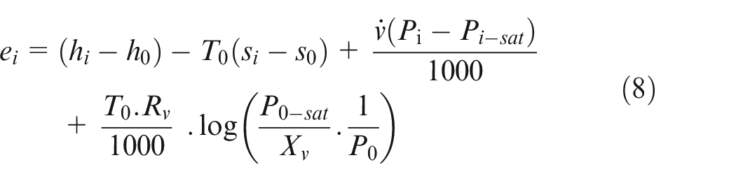
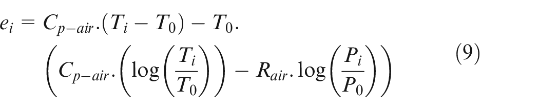
In the application of energy and exergy analyses for the scenarios included in the study, the definitions introduced in the literature by Bejan et al. 37 and Saraç 38 are used and presented below. In the thermodynamic model used in the study, the fluid inlet and outlet exergy fluxes of each component in the system for water and steam are calculated by equation (8), and the fluid inlet and outlet exergies for exhaust are calculated by equation (9). The total fluid exergy in the considered fluid streams is calculated by equation (7). In the exergy analysis, the thermodynamic conditions of the dead point for water were assumed as; pressure P0 = 101.25 kPa, temperature T0 = 288.15°K, relative humidity φ = 0.50, gas constant Rst = 0.4615kJ/kmol.K. For exhaust gas, the thermodynamic conditions of the dead point were assumed as, pressure P0 = 101.25 kPa, temperature T0 = 288.15°K, relative humidity φ = 0.50, gas constant Rair = 0.287 kJ/kmol.K, specific heat Cp-air=1.005 kJ/kg.K.
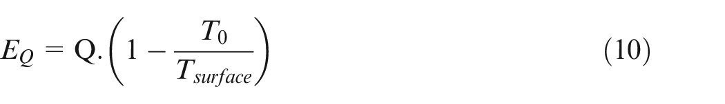
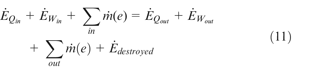
The exergy of work is equal to itself, and the exergy of heat was calculated by equations (10) and (11) is used for the exergy analysis of a continuous open system with continuous flow.
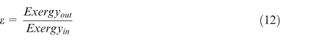
In the literature, there are different expressions related to exergy efficiency. Among these, the commonly used definition of exergy efficiency is the ratio of the exergy obtained to the exergy supplied proposed. 39 The exergy efficiency used in this study is calculated by equation (12).
Validation study
The thermodynamic calculation results of the theoretical model were compared with the calculated results of measured values by applying the same scenarios in both ports by the relevant ship personnel to prove the validity of the measurements and prepared code. The data of the study were obtained between October 1, 2021, and December 31, 2021, while the ship was performing its voyages to Pendik and Trieste ports. In this context, the mass flow rates of the exhaust gas required for the exhaust gas-water heat exchanger placed in the exhaust pipeline, the jacket cooling water and the amount of water steam required for heating the cooling water were calculated.
In the calculations, the water temperatures at the inlet and outlet of the heaters and the flow rate of the preheating pump are taken into consideration for the thermal energy of the jacket water. If the ship is in operation such as unloading or loading, the load of the generator increases as cargo fans, ballast pumps or hydraulic pumps are operated. However, apart from these issues, there is an average load of 450–500 kW on the generator.
Based on the test results read from the manual, the air consumption at 100% load is about 7.72 kg/kWh, which is equal to 15,300 kg/h exhaust flow rate for 1980 kW and has an exhaust gas T/C outlet temperature of 330°C. Accordingly, at 25% load of the generator, the air consumption is about 10.3 kg/kWh and the exhaust flow rate for 495 kW is equivalent to 5100 kg/h. Also from the table, the exhaust temperature at 25% load is found to be approximately 330°C. The exhaust waste heat load to be obtained by reducing the exhaust temperature to 140°C is calculated as 269 kW. The steam cycle and heaters used on board are shown in Figure 4. According to the real-time data taken from the ship, T1-T3 values are 78°C and T2-T4 values are 84 degrees when the main engine is in preheating. The water flow rate of the preheating pump is 16 m3/h.
Existing Steam system and preheaters in the ship. 32
The jacket water thermal energy load (heat duty) of a single main engine was found to be 111.5 kW. Since there are two main engines on board, the total thermal energy need is 223 kW. As a result of the calculations, it is seen that the minimum heat energy that can be provided from the exhaust gas is more than what is needed in the preheating process of the engines (
Since the pressure losses is very low, they are not taken into account. Isentropic efficiency η = 0.85 was taken for preheater in the calculations. The heat load requirement to be transferred to each main engine cooling water is calculated as 131.2 kW. At 6 bar operating pressure, the phase change enthalpy of steam was found from the table as 2085 kJ/kg. After calculations, the mass flow rate of steam (msteam) was obtained as 226.5 kg/h. The amount of steam heat load spent on one preheater on the fuel consumption in the boiler was found 11.19 kg/h. Since two preheaters are in operation, the total fuel consumption (mfuel) is calculated as 22.38 kg/h MGO. The msteam and mfuel values obtained above as a result of the theoretical calculation with the data taken from the operating manual were compared with the calculation results obtained with the data collected under ship operating conditions during port.
During the monitoring process, the flowmeter in the boiler fuel supply line was recorded at the beginning of each hour. The load-time diagram on the boiler control panel was recorded. The load variation of the boiler for the hours during which the scenario considered for the port of Triesta is realized is given in Figure 5. Fuel consumption per unit hour was measured in liters. In this context, the counter on the auxiliary boiler fuel supply line was noted for several consecutive hours. At the beginning of the second hour, the heater steam supply of one main engine was switched off. Thus, the steam consumption for one main engine was eliminated. However, since the heater of the other engine was activated, the steam consumption continued. Then, at the beginning of the third hour, the heater was switched on and the fuel consumption was continued to be monitored for each hour.
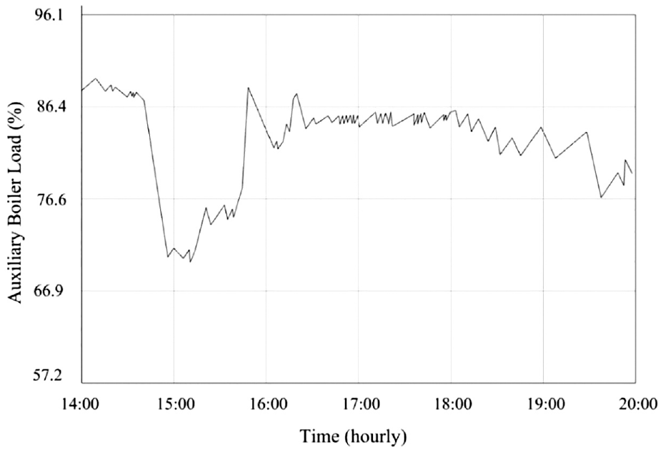
Variation of boiler load at Triesta port over time from the existing control unit of the ship. 32
As a result, if we accept the average hourly fuel consumption in the boiler as 145 l; 15 l fuel economy is achieved by saving steam consumption in only one heater. If both heaters are disabled, 30 l of fuel economy is achieved per hour. At an hourly expenditure for two heaters (fuel density for MGO: 827.9 kg/m3), the fuel saving is 24.8 kg/h.
The data provided by the boiler’s automation system. While the boiler load is around 82% on average, it decreases to around 70% when a jacket water heater is disabled. It is seen that there is a 12% reduction in the boiler load. Considering the boiler’s capacity 2000 kg/h for 100% load, it is assumed that the boiler capacity is 240 kg/h for 12% load change.
When the ship arrived at Pendik port, the second set of measurements were made during the port period. In the second trial, when only one main engine heater was deactivated, MGO fuel saving values of 17 l/h were determined. The value found by deactivating a single heater is assumed to be 34 l when two heaters are deactivated. The fuel savings for two heaters at an hourly expenditure was found to be 28.14 kg/h.
The load change of the vessel for the hours when the scenario considered for Pendik Port was realized is given in the graph in Figure 6. These graph values are also the data provided by the boiler’s automation system. While the boiler load is around 83% on average, it decreases to around 70% when a jacket water heater is disabled. It is seen that there is a 13% reduction in the boiler load. Considering the boiler’s capacity of 2000 kg/h for 100% load, it is assumed that the boiler capacity is 260 kg/h for 13% load change.
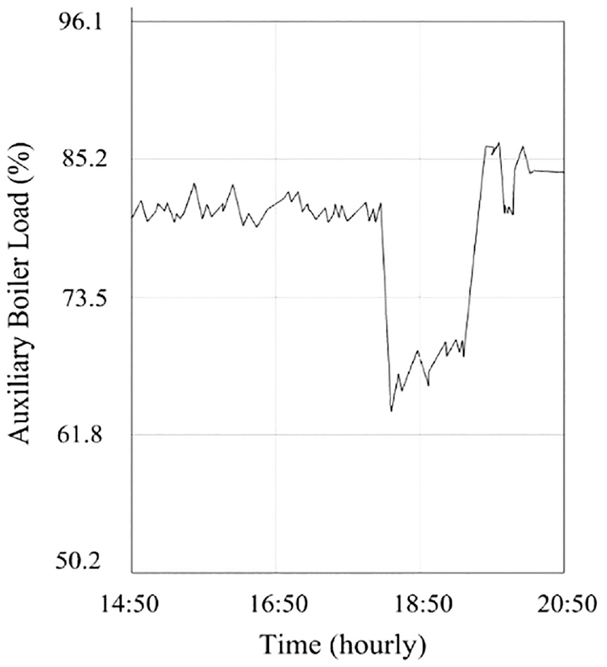
Variation of boiler load at Pendik port over time from the existing control unit of the ship. 32
According to the average values of the data obtained in the two ports, it was seen that there was an average steam requirement of 250 kg/h from only one heater. The total steam requirement from the two heaters is considered as 500 kg/h. In addition, when the two heaters were disabled together, the average of the two trials was accepted as 26.5 kg/h in MGO utilization. Under these assumptions, as a result of the voyages, the ship spends 24 h of port period per week and 1248 hof port period on average annually and it is calculated that annual fuel saving is 33 tons. Obtained results of hourly steam usage and fuel consumptions calculated with user manual data and port measurement data with similarity ratios are given in the Table 5.
Obtained results of hourly steam usage and fuel consumption. 33
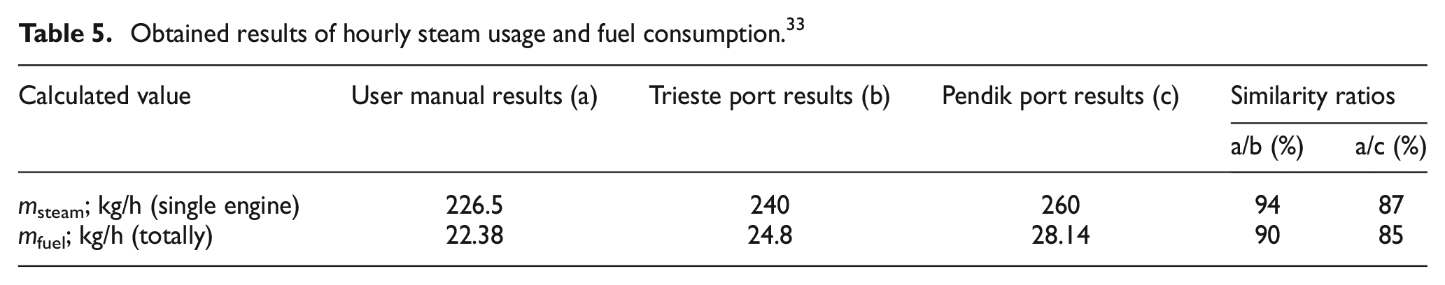
These values were determined with relative error rates of 0.05 for msteam and 0.09 for mfuel considering the results in Trieste port, and 0.12 for msteam and 0.20 for mfuel considering the results in Pendik port. As a result, using energy and mass equations based on real time data from the ship, steam and fuel mass flow rates were calculated under the assumptions mentioned above. These results were compared with the values of steam and fuel mass flow rates calculated with data taken from both the user manuals of the main and auxiliary engines and the real-time measuring. Compatible results were obtained.
Results and discussions
Exergy and energy assessment on voyage
This scenario represents the exergy and energy analysis of the cooling water (jacket water) system of the main engine while the ship is on voyage. The main engine cooling water system is a closed system and fresh water is used as the cooling fluid. In addition, the control volume under this study is thermodynamically an open system with continuous flow due to the mass inflow and outflow. The cooling system consists of the main engine, freshwater generator, jacket water cooler, and jacket water circulation pumps. This calculation was mainly conducted to determine the availability potentials of the energy used in the entire system cycle and for its components of the ship. It is aimed to prepare a reference for the case study scenarios proposed for the port by determining the PC and ε values of the control volume of the main engine cooling water cycle and the control volumes of the FWG cycle and jacket water cooling cycle, which are the sub-cycles of this main cycle. In addition, it is also aimed to be a reference for the new cycle of the proposed method including triple heat-exchanger. Figure 7 shows the main engine cooling water systems of the vessel used in the study.
All system, FWG and cooler control volumes of voyage state for reference scenario.
When the cycle is analyzed considering constant conditions, jacket water (1) exits from the main engine at 361.15 K and 95 m3/h flow rate. The main engine jacket water outlet temperature is the reference value and must be kept constant at 361.15 K. Thermodynamic properties of the quantities at the cycle points used in Scenario 1 is given in Table 6. In Table 6, the temperature (T), pressure (P), and mass flow rate (
Thermodynamic properties of the quantities at the cycle points.
The PC according to the first law of thermodynamics and the ε according to the second law of thermodynamics for the FEG, jacket water cooler, and all system are calculated with equations (13)–(18), respectively.
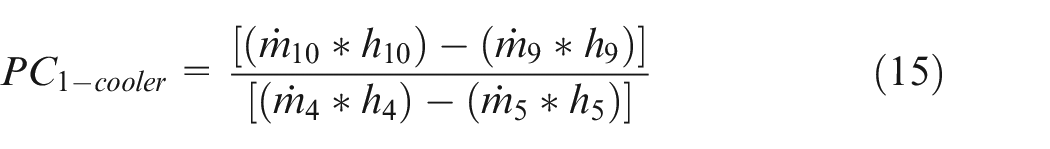
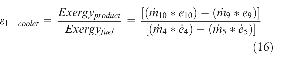
With the findings in Table 6, the PC and ε were calculated from the energy and exergy analysis of the freshwater generator, cooler, and the entire system on the cooling water system. The results obtained are given in Table 7.
Calculated PC and ε values for Scenario 1.
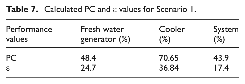
These results show that the low value of the exergy efficiency of the cooler is due to the small exergy of the water entering the cooler. Also, the destroyed exergy is high in the FWG also causes the second law efficiency to be low here. Accordingly, the fact that not all the exergy of the water in the jacket water inlet is used in the FWG causes the system efficiency to be low. In the light of these values, it can be said that the exergy efficiency of the system can be increased by further improving the operating conditions and preventing heat loss to the outside.
Case study with suggested method
For the operating conditions of different scenarios of the ship’s existing systems, evaluations were made with real-time data taken from the ship. Four different scenarios were created with these data and energy and exergy analyzes were applied and results were compared.
Scenario 1 – Ship is at port with existing pre-heating system
In Scenario 1, the preheating of the engine is considered when the ship is in port and the main engine is not running. Before the main engine is started, it is heated with jacket water (cooling water) from the cooling system with a heat exchanger. Thus, preheating of the cooling system and the main engine is ensured. The circulation and heating of the jacket water is provided by the preheating pump and heat exchanger located parallel to the jacket water pumps. The fluid that gives heat in the heat exchanger is water steam in the current practice. In this scenario, energy, and exergy analyses of the preheating system of the main engine have been applied also depending on different temperature conditions of the engine room. System and double heat exchanger control volumes of Scenario 1 for main engine pre-heating cycle at port period is given in Figure 8.
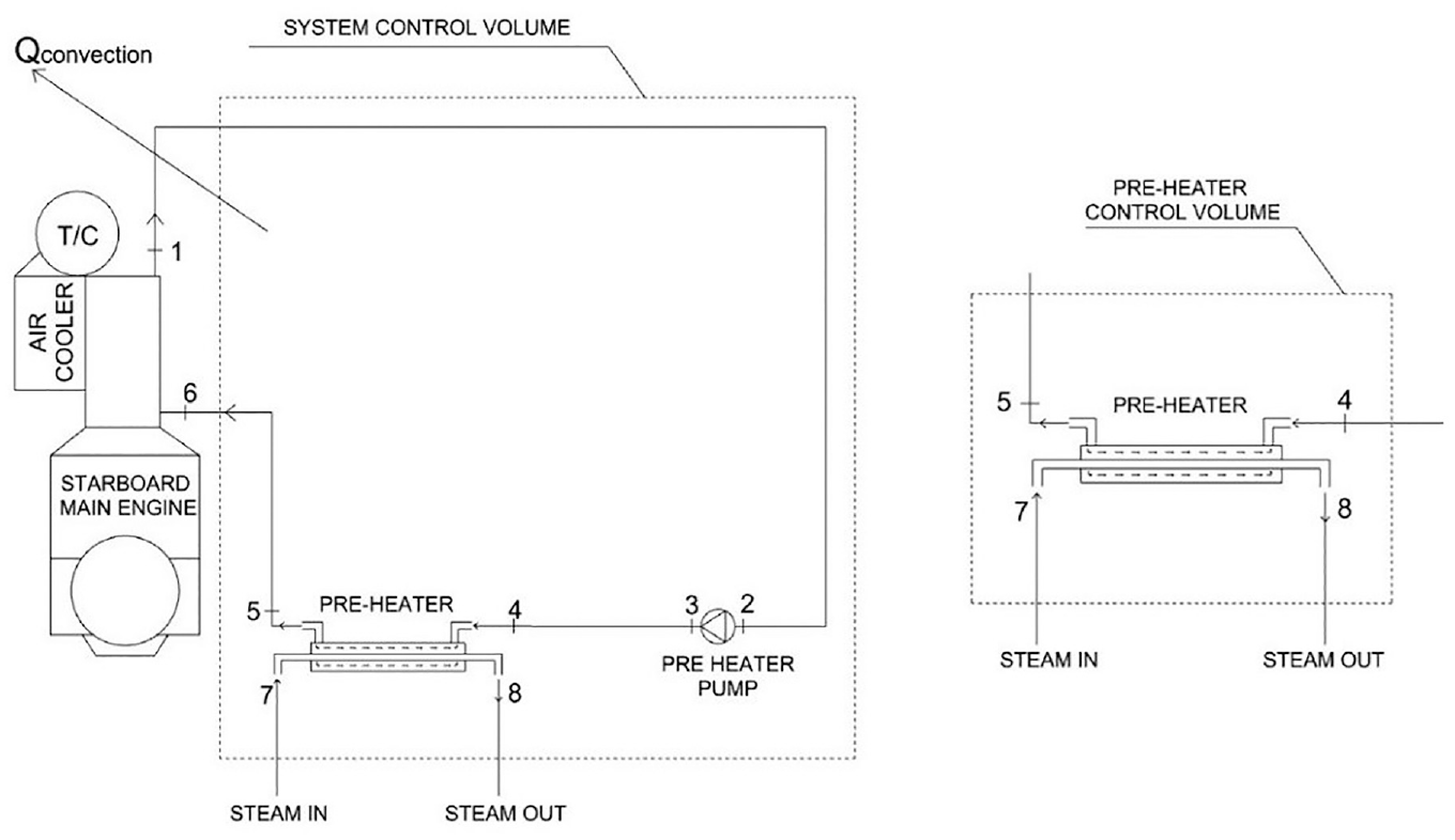
System and double heat exchanger control volumes of Scenario 1 for main engine pre-heating.
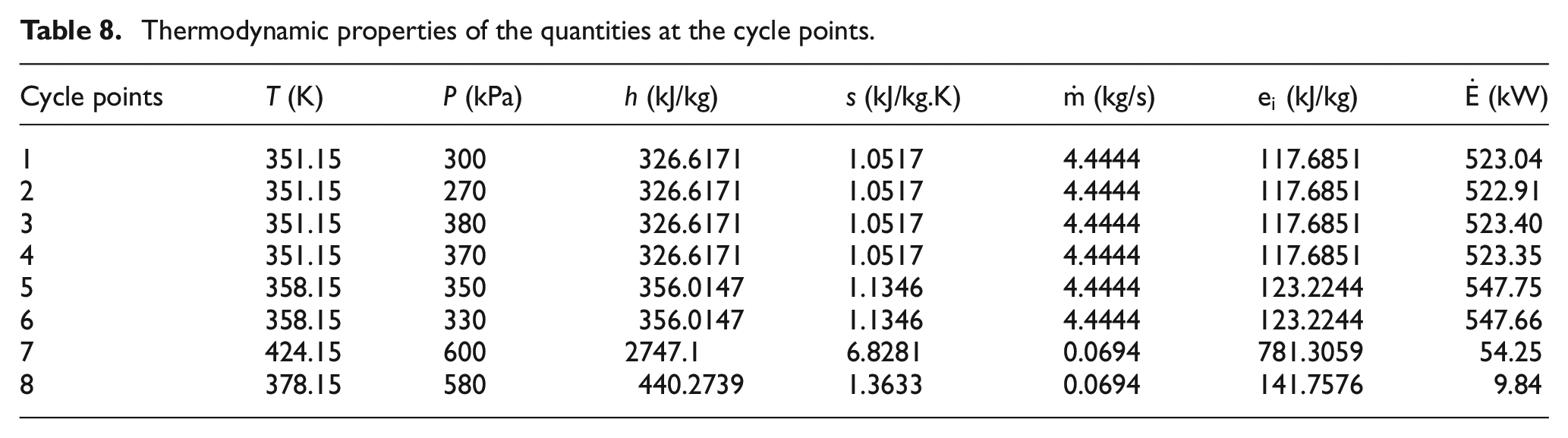
In the equation of heat transfer by convection from the surface of the main engine, the heat transfer coefficient k = 3, Asurface = 110 m2, Tsurface = 333.15 K are assumed. The ambient temperature of the engine room is assumed to vary between 283.15 K and 318.15 K due to weather conditions. Thermodynamic properties of the quantities at the cycle points used in Scenario 2 is given in Table 8.
Thermodynamic properties of the quantities at the cycle points.
The PC and ε values of the preheater and all system were calculated by equations (19)–(22), respectively.
With the findings in Table 8, the PC and ε of the heat exchanger on the main engine preheating system and the whole system were calculated. It was shown in Figure 9 that the PC and ε values of the system decrease as the ambient temperature increases. The heat exergy calculated using equation (10) includes equation (4), where the convection heat loss due to ambient temperature is calculated. Accordingly, as the ambient temperature increases, convection heat loss will decrease.
Variation of the system’s performance criterion and exergy efficiency with ambient temperature of the scenario 1.
This decreases the heat exergy calculated by equation 10. As a result, the calculated exergy efficiencies for the overall control volume and other sub-control volumes also decrease as the ambient temperature increases. It is observed that there is a 7% decrease in the PC and a 5% decrease in the ε. For the heat exchanger, the PC value was found 81.5% and ε value was found 54.9%.
Scenario 2 – Ship is at port with proposed double heat-exchanger
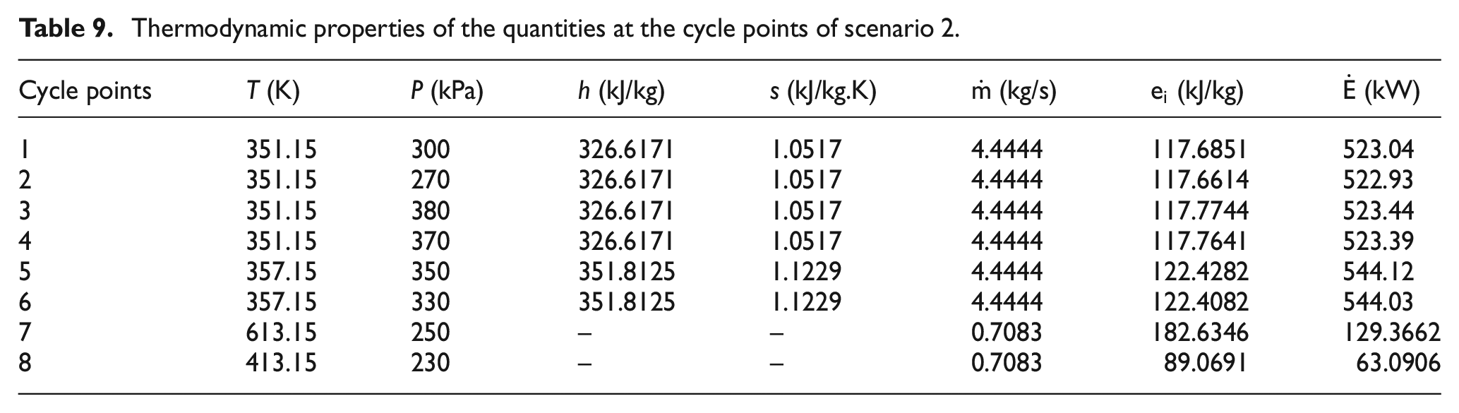
This scenario is similar to scenario 1, but unlike scenario 1, the diesel engine exhaust gas is used instead of steam in the heat exchanger cycle. The exhaust gas is supplied by diesel generators that meet the electricity needs of the ship. Energy and exergy analysis of the preheating system of the main engine has been carried out depending on the different temperature conditions of the engine room. Thermodynamic properties of the quantities at the cycle points used in Scenario 2 is given in Table 9.
Thermodynamic properties of the quantities at the cycle points of scenario 2.
For the preheater and all system, the PC and ε values were calculated by equations (23)–(26), respectively. PC and ε values are calculated separately for each 278.15 K increase of the ambient temperature (Tambient).
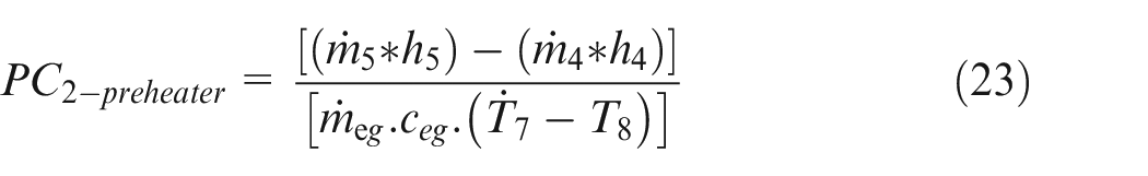
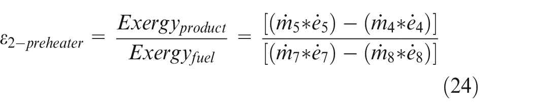
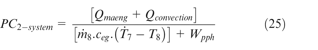
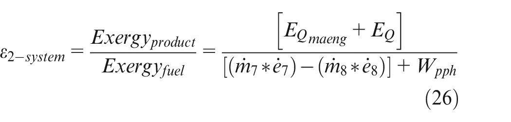
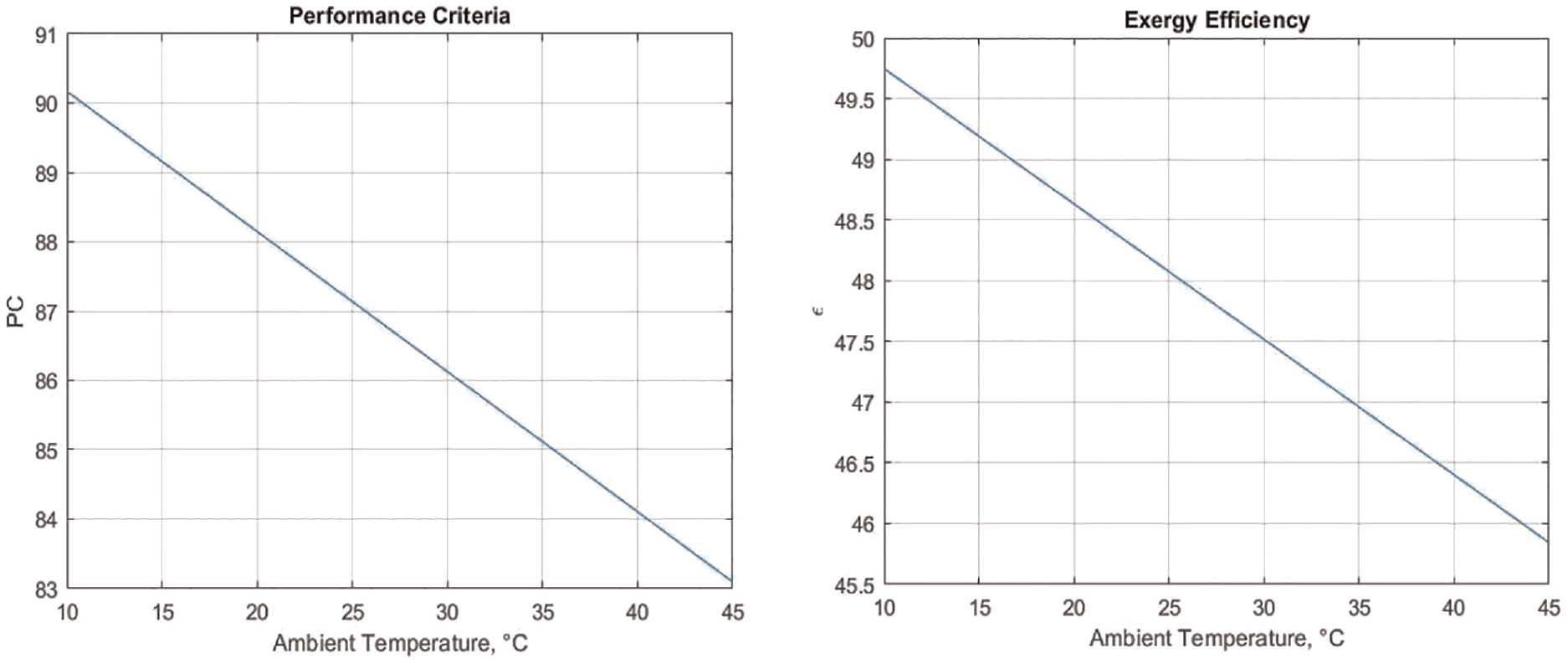
With the findings in Table 9, PC and ε were calculated for the heat exchanger on the main engine preheating system and also for the whole system. The PC value for the heat exchanger was found 78.6% and ε value was found 31.2%. It was shown in Figure 10 that the PC and ε values of the system in scenario 3 decrease as the ambient temperature increases. It is observed that there is an 8,5% decrease in the performance criterion and a 2,5% decrease in the exergy efficiency.
Variation of the system’s performance criterion and exergy efficiency with ambient temperature of the scenario 2.
Scenario 3 – Ship is at port with proposed one triple heat-exchanger for each engines
The heat energy on the exhaust we have is only sufficient to heat the main engines. The heat energy needed to provide water production in the FWG is met by steam. Therefore, it is necessary to add one more double heat exchanger (steam-jacket water) on the cycle to transfer the heat energy with steam to the jacket water when the main machine is stopped. As a result, there will be two double heat exchangers on the jacket water cycle, (exhaust-water), and (steam-water). However, since convection heat losses and installation costs will increase due to a new heat exchanger and piping to be added, a single triple heat exchanger is proposed.
In this scenario, both the preheating system of the main engine and the freshwater generation are investigated at the same time, when the ship is in port and the main engine is not running. A triple heat exchanger is proposed as a pre-heater for each single main engine. The first fluid is main engine jacket water, the second fluid is generator exhaust gas, and the third fluid is water steam. The diagram of cycle for scenario 3 is shown in Figure 11.
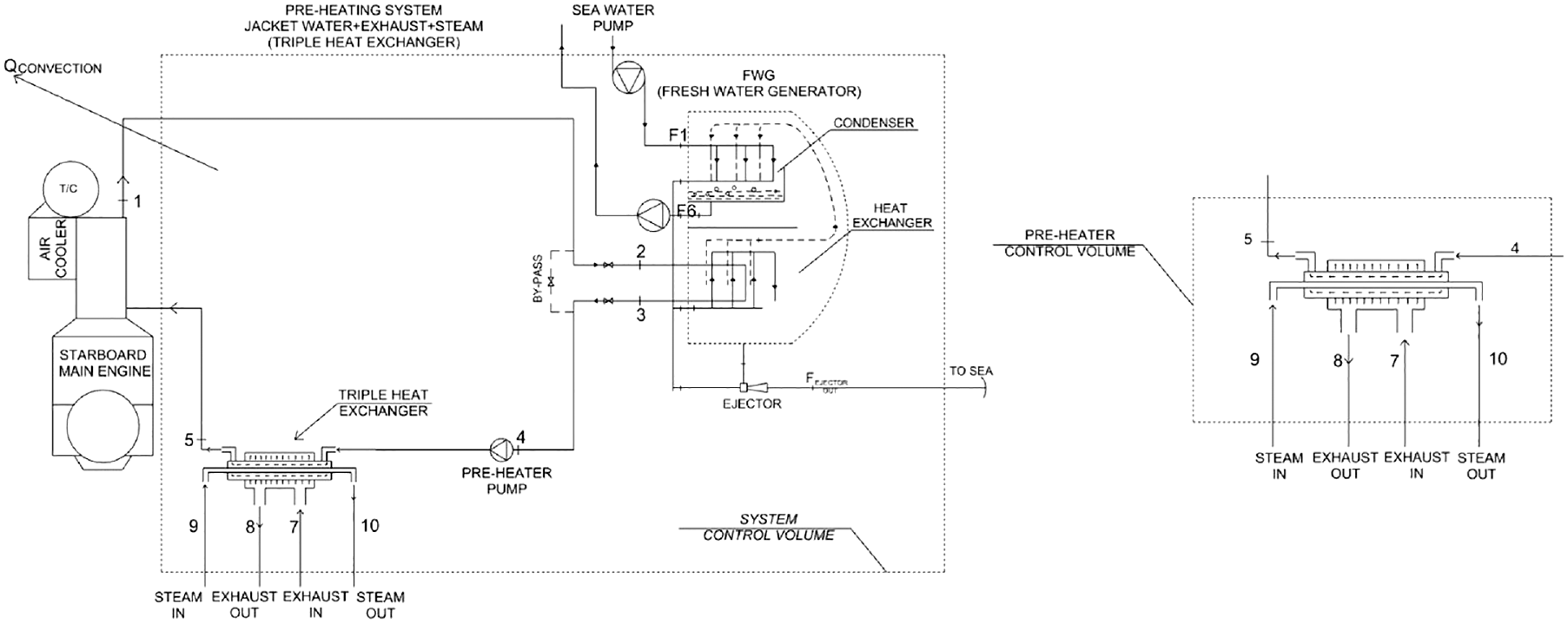
System and triple heat exchanger control volumes of Scenario 3 for single main engine.
With the proposed new heat exchanger, it is aimed to utilize the waste heat in the generator exhaust and heat the jacket water to heat the main machine and to produce fresh water with the evaporator. However, since it was foreseen that the heat from the generator exhaust would not be sufficient, water vapor was preferred as the third heat source in the heat exchanger.
In the triple heat exchanger, jacket water enters at piping connection (4) and exits at piping connection (5). The generator exhaust enters the heat exchanger through piping connection (7) and leaves the heat exchanger through circuit connection (8). Thus, heat energy input is provided to the jacket water and the preheating operation of the main engine is carried out. Here, the heat energy on the jacket water at the outlet of the main engine is utilized in the freshwater generator (2 and 3). However, more heat energy input is required in the heat exchanger to meet the heat energy requirement of the main engine and freshwater generator. For this reason, the heat energy carried by a third fluid, steam, is utilized in the heat exchanger. The steam enters the heat exchanger at connection (9) and exits at connection (10).
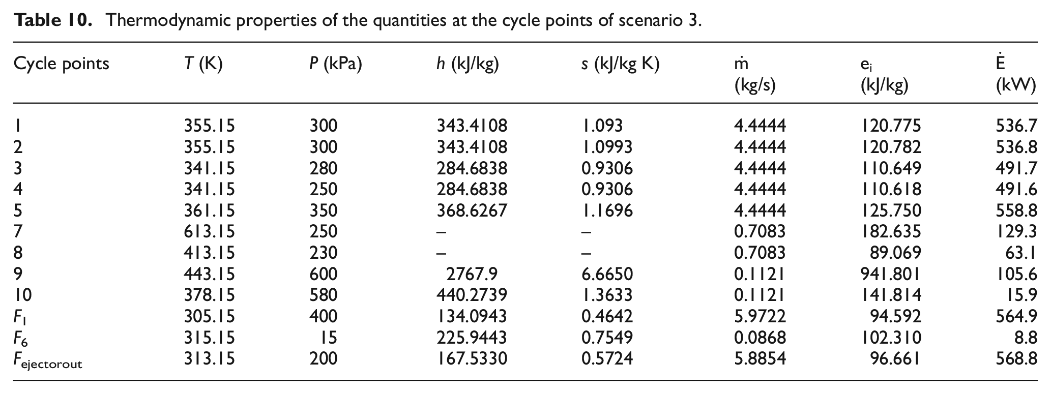
Energy and exergy analyses of the preheating system of the main engine have been carried out depending on different ambient temperatures of the engine room. Thermodynamic properties of the quantities at the cycle points used in Scenario 3 is given in Table 10.
Thermodynamic properties of the quantities at the cycle points of scenario 3.
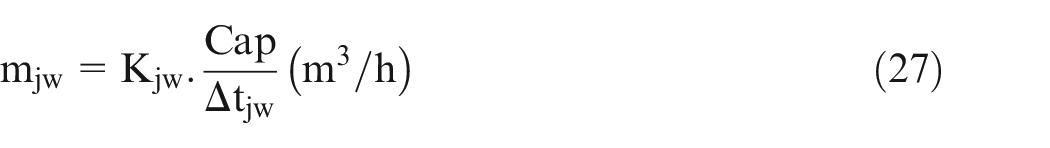
Since the flow capacity of the preheating pump is lower than the main jacket water circulation pumps, the heat energy at the inlet of the FWG will also be low. FWG water production capacity according to the jacket water flow rate is calculated by equation (27).
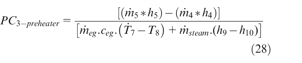
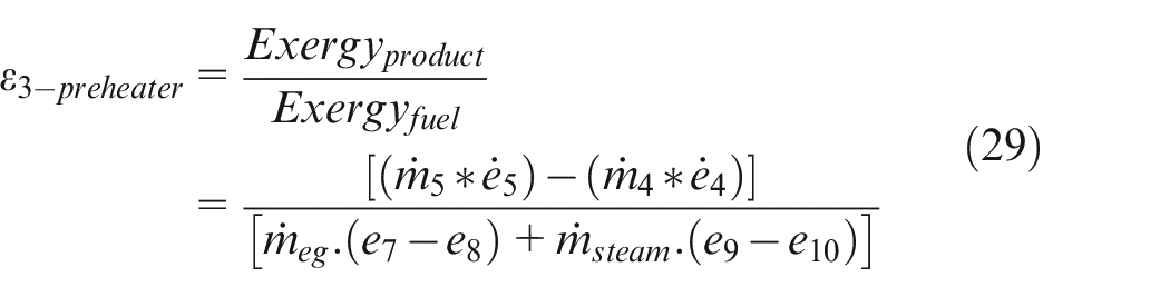
Performance criterion (PC) according to the first law of thermodynamics and second law exergy efficiency (ε) calculations for the pre-heater were calculated by equations (28) and (29), respectively.
Here, half of the exhaust gas mass (meg) is taken, and the remaining part of the mass is considered for heating the other main engine. The amount of steam mass is considered depending on the heat demand in the FWG and was calculated by equation (30).

Performance criterion (PC) according to the first law of thermodynamics and second law exergy efficiency (ε) calculations for all system cycle were calculated by equations (31) and (32), respectively.
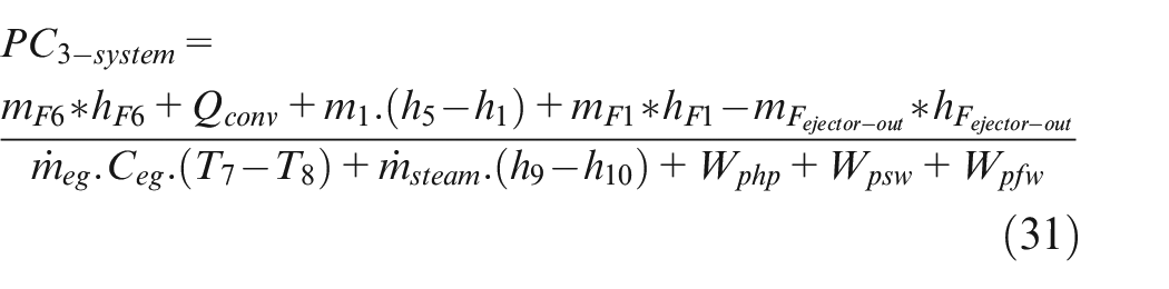
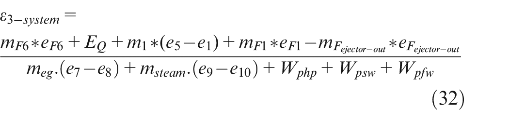
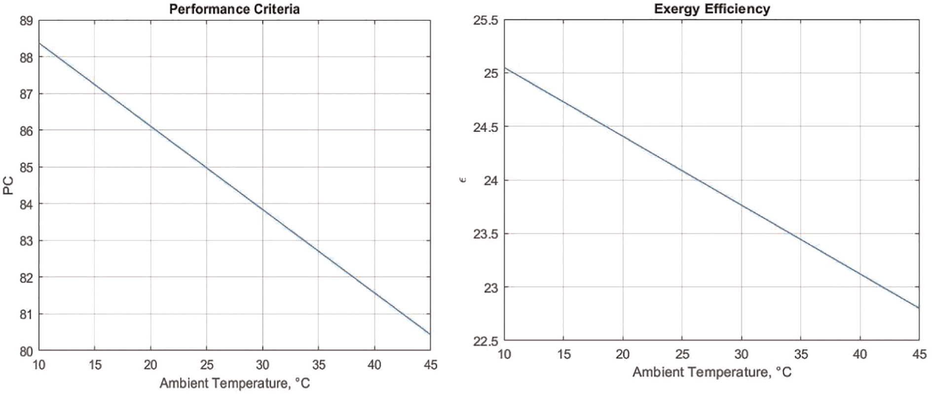
With the findings in Table 10, PC and ε were calculated for the heat exchanger on the main engine preheating system and also for the whole system. The PC value for the heat exchanger was found 92.4% and ε value was found 43.1%. Besides, this has been found that, each 1 kW heat energy reduction on steam will provide 0.0853 kg/h fuel saving in the boiler. Thus, 273 kg CO2 emission will be reduced for each kw of heat energy to be obtained. It was shown in Figure 12 that the PC and ε values of the system in scenario 3 decrease as the ambient temperature increases. It is observed that there is an 2.5% decrease in the performance criterion and a 1% decrease in the exergy efficiency.
Variation of the system’s performance criterion and exergy efficiency with ambient temperature of the scenario 3.
Scenario 4 – Ship is at port with proposed one triple heat-exchanger for two engines
In this scenario, again both the preheating system of the main engine and the freshwater generation are investigated at the same time when the ship is in port and the main engine is not running. There are two main engines on board and each of them has an own cooling water cycle. Here, it is aimed to preheat the machines with a single triple heat exchanger without mixing the two cooling waters. The advantages mentioned for triple heat exchanger in scenario 3 are also considered for scenario 4 and water-exhaust-water heat exchanger is considered, and a single triple heat exchanger is proposed for two main engines for heating the engine jacket water by utilizing the waste heat in the generator exhaust gas. The diagram of cycle for scenario 4 is shown in Figure 13.
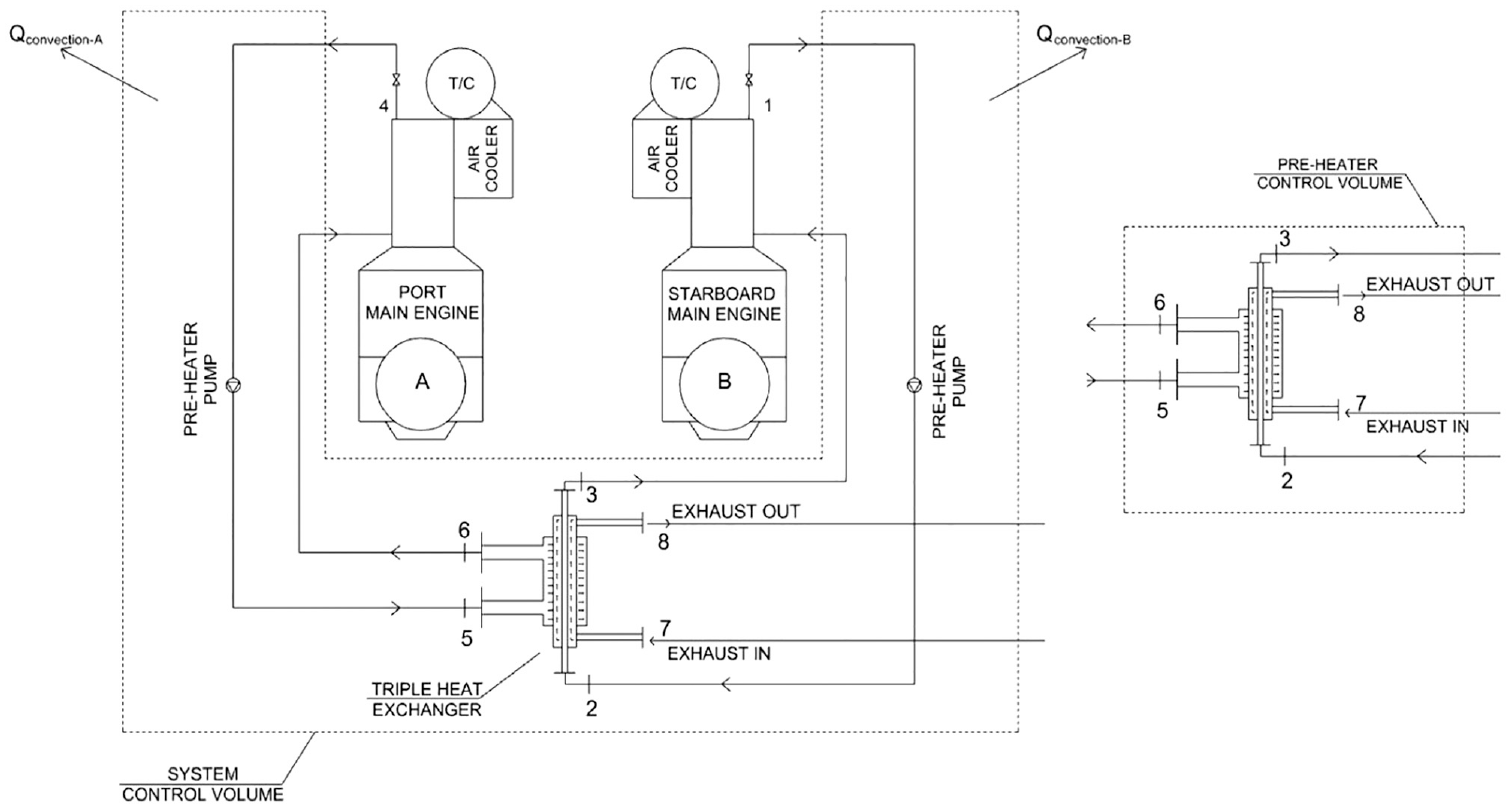
System and triple heat exchanger control volumes of scenario 4 for two main engines.
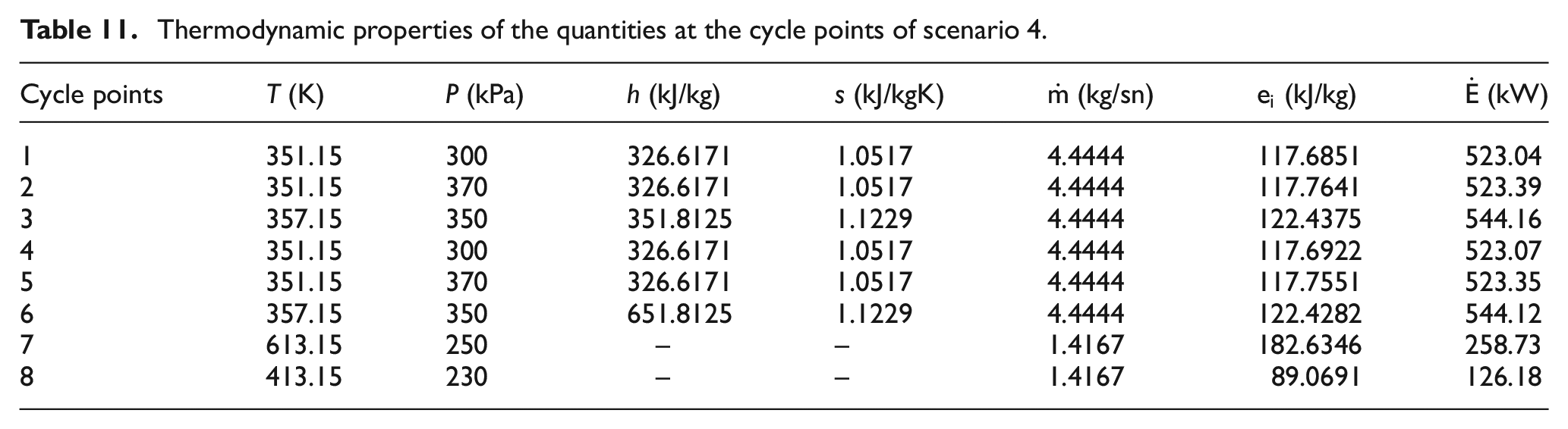
A triple heat exchanger is proposed as a common pre-heater for two main engines. The first fluid is main engine jacket water, the second fluid is generator exhaust gas, and the third fluid is jacket water. The main purpose here is to ensure that the two jacket waters circulating for two different main engines are not mixed. Otherwise, the qualities of the waters (PH, hardness, conductivity, etc.), which may be different from each other, may adversely affect each other. In addition, when the jacket water of one main engine needs to be cut off (maintenance, etc.), it will be possible to ensure that the other engine can continue its operation. Therefore, it would be more feasible to heat two different main machine jacket waters from one heat source with a single heat exchanger. Energy and exergy analyses of the pre-heating system of the main engines have been carried out depending on different temperature conditions of the engine room. Thermodynamic properties of the quantities at the cycle points used in Scenario 4 is given in Table 11.
Thermodynamic properties of the quantities at the cycle points of scenario 4.
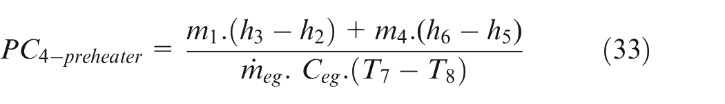
Performance criterion (PC) according to the first law of thermodynamics and second law exergy efficiency (ε) calculations for the pre-heater were calculated by equations (33) and (34), respectively.
Performance criterion (PC) according to the first law of thermodynamics and second law exergy efficiency (ε) calculations for all system cycle were calculated by equations (35) and (36), respectively.
The total heat load of the main machines is given by equation (37). Total exergies are denoted by EQ.

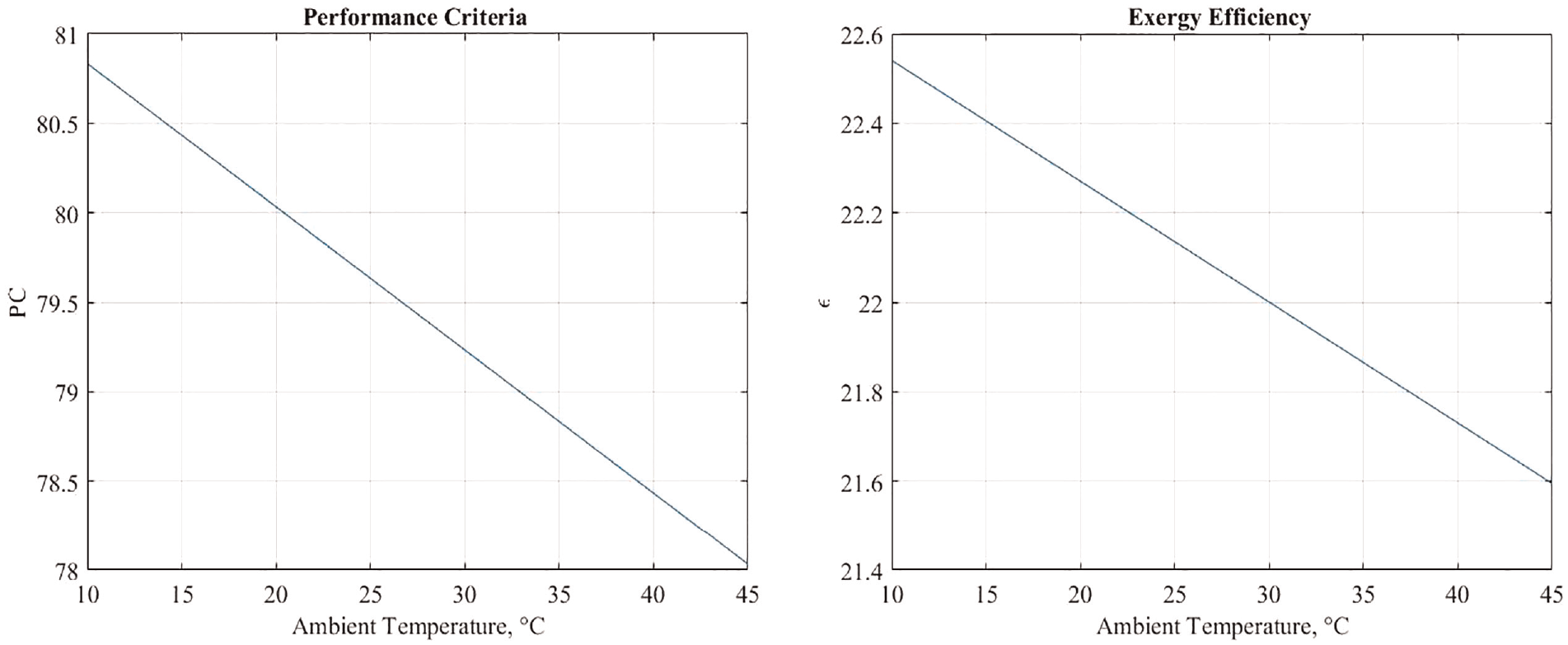
With the data in Table 10, PC and ε were calculated for the heat exchanger on the main engine preheating system and also for the whole system. The PC value for the heat exchanger was found 77.02% and ε value was found 29.98%. It was shown in Figure 14 that the PC and ε values of the system in scenario 3 decrease as the ambient temperature increases. It is observed that there is an 2.5% decrease in the performance criterion and a 1% decrease in the exergy efficiency. and ε value was found 29.98%. It was shown in Figure 14 that the PC and ε values of the system in scenario 3 decrease as the ambient temperature increases. It is observed that there is an 2.5% decrease in the performance criterion and a 1% decrease in the exergy efficiency.
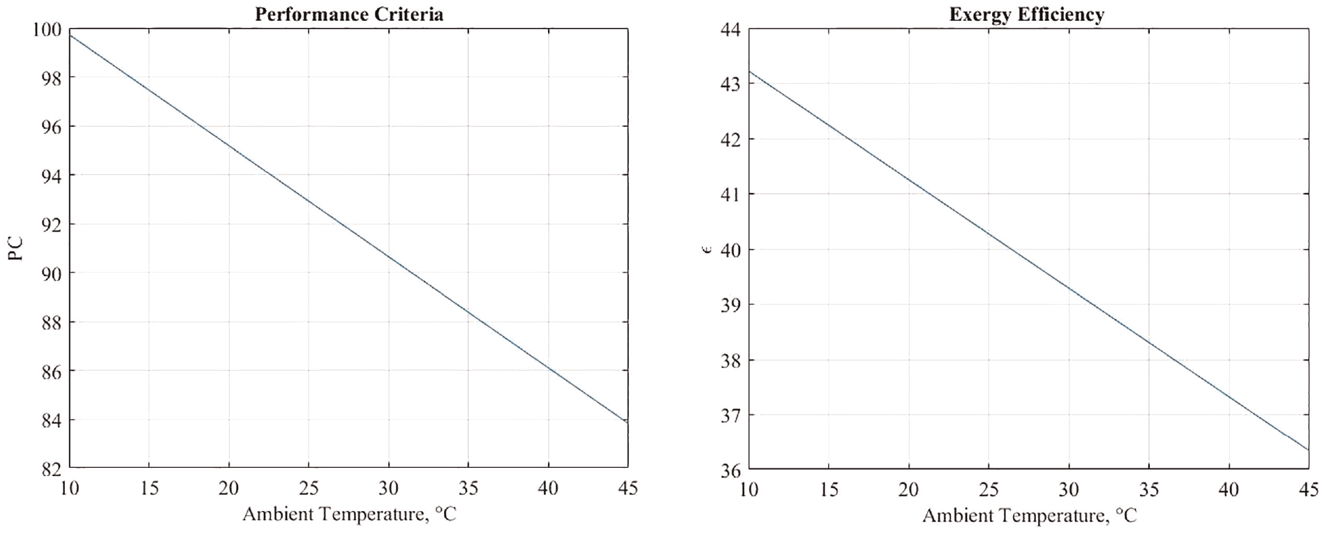
Variation of the system’s performance criterion and exergy efficiency with ambient temperature of the scenario 4.
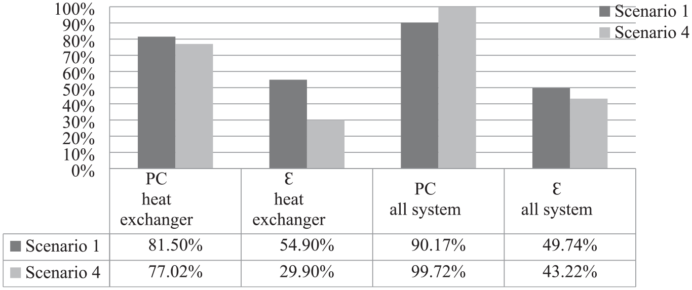
The thermodynamic analysis results of the existing cycle system for main engine preheater and the total system proposed in this study are given in Figure 15. The performance criteria and the exergy efficiency values of the heat exchanger in the proposed system was obtained 3.1% and 23.7% lower, respectively.
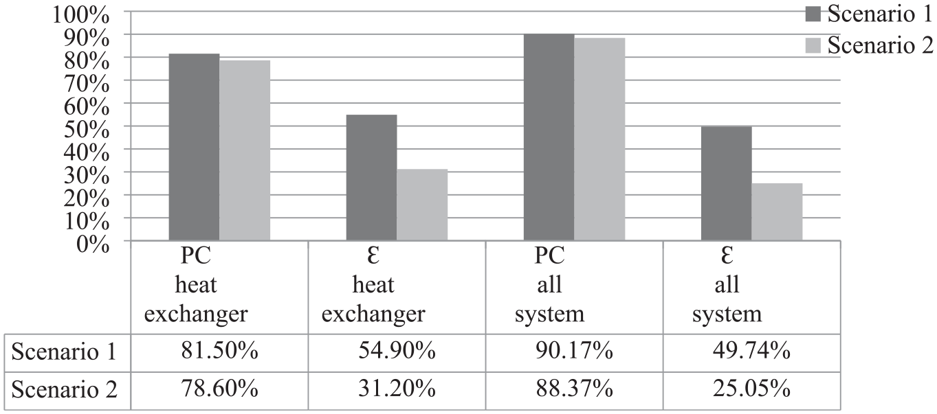
Comparative results for scenario 1 and scenario 2 at 283.15 K ambient temperature.
The results of the change in performance criteria and the exergy efficiency values obtained for the range of 10 –45 with 5 increments of ambient temperature are also given in Table 12. It can be emphasized that, the PC and ε values of the system decrease as the ambient temperature increases. Accordingly, it is determined that the new model double heat exchanger has a feasible potential, but also needs to be improved.
PC and ε values change for the range of ambient temperature for scenarios 1 and 2.
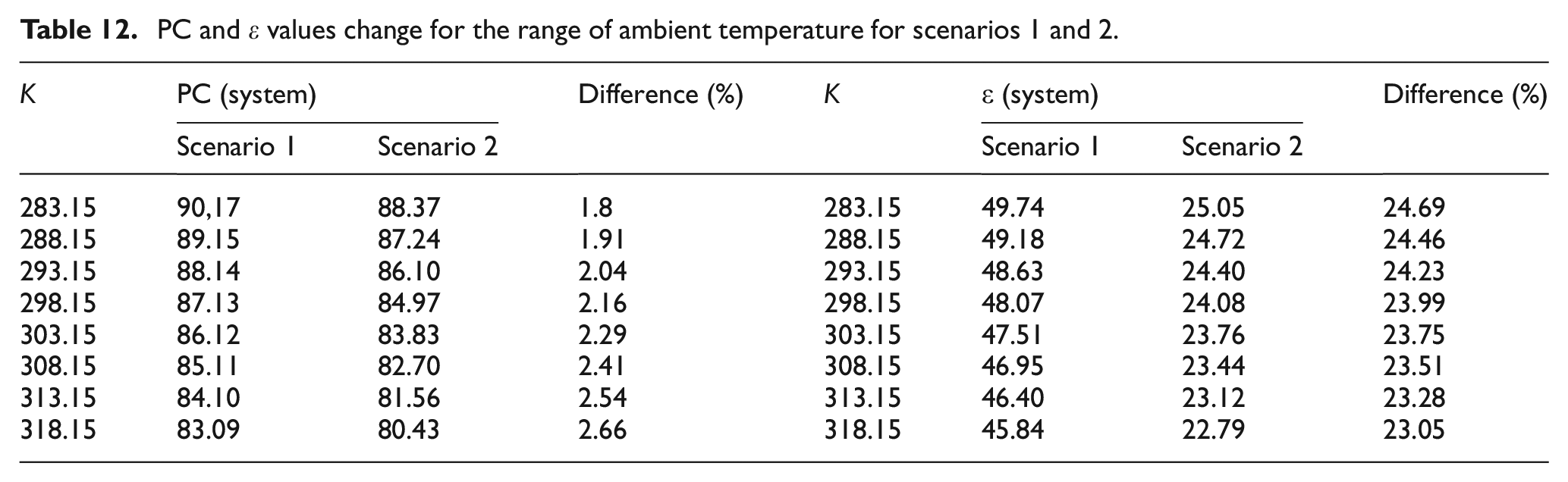
Figure 16 compares the performance criteria and exergy efficiencies of the double heat exchanger proposed in scenario 1 and the triple heat exchanger proposed in scenario 3. It is concluded that the performance criteria are close in both scenarios, but the exergy efficiencies are lower for scenario 3. Therefore, it is seen that the applicability of the proposed new model is high, and this model should be further developed.
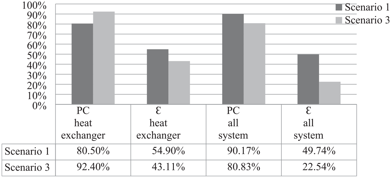
Comparative results for scenarios 1 and 3 at 283.15 K ambient temperature.
System PK and ε findings at other temperature values of the machine room are given in Table 13.
PC and ε values change for the range of ambient temperature for scenarios 1 and 3.
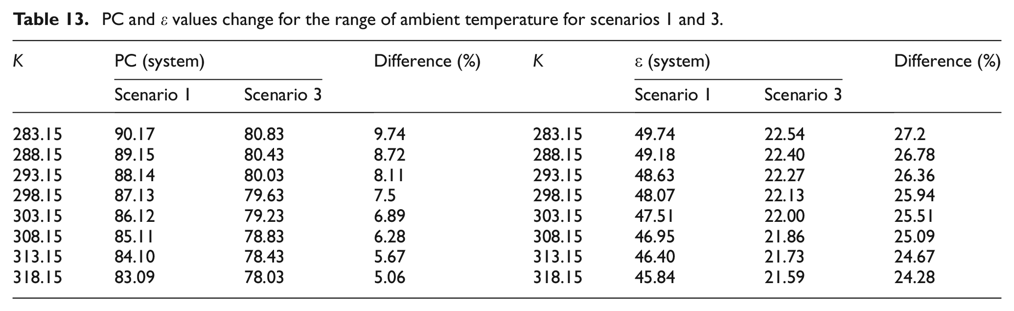
Figure 17 compares the performance criteria and exergy efficiencies of the double heat exchanger proposed in scenario 1 and the triple heat exchanger proposed in scenario 4. The performance criteria are close in both scenarios, but the exergy efficiencies are lower for scenario 4. Therefore, it is seen that the applicability of the proposed new model is high, and this model should be further developed.
Comparative results for scenario 1 and scenario 4 at 283.15 K ambient temperature.
System PK and ε findings at other temperature values of the machine room are given in Table 14.
PC and ε values change for the range of ambient temperature for scenarios 1 and 4.
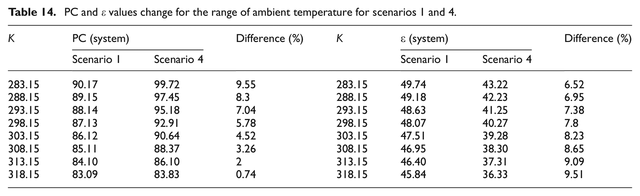
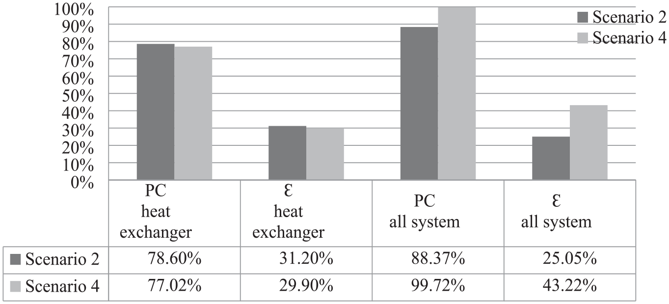
Figure 18 compares the performance criteria and exergy efficiencies of the double heat exchanger proposed in scenario 2 and the triple heat exchanger proposed in scenario 3. It is concluded that the performance criteria and exergy efficiency values of the heat exchanger have increased in scenario 3. Besides, these values have been determined quite similar for whole system cycles.
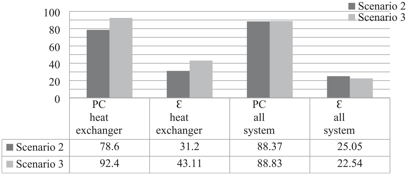
Comparative results for scenarios 2 and 3 at 283.15 K ambient temperature.
System PK and ε findings at other temperature values of the machine room are given in Table 15.
PC and ε values change for the range of ambient temperature for scenarios 2 and 3.
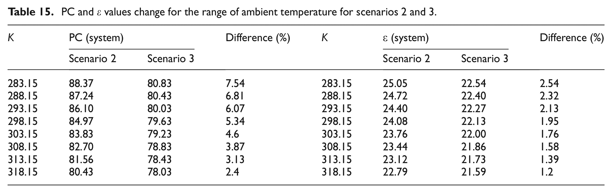
Figure 19 compares the performance criteria and exergy efficiencies of the double heat exchanger proposed in scenario 2 and the triple heat exchanger proposed in scenario 4. It is concluded that the performance criteria and exergy efficiency values of all system cycle have increased in scenario 4. Besides, these values have been determined quite similar for heat exchangers.
Comparative results for scenario 2 and scenario 4 at 283.15 K ambient temperature.
System PK and ε findings at other temperature values of the machine room are given in Table 16.
PC and ε values change for the range of ambient temperature for scenarios 2 and 4.
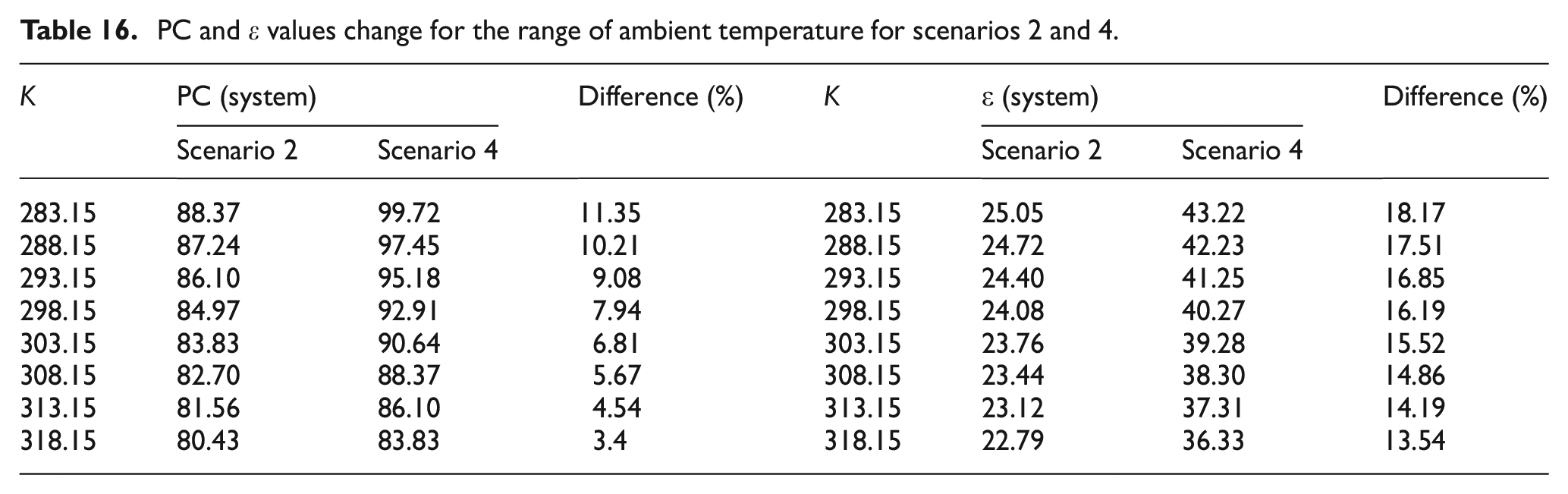
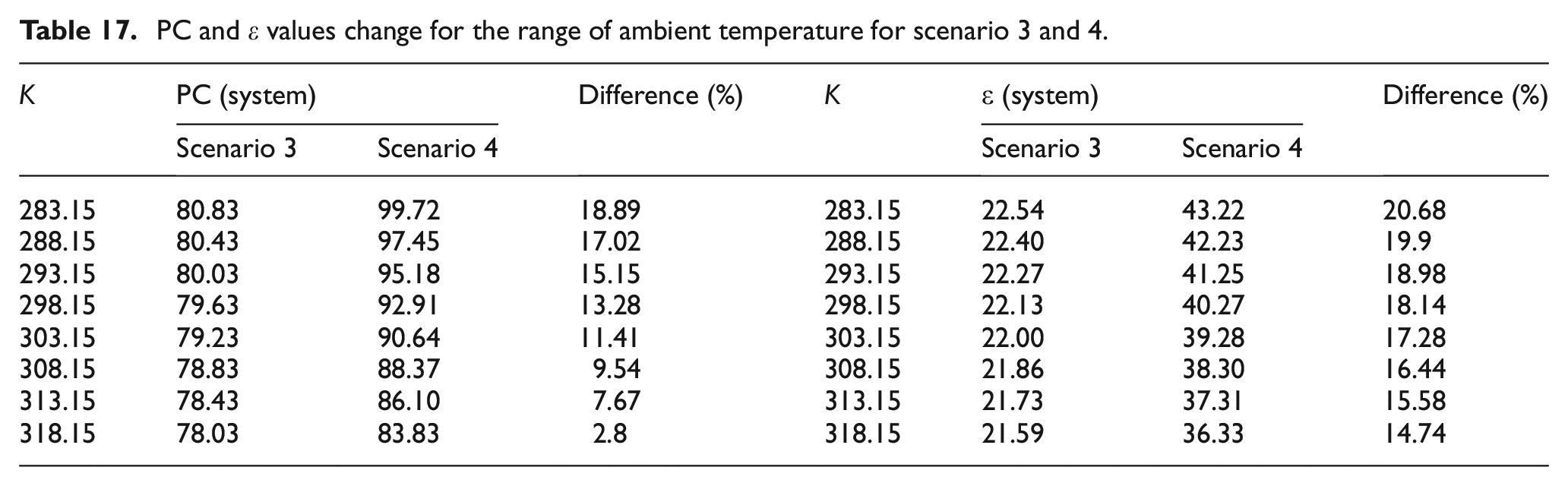
Figure 20 shows the results of the performance criteria and exergy efficiencies obtained with the roles of the triple heat exchangers in different scenarios. In scenario 3, the performance criteria and exergy efficiency values of the triple heat exchanger with jacket water-exhaust-steam fluids are higher than the performance criteria and exergy efficiency values of the triple heat exchanger with jacket water-exhaust-jacket water fluids in scenario 4. However, the performance criteria and exergy efficiencies calculated for the whole system are higher in scenario 4.
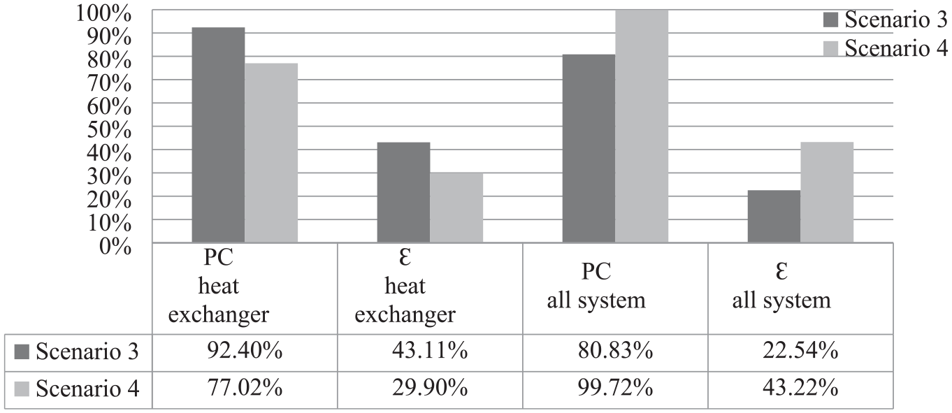
Comparative results for scenarios 3 and 4 at 283.15 K ambient temperature.
System PK and ε findings at other temperature values of the machine room are given in Table 17.
PC and ε values change for the range of ambient temperature for scenario 3 and 4.
Conclusions
In this study, it is aimed to determine the possible energy savings to be achieved in preheating operations to keep the main engine of the ship at temperatures close to the operating conditions when the main engine is not operated. Current preheating operations are provided by steam heat energy obtained with some fuel consumption in the boiler. With the method proposed within the scope of the study, it is aimed to meet the heat energy needed in the preheating process from the energy in the exhaust of the diesel generator that is currently running continuously. Besides, it is also proposed in this study that if the triple heat-exchanger is applicable and sufficient or not for main engine pre-heating and freshwater generation systems at the same time during port operations. It is studied for both one pre-heater for each main engine and for one common pre-heater for two main engines.
With the new method with double and triple heat exchangers presented in the scope of the study, fuel saving is achieved in the main engine preheating and this amount is calculated with the heat energy on the exhaust that will occur at 25% load of the generator. This heat energy is only sufficient for the preheating process of the main engines. However, in different operation scenarios of the ship such as ballast, loading and unloading, the load on the generator will increase, and therefore the heat energy on the exhaust will increase. Thus, this increase will reduce the required steam heat energy and reduce the fuel consumption for water generation.
The theoretical calculations of the system with real-time data measured from the ship under study and the theoretical calculations of the system have been examined by thermodynamic analysis and it has been shown that the exhaust heat energy of the diesel generator will be sufficient for the preheating process of the main engine even at the lowest working load. From the point of view of irreversibility, considering control volumes which the thermodynamic analyses were carried out for the port condition, the heat exchanger where the main modification in the system was applied was also identified as the component with the lowest exergy efficiency and the one that needs the most improvement.
As a conclusion, when the positive numerical results obtained above are evaluated, 22% fuel savings were achieved from the expenditure in the boiler by measured and calculated data and 8% fuel savings for the whole ship during the port periods according to the daily consumption data taken from chief engineer of the ship.
According to the average values of the data obtained in the two ports, it was seen that there was an average steam requirement of 250 kg/h from only one heater. The total steam requirement from the two heaters is considered as 500 kg/h. In addition, when the two heaters were disabled together, it was calculated that 26.5 kg/h MGO fuel saving was achieved in the boiler by utilizing the waste heat energy on the exhaust of the generator in the process of preheating the two main engines on board. Since the actual measurement value cannot be used due to the lack of an onboard application in the current situation, the MGO fuel consumption in the boiler for steam production of 0.1121 kg/h (403.5 kg/h), which is the value in Table 9, is estimated to be approximately 33 kg/h based on the calculations made within the scope of Scenario 3 with reference to the values measured above.
This heat on the exhaust is sufficient for only two main engines. While the main engines are in the preheating process, approximately 261 kW of heat energy is required to operate the FWG on the jacket water cycle. This energy required for water production creates approximately 22.27 kg fuel consumption in the boiler. However, the increase in the generator load in different operations of the ship (loading-unloading, ballast operations, etc.) will increase the waste heat energy on the exhaust. Therefore, the need for heat energy to be supplied from steam in the triple heat exchanger will decrease. Each 1 kW heat energy reduction on steam will provide 0.0853 kg/h fuel saving in the boiler. Thus, 273 kg CO2 emission will be reduced for each kw of heat energy to be obtained. Obtaining more detailed analysis and results on emissions and parameters that may affect emissions is of course possible and would be a useful study. However, within the scope of this study, since the main purpose of this study is to determine the applicability, possible fuel consumption and approximate CO2 emission reduction potential, and again due to the page limitation of the journal, this detailed emission study for different generator loads is planned as the purpose of the next study subject. In this context, an approximate CO2 emission reduction value based on the obtained feasibility and fuel consumption indicators is presented.
In conclusion, the use of triple heat exchangers for pre-heating marine engines and generating fresh water on board ships has the potential to improve energy efficiency and reduce emissions. However, careful consideration must be given to the design, operation, and maintenance of the system in order to maximize its benefits and minimize potential challenges.
Footnotes
Appendix
Acknowledgements
We thank Prof. Teoman AYHAN for assistance with performance criteria and exergy efficiency assessments and for comments that greatly improved the manuscript and encourage us to apply triple heat-exchanger on ship main engine pre-heating and FWG systems during port conditions.
Authors contribution
Köksal Çolak: Methodology, developing computer codes, writing – original draft. Hasan Ölmez: Conceptualization, drawings, review & editing computer codes, writing – review & editing. Betül Saraç: Conceptualization, editing computer codes.
Declaration of conflicting interests
The author(s) declared no potential conflicts of interest with respect to the research, authorship, and/or publication of this article.
Funding
The author(s) received no financial support for the research, authorship, and/or publication of this article.