
Abstract
Global aquaculture is in exponential trend to fulfil the demand for seafood due to the rise in world population. Most countries have implemented nearshore farming and reached their limits, which impacts water quality parameters. Offshore farming is the alternative option to counteract this nearshore farming issue and balance the aquaculture demand and supply. The present study construes on the numerical study of the porous wall fencing offshore fish cage subjected to regular waves. The numerical analysis is carried out for four cages by varying porous hole diameters from 0.5 to 0.7 m and without porosity. All the cages are placed at the same water depth of 200 m, interacting with a constant wave height of 6m with wave periods ranging from 6.92 to 19.05 s. Both frequency and time domain analysis are conducted to study the variation of hydrodynamic parameters, namely added mass, wave excitation forces, radiational potential damping, motion responses, and mooring line tension. Among all cage configurations, the cage with 0.5 m diameter porous hole fencing performs better for all wave conditions considered. Also, a scaled model of 1:75 was considered in both experimental and numerical studies for the purpose of validation. It is learnt that experimental parameters such as motion responses and mooring line tension are in good agreement.
Introduction
Traditional cage farming has been practiced for hundreds of years, initially in freshwater and later in seawater. Modern cage technologies, however, have only been developed in the past 20 to 30 years, particularly in tandem with the booming of the salmon farming sector. The cages were first made using wood, bamboo, polystyrene, poles buoys and were intended to be placed in protected areas on nearshore seas. Later, steel and High-Density Polyethylene (HDPE) materials were used for framing the fish cages. Numerous design concepts have evolved and been tested over the past 10–15 years. An offshore cage development has roughly followed the footsteps of nearshore cage development, albeit it has only just reached the stage of conceptual. The cage designs are developed by devoted research teams, established cage producers, net producers, naval architects, shipbuilders, and producers of oil drilling hose.1,2 Further, there is a need of hour to shape out the design of offshore cages, which will increase cultivation, control fish populations and reduce the initial capital cost.
At the inception of offshore farming, High Density Polyethylene (HDPE) material was used as a cage frame. HDPE cages can withstand a moderate sea environment and are durable, relatively economical and easy to install. The major drawbacks of these flexible cages were deformation, twisting and turning when the cage interacts with strong waves and currents.3,4 To counteract these problems with flexible cages, rigid cage designs have emerged with a large internal volume, which can withstand severe sea environments instead of compliant against wave actions. The rigid cage has leverage that can withstand strong waves and currents. It can offer a balanced working platform to facilitate the maintenance and repair of the required feeding and harvesting entities. However, the detriments of the rigid cages involve a structural failure in severe storm conditions, requiring superior port facilities, and relatively high cost for towing, maintenance, and repair. 5 To reduce the susceptibility to structural failure, the cages were submerged below sea water level during storm conditions. In recent times, closed containment tank designs have evolved to prevent the fish from sealices and parasites. Closed containment tanks have a sophisticated design that can maintain the water supply and its removal, temperature, and sufficient oxygen. Limited research is visible on the design of offshore farming which is evident from the review papers4–8 and studies on offshore agriculture are scarce.
An experimental and numerical analysis was conducted by Jurado et al. 9 on a floating cylindrical structure to study the motion responses in free-floating and moored conditions. The cage was subjected to regular and irregular waves combined with currents. A unique system of ordinary differential equations was developed to validate the physical tests. Forces on the net, drift forces, and sloshing effect inside the cage were not considered for the analysis. All the experimental and numerical results were in reasonable agreement with all the environmental conditions considered. Later, a novel multipurpose project was developed as part of “The Blue Growth Farm.” The multipurpose projects include aquaculture cages, wind and wave energy converters. A sophisticated numerical algorithm was developed by Li et al. 10 to study the motion responses, modal analysis, rigid body, and coupled body analysis in realistic environmental conditions. A set of numerical methods and finite element methods were used. Li et al. 10 studied the performance of various shapes of the fish cages and explored the optimum shape of the multipurpose platform and the results from this study might be helpful for similar kinds of projects which may be tried in the near future.
Chu and Wang 11 designed an innovative fish cage design with an octagon cage Combined with a SPAR platform (COSPAR). A preliminary study was conducted using commercial software such as ANSYS AQWA, WAMIT, FAST, and SIMA. In the first phase, the performance of the cage alone was analyzed. Later, the study was extended to analyze the cage integrated with a spar. The motion responses, mooring line tension, and other hydrodynamic properties namely added mass, wave excitation forces, radiation potential damping, were analyzed for site-specific conditions. The cage with a spar platform showed better motion responses in all environmental conditions because of its larger mass. Continuing the above study, COSPAR with partial porous wave fencing (circular holes) configuration was considered. 12 The cage was octagon-shaped with cylindrical porous wave fencing on the top. A hydrodynamic analysis was carried out on non-porous wave fencing due to limitations in modeling for porous fencing in ANSYS AQWA software.
Further, Chu and Wang 13 explored the performance of an octagon cage with cylindrical fencing on top of it. The parameters such as transmission, reflection, and energy loss coefficient of the COSPAR cage were studied using the BEM approach. Four configurations of cages such as (i) Single, (ii) Double net, (iii) Single net with collar barrier, and (iv) Double net with collar barrier, were studied under different submergence conditions of 2–8 m. The porosity of the collar barrier was considered in a range of 0.25–0.75. The results conclude that the cage exhibited better performance for a submergence depth of 4 m and with a porosity of 0.25 for the double collar barrier. Even though the above combination exhibits better performance, the double collar barriers with a porosity combination of 0.25 for first plate and 0.5 for second plate was recommended for COSPAR to save a collar material by 25%.
Using a computational fluid dynamics approach, Martin et al. 14 developed a complete numerical framework for Open Ocean Aquaculture (OOA). Studies were conducted on rigid nets, flexible nets, pontoons with and without nets, Oceanfarm1, and Havfarm2. In order to study the motion responses and deformation of the net, a structural dynamics model was developed using a lumped mass method, nonlinear material law, and implicit time step advancing approaches. Floating objects with mooring lines and fluid-structure interactions with fixed conditions are studied using a novel floating algorithm based on the continuous direct force immersed boundary method. There was good agreement with the results of existing works.
To investigate the nonlinear vertical accelerations and mooring line tensions under severe wave-current situations, Yu et al. 15 carried out experimental and analytical investigations on a scaled model. The findings of the assessment of first- and second-order harmonic accelerations at five distinct places revealed that both accelerations were independent of position. For wave heights greater than 0.2 m, the percentage of difference between the experimental and numerical results is higher in the wave-only circumstances. A comparable percentage of difference was also found for the wave-current mixed conditions. The second-order vertical accelerations were accelerated more when a fishing net was present, and the mooring tensions increased with the speed of the current. Later, Miao et al. 16 developed a hybrid numerical model in both direct and indirect time domain approaches to study the motion responses and validate them with physical tests. Since the semi-submersible offshore structure is huge, a 3D potential theory was used to analyze pontoons’ heave and pitch motions. Similarly, the Morison equation and screen model were used for the frame system and net. Wave heights, draughts, and net solidity ratio were shown to be the main influencing factors in structure motion responses. According to data from experiments and numerical simulations, the hydrodynamic parameters were closely matched. Cage draughts significantly influenced motion responses, then by net solidity and wave heights.
A numerical investigation was carried out on a semi-submersible steel frame cage in regular waves using a computational fluid dynamic approach using REEF 3D. 17 Using the screen force model, the motion responses of the offshore cage were investigated. A sophisticated mooring system can control the heave and pitch motion responses, and the surge motion was wave-sensitive. Similar to this, there was a positive correlation between the horizontal and vertical loadings and the wave heights and periods. Motion responses showed a negligible effect due to presence of net, whereas the opposite was true for horizontal forces. Further, Gharechae and Abazari 18 developed an analytical method to study cage floater’s motion responses and power output capacity of cage integrated with point absorbers. The elastic motion of the floater was modeled based on slender body theories and matched asymptotic expansions. The elastic motion coupled with dynamic equations of Point Absorber Wave Energy Converts (PAWEC) were used to study the power output. Three different numbers of 4, 6, and 8 PAWECs were considered, with sphere radius ranging from 0.5 to 1.5 m. The results showed the cage configuration with six PAWECs and a sphere radius of 0.75–1 m obtained a maximum power output.
From the literature, it is learnt that limited works on porous wave fencing are available. Further, the experimental work is scanty and its necessity is understood for the validation purpose. The topic of research work is the need of the hour for a better understanding of design of floating cages which will be extended as a grid system. The present study describes the square cage with porous wall wave fencing with a porosity of 0.144–0.15. Four different cases are considered by varying the porous hole diameter from 0.5 to 0.7 m with a porosity of 0.144–0.15. Motion responses and mooring line tensions are analyzed for each cage. A series of laboratory and numerical tests are conducted on a scaled model of 1:75 to validate the ANSYS AQWA results.
Experimental and numerical setup of scaled model
Model studies play a crucial role in coastal engineering problems since direct interactions between waves and structures can be understood. Physical models can represent a physical system in different scales. 19 Establishing similitude requirements and choosing a model scale before the start of any physical model investigations is essential. A comparison between a prototype and a model can be made when factors influencing the physical phenomenon are proportional. According to Hughes, 19 model similitude can be established using calibration, differential equations, dimensional analysis, and scale series.
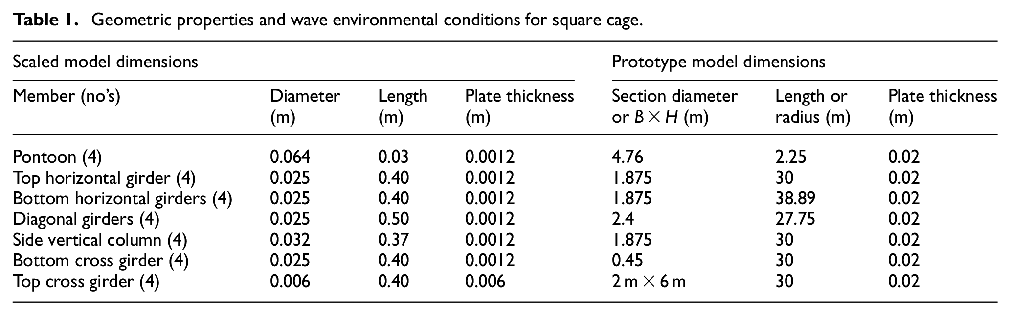
Froude similarity scale of 1:75 is used for geometric, kinematic, and dynamic similarity. The laboratory model tests are conducted in wave flume laboratory at Department of Water Resources and Ocean Engineering, National Institute of Technology Karnataka, India. Two-dimensional wave flume has length of 50 m, width of 0.71 m, and depth of 1.1 m (Figure 1). A bottom hinged flap wave generator can generate a series of regular waves with distinct wave periods and wave heights. The geometric properties of the scaled model square cage are provided in Table 1 for experimental and numerical works. The cage is designed with hollow circular steel members, which helps to maintain buoyancy. The cage consists of four vertical columns, diagonal girders, radial girders, top and bottom horizontal girders, and four pontoons. A High-Density Polyethylene (HDPE) knotted net with a diamond mesh was used for the present study, and the net solidity was about 0.26.
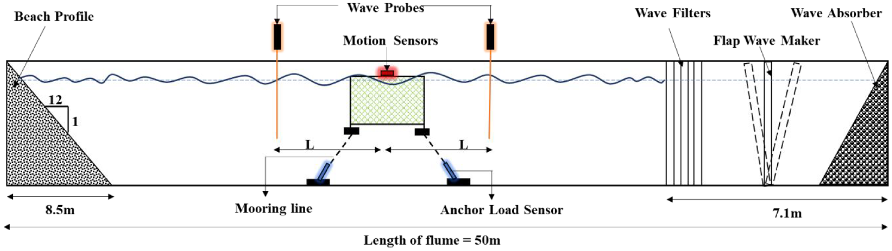
Schematic diagram of two-dimensional wave flume.
Geometric properties and wave environmental conditions for square cage.
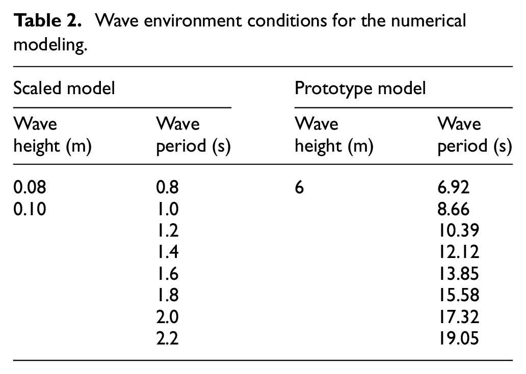
In the present experimental study, hydrodynamic responses of heave and pitch motions are measured using the heave and tilt sensors, respectively by fixing them in the middle portion of the structure. The anchor line tension is measured using underwater load cells, which have a capacity of 7.35 N. Each test is conducted three times to check the repetitive nature of experimental data. A detailed schematic diagram is provided in Figure 1 for a better understanding of the cage arrangement in flume. The water depth in the flume is maintained as 55 cm and the mode was exposed to wave heights of 8 and 10 cm. The wave periods of 0.8–2.2 s with an interval of 0.2 s were considered. The wave conditions are reproduced in the numerical modeling (Table 2).
Wave environment conditions for the numerical modeling.
The arrangement of a cage in flume and simulation of the model in ANSYS AQWA is provided in Figure 2.
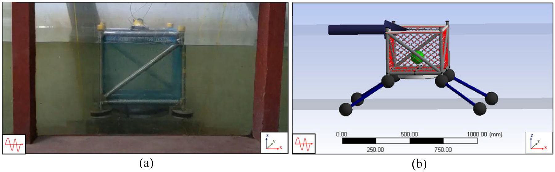
The model of a square cage in (a) experimental work and (b) simulation in ANSYS AQWA.
Methodology of numerical work
A brief methodology used for the present numerical work is provided in Figure 3.
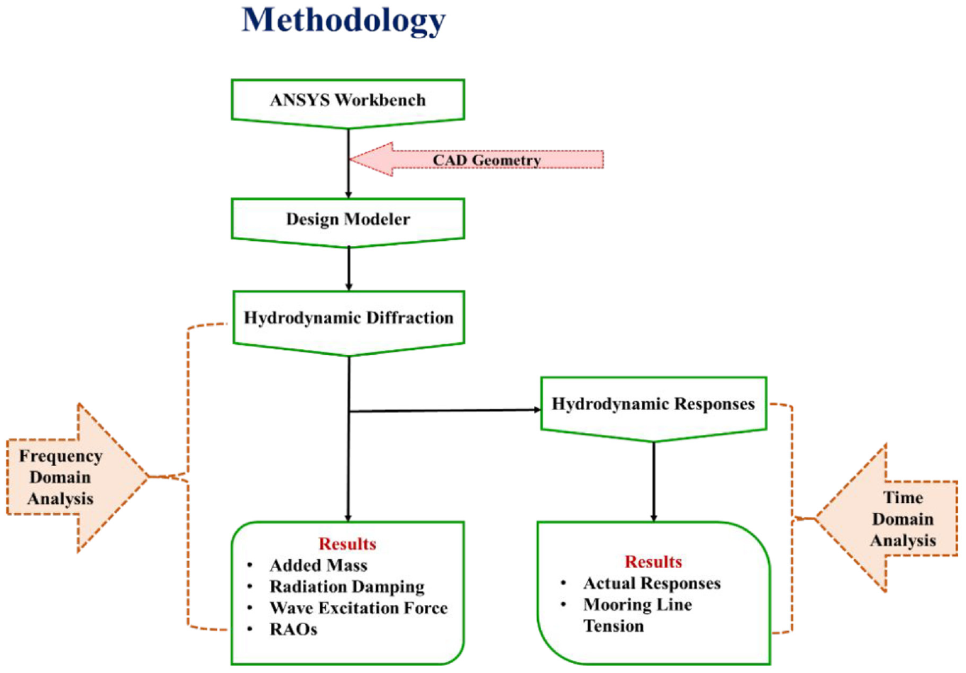
Methodology of present numerical work.
The numerical simulation is based on a linear wave, Morison and stokes second-order theories.
Linear potential theory:
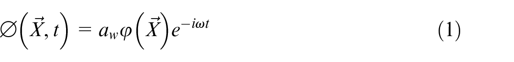
Where
Morison element forces:
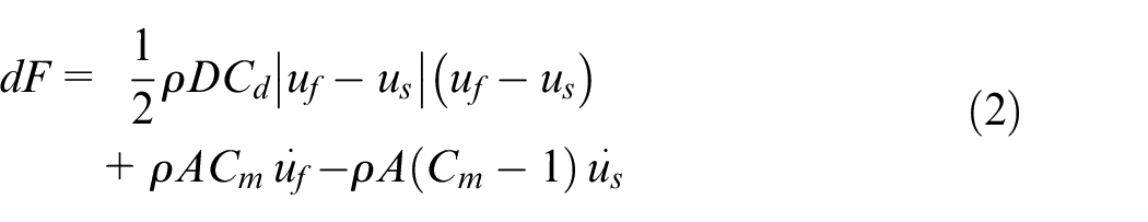
Where,
D = characteristic drag diameter
A = cross-sectional area
Stoke’s second-order theory:
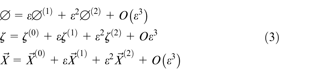
where ε → 0
where the superscript (0) denotes the static values, and superscripts (1) and (2) indicate the first and second-order variations concerning the perturbation parameter.
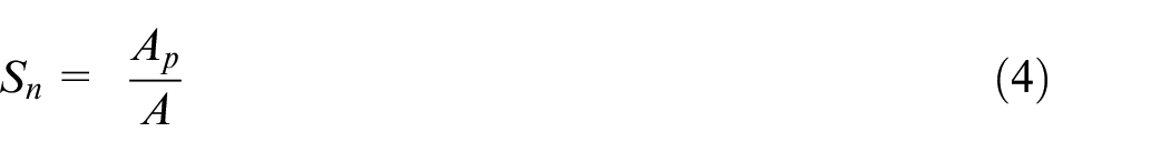
The net’s hydrodynamic force is intertwined with its solidity ratio (Sn), which is defined as the ratio of the projected area (Ap) covered by the threads to the entire area of the net panel (A), that is,
Net solidity is an important parameter that affects the hydrodynamic parameters such as transmission, reflection, energy loss, motion responses, and mooring line tension of the floating fish cage. In the present study, a knotted HDPE diamond mesh net and an empirical formula are used to determine the current fishing net’s net solidity.
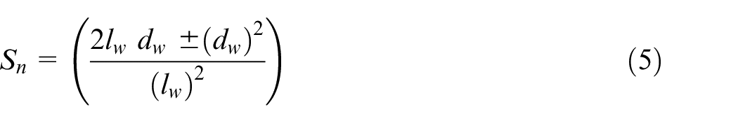
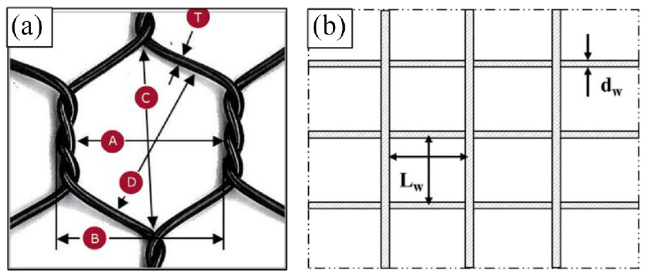
Where Sn is solidity ratio, lw is the length of twine, and dw is diameter of the twine. For knotted net “+” addition of squared diameter and for knotless net “−” subtraction of the squared diameter is used to find out the net solidity. A knotted HDPE diamond mesh net is used for experimental study, whereas a knotless diamond mesh net is used for numerical simulation to avoid complexity and simulation running time (Figure 4).
(a) Knotted net for experimental work and (b) knotless net for numerical simulation.
Numerical method of prototype cage
In the present numerical study, the experimental model is scaled up to 1:75 to meet prototype requirements and ANSYS AQWA is used to calculate added mass, radiation damping, RAOs, and mooring line tensions. Detailed methodology is provided in Figure 3. ANSYS AQWA is an established commercial entity that has been broadly used and verified by numerous researchers by contrasting its outcomes to competitive simulation tools and experiments.11,20
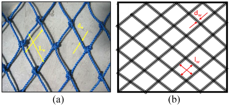
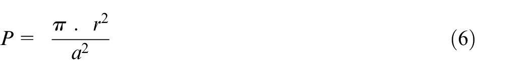
Figure 5 shows the simulated fish tank, which is square in shape and has a partly perforated wall (wave barrier) at the top to deflect intense surface waves and safeguard the fish from drifting objects and predators. The prototype fish cage dimensions and properties are provided in Table 1. The upper part (wave fencing) of the cage adjoining the Still Water Line (SWL) of 6 m high (3 m emerged and 3 m submerged in reference with SWL) porous wall, to dissipate waves of 3 m high. Four cases of with and without porosity of wave fencing are considered. Three different diameters of 0.5, 0.6, and 0.7 m of porous holes are considered at wave fencing. The presence of a porous hole in fencing provides energy loss, transmission and creates a reasonably calm environment for fish farming. Four truss girders (above water) and two girders at the base connect the square cage, which behaves as a unified solid body. The fish cage has four connecting points where four catenary chains are connected in order to have station keeping. The mooring lines are situated at the points where the bottom of the pontoons connects to the cage for the purpose of minimal interaction between the mooring lines and the cage’s structure and to consolidate the mooring lines into a compact seabed footprint.
Fish cage prototype model in ANSYS AQWA.
Partial porous wall (wave barrier)
Strong waves must be attenuated to conquer selected site limits for offshore fish farming. To restrict wave energy transmission within the cages, the cage structures need to be designed and equipped with wave dissipative members. 21 Thin porous structural members adopted in a breakwater system could be a feasible method to protect coastal assets. 22 Hence, a porous collar system is considered in the present model, which can reduce wave transmission and reflection. Table 3 provides the detailed hole sizes used to create the various porosities and Figure 6 describes pore arrangement.
Porosity of wave fencing details.
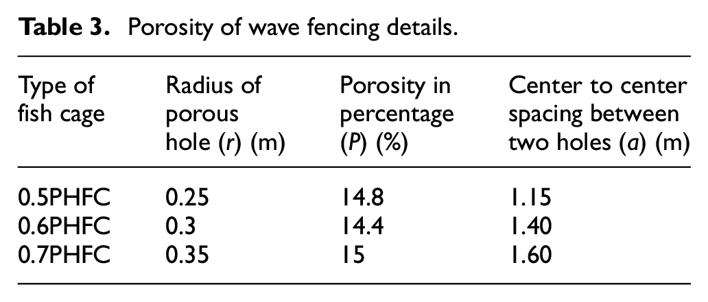
The center to center spacing of porous hole can be calculated as follows, 23
where “a” is spacing between two holes, P is porosity, and “r” radius of porous hole.
Wave fencing details: (a) non-porous wave fencing, (b) 0.5PHFC, (c) 0.6PHFC, and (d) 0.7PHFC.
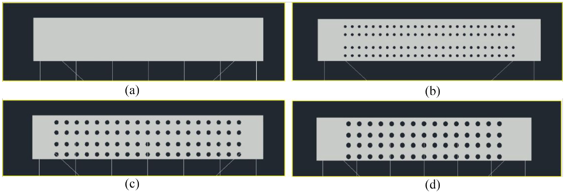
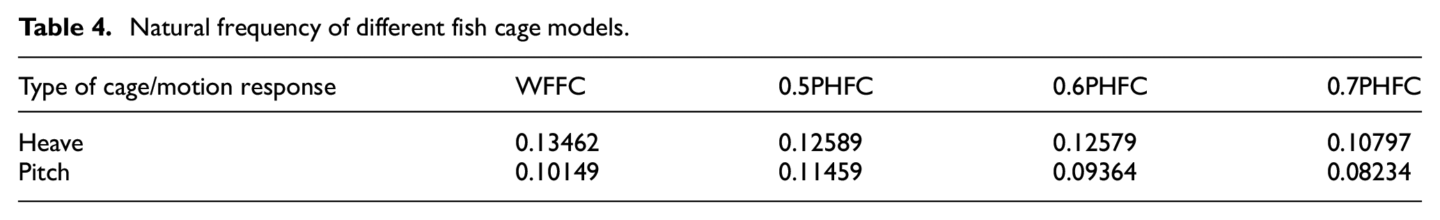
Natural frequency
The frequency at which a system oscillates in the absence of any driving or damping force is referred to as the natural frequency or Eigen frequency. In three-dimensional analysis, the restoring forces are available for heave, pitch, and roll motions. Table 4 shows the natural frequencies for different fish cage models obtained from ANSYS AQWA.
Natural frequency of different fish cage models.
Numerical net system
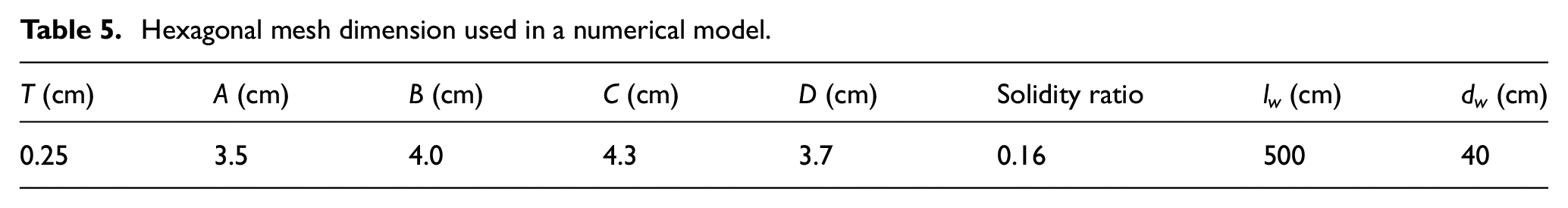
An equivalent net of EcoNet is used for the current cage in numerical analysis. AKVA Group develops EcoNet and it is a non-fiber material with a firm surface which is resistant to marine fouling and simple to clean in the water. It is manufactured with an ultra-strong yet lightweight PET (Polyethylene Terephthalate) that has been proven to endure 14 years in the water. 24 The solidity ratio of net is defined according to equation (1) and empirical formulae are provided for the square/diamond net. EcoNet is hexagonal in shape and there are no particular formulae to calculate net solidity. The solidity ratio is calculated as the projected area ratio to the total area. The exact net size cannot be modeled because the number of elements is in millions and requires a sophisticated workstation to simulate. An equivalent net is introduced to overcome this issue and accounts for the same hydrodynamic forces as the physical net. The equivalent diameter dw can be obtained from a given twine length lw by:
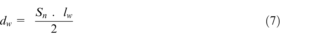
The EcoNet and numerical net model are shown in Figure 7 and the solidity ratio can also be calculated with the same principle given in equation (4). Table 5 provides the dimensional details of EcoNet with a net solidity of 0.16. To obtain an equivalent diameter of dw = 0.4 m for an assumed twine length of lw = 5 m, the same net solidity ratio of 0.16 has been considered by using equation (7).
(a) EcoNet and (b) equivalent net.
Hexagonal mesh dimension used in a numerical model.
Mooring lines
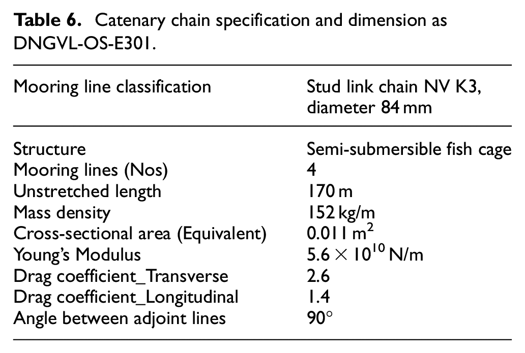
The square fish cage is moored with four catenary chains attached at fairleads attached to the bottom of its pontoons (Figure 8). Due to their extreme size and economic consideration, offshore fish cages often adopt a multi-mooring line mooring system. In addition to creating a large benthic footprint, multiple mooring lines complicate installation and create off-balance tension forces on windward and leeward sides. This mooring line arrangement is expected to result in a more balanced interlocking motion between the anchor lines and the floating structure and a simpler and more cost-effective solution. The mooring line configuration is provided in accordance with DNVGL Standards and Rules.25–27 The detailed mooring line configuration is provided in Table 6.
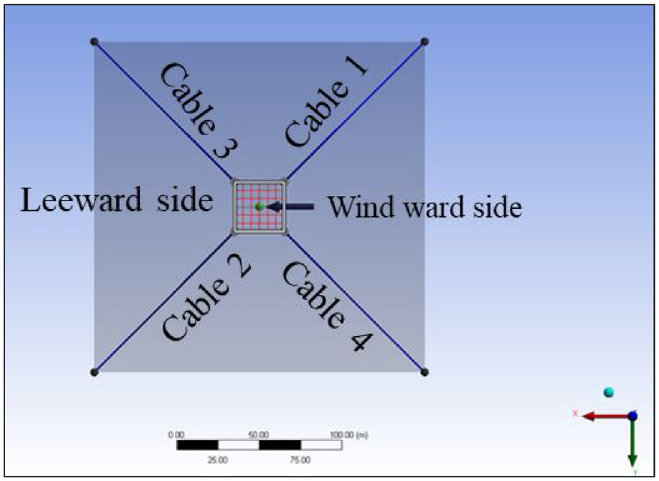
Top view of fish cage after providing mooring lines.
Catenary chain specification and dimension as DNGVL-OS-E301.
Meshing details
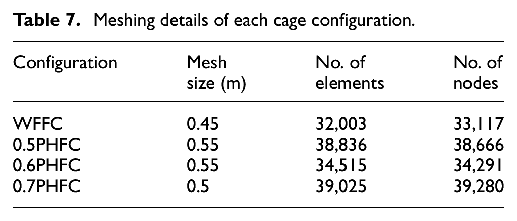
A hybrid model that combines panel elements and Morison tubular elements is used for numerical modeling. The top wave fencing/porous wall and bottom pontoons are modeled by using panel elements, and the remaining members are modeled as Morison tubular elements. The meshing detail of each cage is presented in Table 7.
Meshing details of each cage configuration.
Results and discussions
Validation of numerical work
A comparison of the experimental and numerical results of the cage is depicted in Figure 9. The present experimental study was carried out in a two-dimensional regular wave flume laboratory. The motion responses and mooring line tension are presented for 8 and 10 cm wave heights and eight different wave periods. The numerical results of motion responses in both heave and pitch motions show a 10%–15% variation with experimental results. This is due to the fact that the linearized drag was not considered in the present numerical model because the option is only available for irregular wave environments in the software. To compare with the experimental results same boundary conditions and wave characteristics were considered. Further, the present numerical model exhibits ±10%–15% variation in the mooring line tension for wave periods of 0.8–2.2 s. The same trend is observed for both windward and leeward side mooring lines. Apart from this minimal error, the present numerical model provides good agreement of results with experimental results.
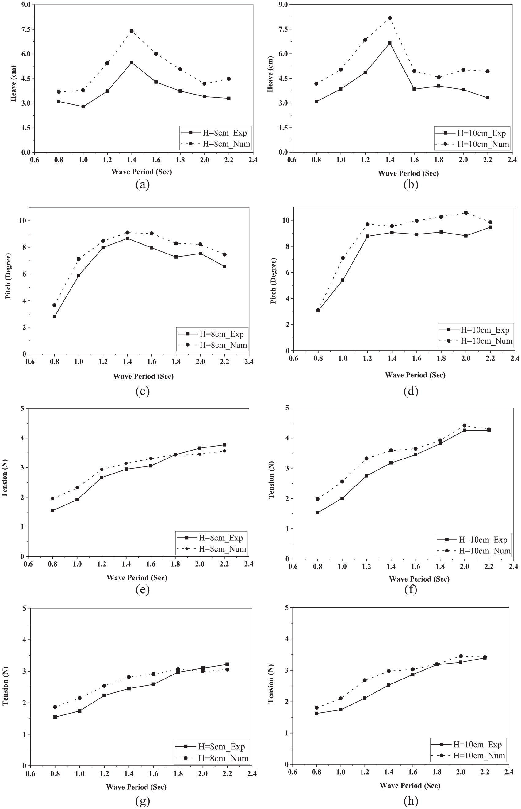
Experimental and numerical validation for a model scale: (a) heave_8 cm, (b) heave_10 cm, (c) pitch_8 cm, (d) pitch_10 cm, (e) tension_seeward_8 cm, (f) tension_seeward_10 cm, (g) tension_leeward_8 cm, and (h) tension_leeward_10 cm.
Numerical analysis of prototype
Frequency domain analysis
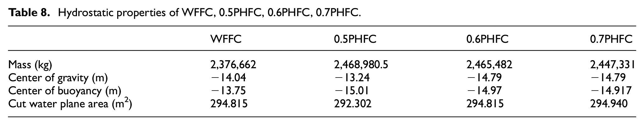
The hydrodynamic diffraction module was used for frequency domain analysis to determine hydrostatic and hydrodynamic properties of free floating and mooring objects, such as added mass, radiation damping, and RAOs. The hydrostatic properties of each case are presented in Table 8.
Hydrostatic properties of WFFC, 0.5PHFC, 0.6PHFC, 0.7PHFC.
Added mass
In a fluid domain, an acceleration or deceleration body moves through a fluid, mass of surrounding fluid attached to the body also accelerates which is called added mass.
The added mass results are presented in the graphical form as a correlation between the non-dimensional parameter, f/f1 and added mass for heave and pitch motions. Figure 10(a) shows the added mass in free-floating conditions in a heave motion. It is observed that added mass of all the porous hole fencing cages decreases as the frequency increases upto the natural frequency of the structure and then gradually increases, reaching a steady value. The added mass of wave fencing cage without porosity decreases with an increase in frequency upto the natural frequency of the structure and exhibits the least added mass in heave compared to other three cages. Similarly, Figure 10(b) represents the added mass behavior in the pitch motion of four different cages. The added mass of the all-porous cages increases with an increase in frequency upto the natural frequency ratio and further decreases with an increase in frequencies and follows a similar trend. However, the cage with a porosity of 15% has a higher added mass in pitch and exhibits a similar trend of the other three cages.
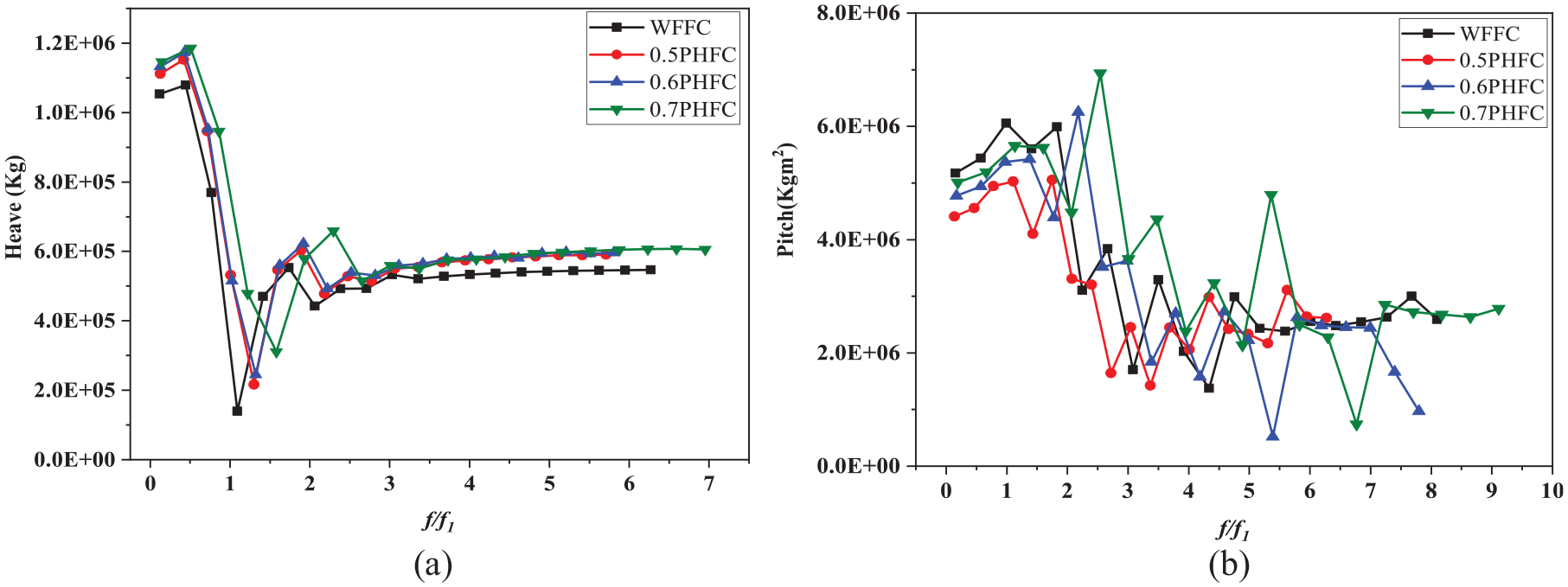
Variation of added mass in (a) heave and (b) pitch.
Radiation damping
The radiation damping results are presented in the graphical form as a correlation between the non-dimensional parameters of frequency ratio (f/f1) and radiation potential damping for heave and pitch motions.
Figure 11(a) shows radiation damping in free-floating conditions. It is learnt that radiation damping increases with increased frequency ratio in heave motion and reaches maximum radiation damping value in the proximity of frequency ratio (f/f1 = 1) for all cages. Also, an additional peak is obtained in the vicinity of f/f1 = 2 for all cages and reaches steady conditions with increased frequencies. The cage with a porous hole diameter of 0.7 m exhibits the highest radiation damping of (5.41 × 10⁵ N and 4.59 × 10⁵ N) consecutively near the frequency ratio of harmonics (f/f1 = 1 and 2). It is understood that all the cages in heave motion exhibit a similar trend. Further, the behavior of all cages in pitch motion of radiation potential damping is almost identical except at the peak for four different configurations. The cage with a porous hole diameter of 0.5 m (0.5PHFC) exhibits a maximum radiation potential damping of 3.5 × 10⁷ N at a frequency ratio of 3.5.
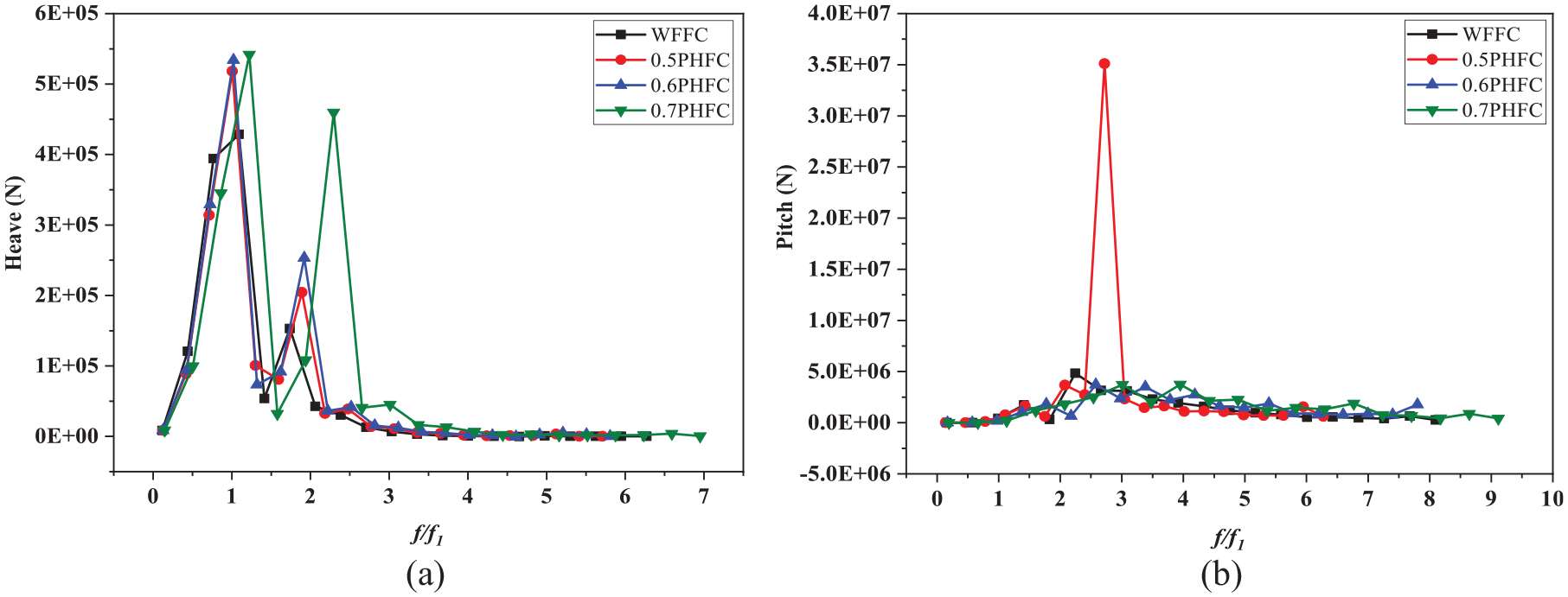
Radiation damping in (a) heave and (b) pitch.
Response amplitude operators (RAOs) without mooring
Floating structures are characterized using RAOs, which are engineering statistics that can be used to predict how they will behave at sea. In the present study, the RAOs of a fish cage in heave and pitch motion at offshore are studied. The variation of RAOs for the range of frequency ratio is projected in Figure 12 for different cages.
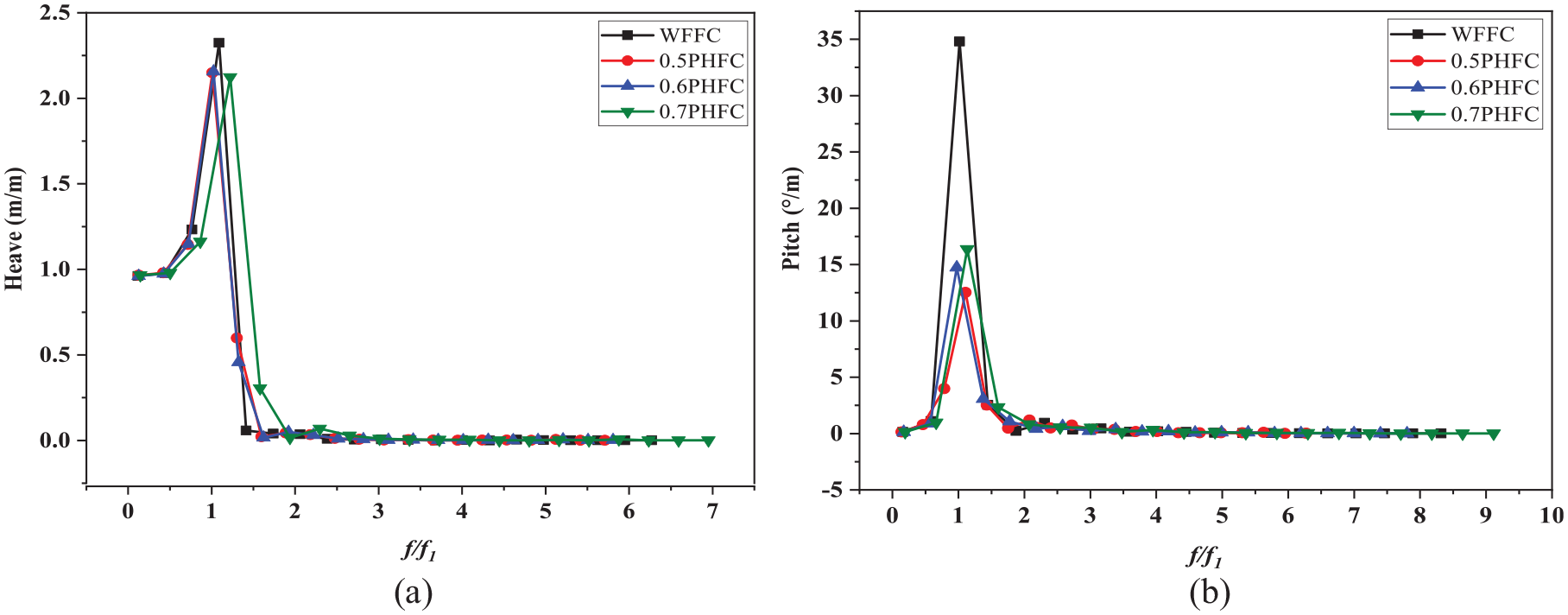
RAO of a different fish cage without mooring line: (a) heave and (b) pitch.
The heave motion of each case increases with frequency ratio upto the resonant frequency ratio, then the response decreases to a minimum and remains constant with further increase in frequency ratio. The cages of no porous condition exhibit the highest RAO in heave and which is about 2.32 m/m, followed by 0.6PHFC. The same trend is obtained in pitch motion for all cages and among all cages, the cage of without porosity exhibits the highest pitch RAO of 34 (°/m) followed by 0.7PHFC. Beyond the maximum response, all the cages behaved identically and provided a constant RAO. It is concluded that the non-porous wall cage exhibits the highest RAOs in both heave and pitch motions.
Wave excitation force
Wave excitation force is a combination of both Froude-Krylov and Diffraction force. Figure 13 illustrates the wave excitation force of all the cages and it decreases with an increase in frequency and reaches a minimum in the proximity of resonant frequency. Beyond the frequency ratio of 1.5, all the cages follow the same trend with a meagre difference. In pitch motion, the wave excitation force of all cages follows a similar trend. The cage with a porous hole diameter of 0.7 m exhibits a drastic increase near the frequency ratio of 2.5, followed by a non-porous wall cage.
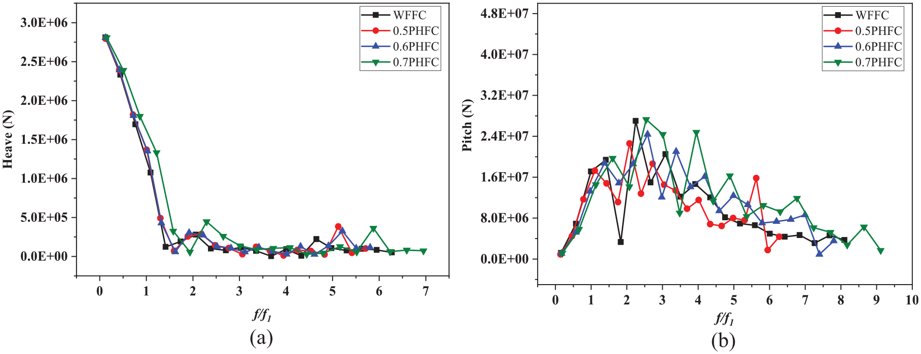
Wave excitation force: (a) heave and (b) pitch.
Time domain analysis
Actual responses
The response of all the cages with the moored condition obtained from time domain analysis is presented in Figure 14, for both heave and pitch motions.
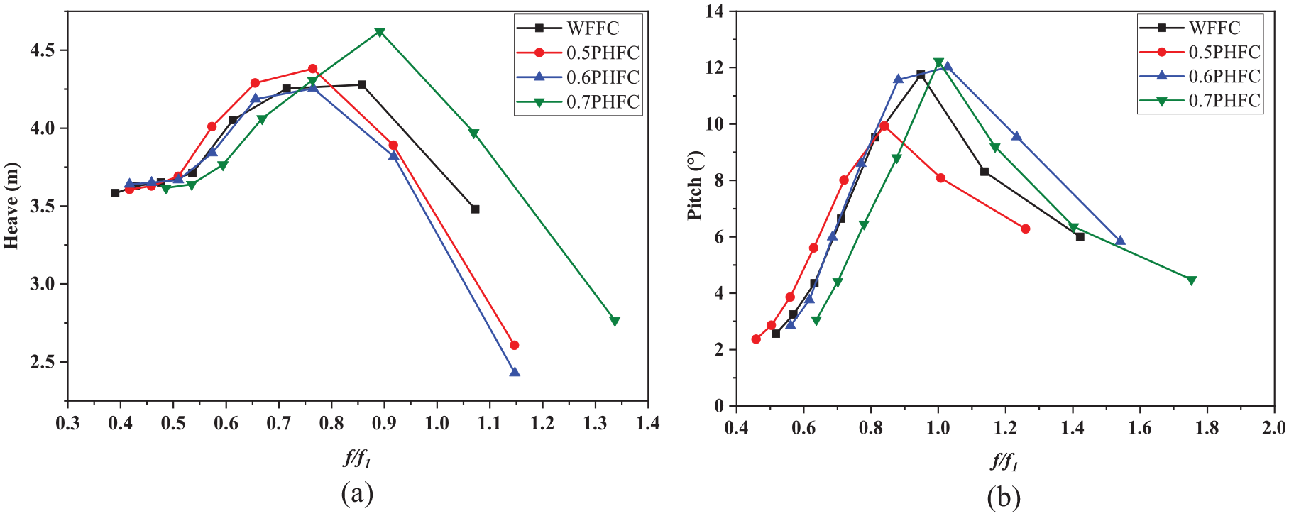
Actual responses of a different fish cage with mooring line: (a) Heave and (b) Pitch.
It is observed that the difference in heave and pitch responses between each cage is meagre. The heave response of each cage follows a similar trend. Also, it is understood that with increased frequency, heave motion increases and reaches a minimum value in the proximity of a frequency ratio of 0.8–1.0. The cage configuration of 0.7PHFC gives the highest heave and pitch responses of 4.62 m and 12.26°, respectively. In pitch condition, the response increases with increasing frequency, reaches a maximum in the proximity of resonant frequency, and reduces with increased frequency. The cage with a porous hole diameter of 0.6 m performs better in heave response and the cage with a hole diameter of 0.5 m performs better pitch motion.
Comparison of frequency and time domain RAOs
The Response Amplitude Operators of all four cages are analyzed in both frequency and time domains. The results are illustrated in Figures 15 and 16 for heave and pitch, respectively. The results for each cage follow a similar trend in both heave and pitch motions. The frequency domain analysis is carried out for each cage under free-floating conditions and in time domain analysis, moored condition is considered. The difference in the magnitude of RAOs is due to the presence of mooring lines in time domain analysis. The Wave Fencing Fish Cage (WFFC)/nonporous fencing cage obtains the highest RAOs in both frequency and time domain analysis for heave and pitch motions.
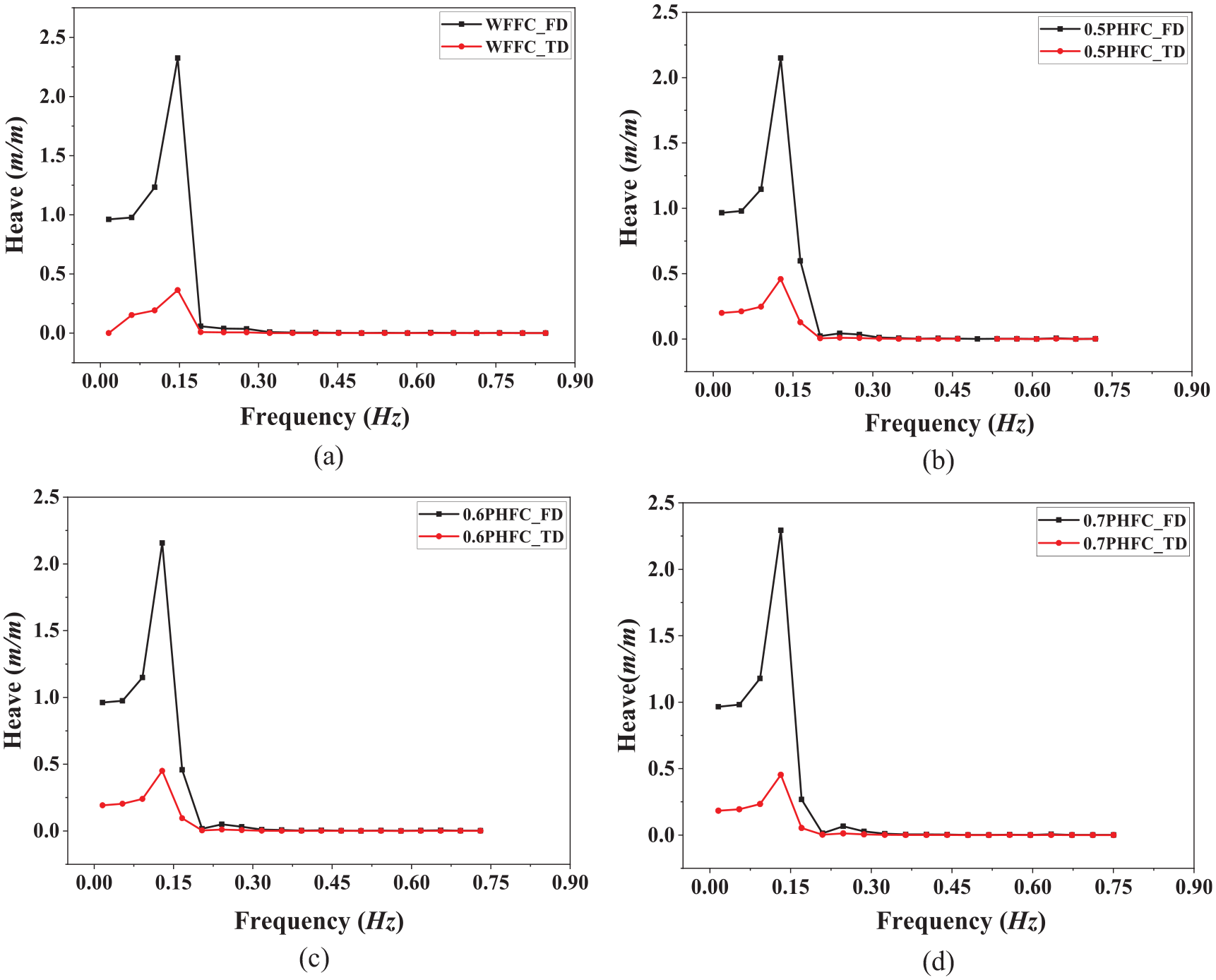
Comparison of heave RAOs in both frequency and time domain analysis: (a) WFFC, (b) 0.5PHFC, (c) 0.6PHFC, and (d) 0.7PHFC.
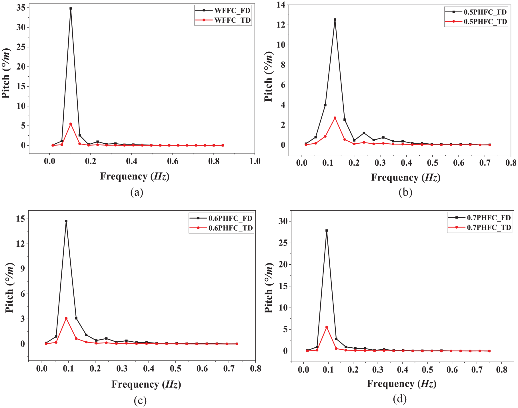
Comparison between frequency and time domain analysis of RAOs in pitch motion: (a) WFFC, (b) 0.5PHFC, (c) 0.6PHFC, and (d) 0.7PHFC.
Mooring line tensions
Figure 15 shows mooring line tension in regular wave conditions by comparing each case of WFFC, 0.5PHFC, 0.6PHFC, and 0.7PHFC in time domain analysis (Figure 17).
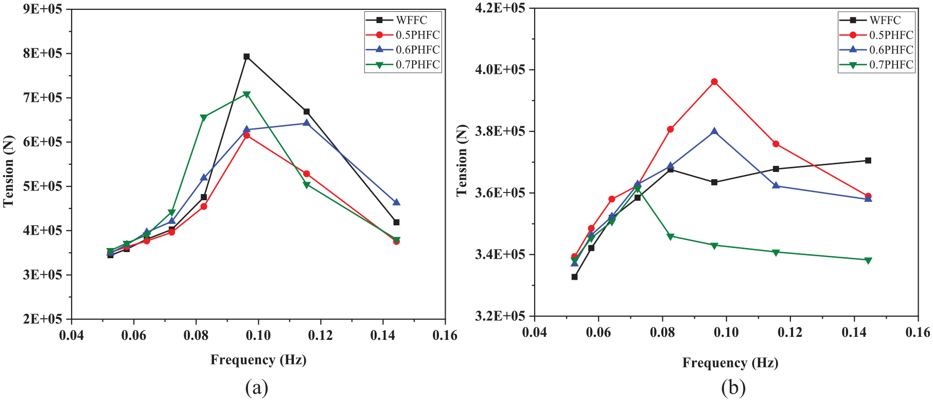
Mooring line tension of different fish cage: (a) Windward and (b) Leeward.
The mooring line tension on the windward is always greater than the leeward side. Also, the tension increases with increased frequency and reaches a maximum for all conditions near the frequency of 0.10 Hz and decreases till 0.14 Hz. The mooring line tension on the leeward side increases with frequency and attains its maximum between the frequency range of 0.07–0.10 Hz for the different cages considered. The cage with no porous holes has maximum mooring line tension of 7.92 × 10⁵ N on the windward side and the cage with a porous hole diameter of 0.5 m (0.5PHFC) has a maximum mooring line tension of 3.96 × 10⁵ N in the leeward side. The difference in percentage of maximum mooring line force is about 45%.
Conclusions
In the recent years, the offshore aquaculture industry has been growing exponentially, and considerable research is needed to develop sustainable infrastructure. The present study focuses on porous wall fencing offshore fish cages, which helps to attenuate the wave energy. The wave fencing without porosity and three different porous hole diameters of 0.5, 0.6, and 0.7 m with a percentage of perforations (14.4%–15%) were considered. A detailed numerical study was conducted on four different cages for regular wave conditions using ANSYS AQWA. A series of physical tests and numerical simulations were performed on a scaled model to validate the present numerical method. Frequency domain and time domain analysis were carried out for each cage to obtain the hydrodynamic parameters such as added mass, radiation potential damping, wave excitation force, motion responses, and mooring line tensions. The numerical results exhibit ±10%–15% variation with experimental results of the scaled model in both heave, pitch and mooring line tension.
The non-porous wave fencing cage has a comparatively lesser added mass in heave and higher added mass in pitch motions, respectively. However, all cages followed a similar trend for the added mass. The cage with 0.7 and 0.5 m porous hole diameter cages exhibits positive peaks in pitch and heave motions of radiation potential damping, respectively, due to coupled motions. The configuration of WFFC showed higher RAOs in both heave and pitch motions among four cages. The wave excitation force, RAOs in heave and pitch motions are analyzed, and all the cages followed a similar trend. The motion responses and mooring line tensions were examined in time domain analysis. The non-porous wave fencing cage obtained a higher mooring line tension of 7.92 × 10⁵ N in the windward direction than other cages and 0.5PHFC has a lower tension in the windward and higher of 3.96 × 10⁵ N in leeward. Considering the hydrostatic and dynamic wave conditions, the present study concluded that the 0.5 m porous hole diameter (0.5PHFC) cage performed better in all wave conditions than the other three cages.
In the present numerical work, the porous hole diameters of 0.1–0.8 m were considered initially, but due to meshing and connectivity issues, the porous hole diameters are restricted between 0.5 and 0.7 m. The linearized drag for the structure is not considered for the present study due to unavailability of an option for regular wave conditions and it will be incorporated into future studies for irregular waves. Future studies will consider different wave heights, submergence depths, and irregular waves. Wave transmission and reflection studies will be conducted and suggest the optimum porous hole diameter for better performance.
Footnotes
Appendix
Declaration of conflicting interests
The author(s) declared no potential conflicts of interest with respect to the research, authorship, and/or publication of this article.
Funding
The author(s) received no financial support for the research, authorship, and/or publication of this article.