
Abstract
Coastal erosion is a global concern that has been augmenting due to the natural evolution of beaches, human activities and sea-level rise. One of the eco-friendly shore protection methods is to dissipate the wave energy by constructing offshore breakwaters. Conical pile head breakwater (CPHB) is one of the eco-friendly innovative offshore structures consisting of closely spaced piles with an enlarged cross-sectional area (conical pile head) in the vicinity of the free surface. In the present study, perforations are incorporated over the conical pile head to achieve higher efficiency by promoting energy dissipation. The influence of the perforations on the performance characteristics, namely wave transmission (Kt), wave reflection (Kr) and energy dissipation (Kd) of the perforated CPHB is comprehensively investigated through physical model studies. The effect of perforations and their distribution around the pile head (Pa), percentage of perforation (P) and size of perforations (S/D) on the wave attenuation characteristics are evaluated to arrive at an optimum configuration. The study is carried out under monochromatic waves of varying wave height (0.06–0.16 m) and wave period (1.4–2 s) at different depths of water (0.35, 0.40 and 0.45 m). A minimum Kt of 0.58 associated with Kr of 0.26 and Kd of 0.78 is obtained with an optimum configuration of Pa = 50%, P = 19.2% and S/D = 0.25. The Kt of the proposed CPHB is about 19 to 35% lesser than that of the perforated hollow pile breakwater under matching test conditions. Overall, providing the perforations is found to be effective in enhancing the wave attenuation capability by up to 12.4%. Further, empirical equations are formulated and validated with the experimental data. The empirical equations estimate the Kt and Kr values accurately with a high coefficient of determination (R2 ≥ 0.90).
Introduction
Rubble mounds and caisson type of breakwaters are also known as conventional breakwaters. Even though the conventional breakwaters are massive, they are essential for the harbours to achieve tranquillity conditions. Whereas, the conventional breakwaters become uneconomical for marinas, fishing harbours and shore protection works where partial protection from the waves is generally sufficient.1–4 In addition, minimal wave activity is necessary for the coastal protection works to ensure the free passage of sediments and seawater exchange to maintain water quality. Hence, there is a need for research on environmental friendly breakwaters. Environmental friendly breakwaters are the ones those consume less resources, easy to construct, allow the exchange of water between the sea and lee side, facilitate unhindered movement of marine life and do not hamper the sediment movement. 5 These pile structures allow some amount of wave energy to pass on to the lee side and allow an exchange of water and sediment, thus offer only partial protection. Pile breakwater and pile-supported breakwaters are gaining momentum due to the advantages over conventional breakwaters. The permeability nature of these breakwaters makes them more suitable for shore protection works since the sediment movement is uninterrupted. The pile breakwaters become economical in deep water as it requires lesser construction material than the conventional breakwaters. 6 In addition, the pile breakwaters consume lesser resources and occupy a comparatively smaller area on the sea bed and are therefore economical than the conventional breakwaters, specifically when constructed in deep water.7–9 Pile breakwaters are generally preferred economical option when the hard stratum is absent at a nominal depth and wave climate is moderate.10,11
Pile breakwater
In the past, many researchers have studied the performance of pile breakwaters, which is also referred to as conventional pile breakwaters (Refer Figure 1(a)). They consist of closely spaced prismatic piles and are generally constructed parallel to the shoreline. One of the earliest known experimental work was by Costello. 12 It was reported that doubling the number of pile rows leads to a reduction of the wave transmission of around 18%, irrespective of the density and configuration of the piles. Closely spaced piles as a coastal protection structure were undertaken by Weigel, 13 where the transmitted wave height in the case of experimental work was found to be about 25% more than the theoretical prediction. Bovin 14 investigated the slotted vertical wall breakwater and concluded that the shape of the holes had an insignificant effect on the energy dissipation characteristics of the perforated structure. A maximum of 15% reduction in wave transmission was achieved by adding an additional row of piles by Herbich and Douglas. 15 The staggered arrangement of piles resulted in lower wave attenuation with reduced reflection compared with the regular configuration. 16 Truitt and Herbich 17 indicated that the mathematical relationships developed by Hayashi et al. 18 and Hayashi et al. 19 for a single row of piles against monochromatic waves might apply to random waves too. Experimental work was carried out by replacing the circular piles with rectangular shaped piles, as illustrated in Figure 1(b). 20 It was reported that the transmission coefficient (Kt) of rectangular pile breakwater was indirectly proportional to the incident wave height whereas, the reflection coefficient (Kr) was directly proportional. Zhu and Xie 21 derived theoretical equations for estimating the wave transmission and reflection coefficients of single row rectangular pile breakwater using Rayleigh expansion method. Further, numerical modelling studies by Mojtahedi et al. 22 proved that the pile breakwater with rectangular shaped piles has about 7% to 30% higher reflection than the circular-shaped piles. Single row 23 and two rows 24 of pile breakwater under solitary waves (resemble tsunami waves) were numerically investigated using the computational fluid dynamics tool OpenFOAM. In the case of two rows, the front row of piles experienced higher wave run-up and impact force due to the sheltering effect. 24 Some of the important pile structures investigated by various authors available in the literature and relevant to the present work are illustrated in Figure 1.
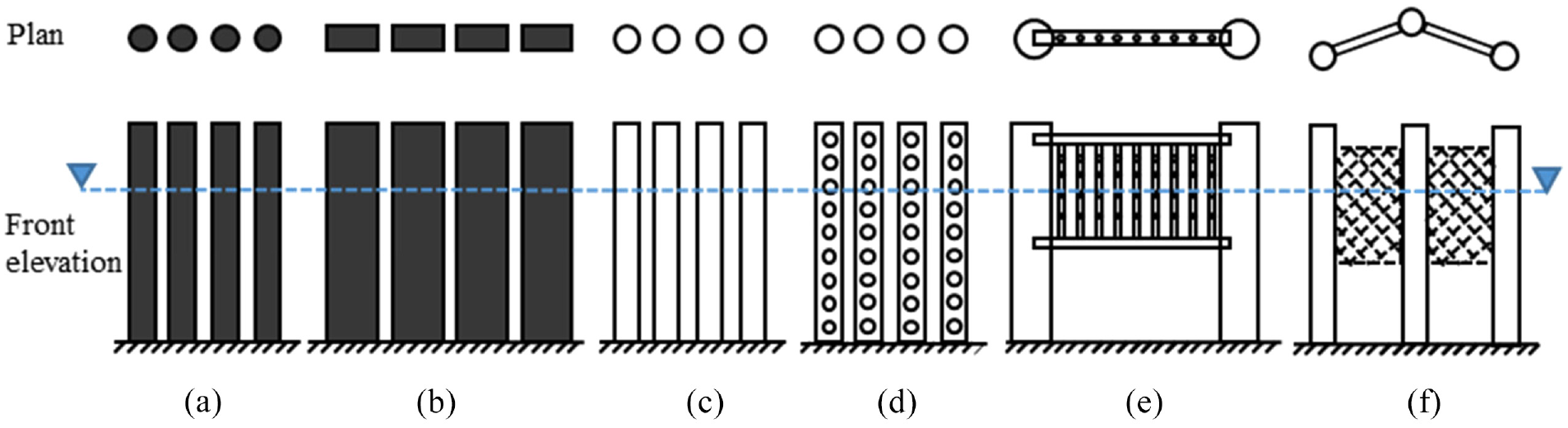
Typical representation of pile structures investigated by various authors: (a) conventional pile breakwater, (b) rectangular pile breakwater, (c) hollow pile breakwater, (d) perforated hollow pile breakwater, (e) suspended perforated pipe breakwater and (f) zigzag porous scrreen breakwater.
In order to enhance the performance of the structures, perforations were introduced on the surface of the structures. The perforations were expected to increase the wave-structure interaction resulting in higher energy dissipation. Rao and Rao25,26 investigated the influence of perforations on the transmission and reflection characteristics of the suspended perforated pipe breakwater (Refer Figure 1(e)) by providing the pores on the suspended pipe breakwater. The perforated pipes with 25% of perforations were found to be effective in enhancing wave attenuation by about 10% to 14% with lesser reflection than the similar non-perforated structure. The experiments carried out by Rao et al. 27 on two rows of perforated hollow pile breakwater revealed that the wave attenuation capability of the perforated hollow pile breakwater is better than that of non-perforated one. Further studies on two rows of perforated hollow piles by Rao et al. 4 proved that the performance characteristics of the hollow structures could be enhanced by introducing the perforations. The performance of the two rows of perforated piles was investigated by Anuar and Sidek. 28 The study determined that the size of the perforation has got a significant influence on the wave attenuation characteristics. Some of the examples of already built pile type of structures are Pass Christian Harbour in Mississippi, Bay St. Louis in the USA, Port of Osaka in Japan, 15 Port of Ust-Luga in Russia, Hanstholm in Denmark and Tanah Merah in Singapore. 5
Pile-supported breakwaters
Even though the conventional pile breakwater proved to be efficient, construction of piles at closer spacing may pose practical difficulties at sites. To overcome these constraints, pile-supported breakwaters were proposed where a large barrier was provided on a series of piles located at a larger spacing. The suspended pipe breakwater was introduced by Mani and Jayakumar,
3
where an array of piles were mounted on the frame, which was suspended with the help of support piles. The construction cost of the suspended pipe breakwater was reported to be 40% cheaper than the conventional pile breakwater. Many studies were conducted by mounting different types of barriers/structures on the pile supports. The various shapes considered are T-type,
29
Present research work
It is a well-known fact that the orbital motion of the water particles is maximum near the free surface and reduces gradually with the depth, as shown in Figure 2. With this logic, the idea of conical pile head breakwater (CPHB) is formulated. The typical line diagram of the proposed structure is shown in Figure 3, where the cross-sectional area of the pile is tapered, similar to that of wave orbital motion profile. The proposed concept of perforated CPHB may overcome the difficulties due to closer construction of conventional pile breakwater with improved efficiency. Due to the presence of gaps between the individual pile head units, the perforated CPHB structure does not interfere with the littoral drift and permits the passage of water and aquatic life.
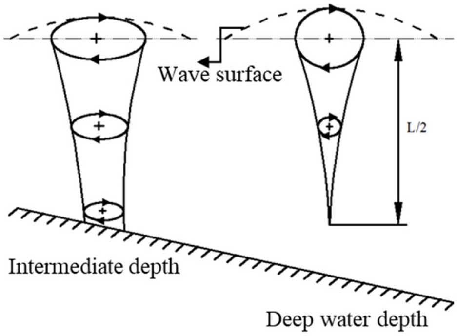
Orbital motion of water particles in intermediate and deep water conditions. 45
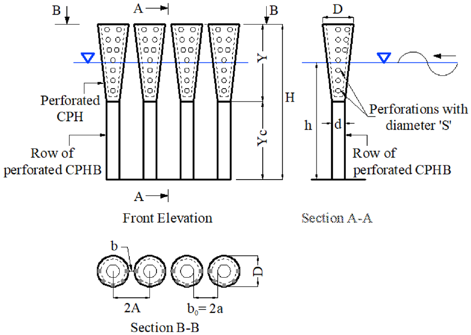
Typical diagram of proposed perforated CPHB in the present study.
The wave attenuation in conventional pile breakwater takes place due to the combined effects of flow separation, contraction, intense flow through gaps, vortex formation and eddy shedding. Due to the increased area of piles at the vicinity of the free surface where wave energy is concentrated, the proposed structure is expected to induce higher resistance against the wave propagation, which contributes to increased wave attenuation. Furthermore, during the wave-structure interaction, a certain amount of the water flows in and out of the conical pile head through the perforations, contributing to additional wave attenuation by inducing additional turbulence.
It is clear from the literature review that the wave energy dissipation for the perforated structures is higher than the non-perforated structures. The studies on the perforated pile breakwater4,25–28 revealed that the size, distribution and percentage of perforations play a significant role in increasing the wave attenuation capability of the structure. Therefore, the performance characteristics of the single row CPHB are investigated through physical model studies by introducing the perforations on the CPHB. The performance characteristics include wave transmission (Kt), wave reflection (Kr) and energy dissipation (Kd) coefficients. The experiments are conducted using the monochromatic waves by varying the wave height and period at different depths of water. Comprehensive research is carried out by varying the distribution area of perforation (Pa), percentage (P) and relative size of perforations (S/D, where S is the diameter of perforations and D is the top diameter of CPHB) to determine the influence of perforations on the performance of the proposed structure. The aim of the study is to arrive at the optimum configuration of the perforated CPHB, which is capable of attenuating the waves to a maximum extent, and the results are aligned on the same track. In order to evaluate the behaviour and the performance of the perforated CPHB, the Kt, Kr and Kd are compared with the other pile breakwaters and pile-supported breakwaters. Further, a set of empirical formulae are developed for Kt and Kr of the proposed CPHB by using the present study results.
Physical modelling details
Test facility
The experiments are carried out in a two dimensional fixed bed wave flume constructed in the Department of Water Resources and Ocean Engineering, National Institute of Technology Karnataka, Surathkal, India. The flume has a length of 50 m with a cross-section of 0.71 m × 1.1 m. A bottom hinged flap-type wavemaker is installed at one end of the flume, capable of generating monochromatic waves. A passive type wave absorber (spending beach) is constructed at the opposite end to dampen the incident wave energy (Refer Figure 4). It is provided with a coarse gravel layer as the base, topped with irregular shaped granite stones with approximate nominal diameter (Dn50) of 0.052 m. The beach dissipates a large fraction of the wave energy by causing the incident waves to break, uprush and percolate through beach material and discourage reflection. The beach slope employed in the present study (1:12) is gentler than that of the recommendations by various investigators (1:10 by Hughes 46 and 1:4 by Straub et al. 47 ) and the length of the wave absorber is about three times greater than recommended (0.75L by Lean 48 ) for archiving minimal reflection (less than 10%). Hence, wave reflection from the spending beach is incognisable in the present study.
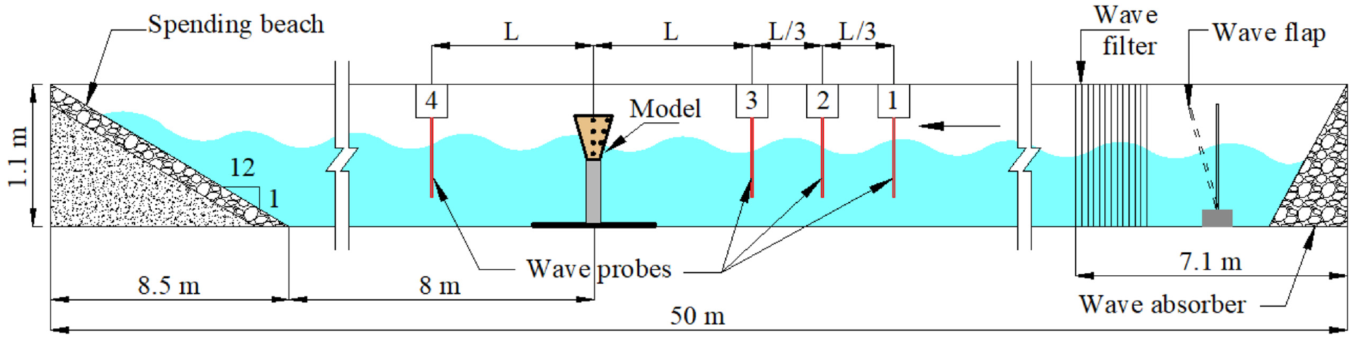
Experimental set-up of perforated CPHB in the wave flume.
An induction motor of 11 kW capacity can control the flap movement. An inverter drive can regulate the motor with a frequency range of 0–50 Hz. The flap is connected to the motor with the help of a flywheel using a bar chain mechanism. By changing the eccentricity of the bar chain, the desired wave height can be generated. The period of the waves can be altered by varying the frequency through an inverter. The bottom of the flume is provided with a smooth concrete bed. A provision is made for observation and photography by providing about 25 m of glass panel on one side of the flume. Before conducting the model studies, a particular combination of eccentricity and the generator’s frequency is determined to get the intended wave characteristics for all the sets of waves in the required depths of water considered in the study and the models are tested for only non-breaking wave climate. Depending upon the wavelength of generated waves, about 14–25 waves can be generated before the reflected waves between the model and wave maker cause re-reflection. However, in the present study, short burst of waves are generated to act on the model. As a result, the problem of reflection and re-reflection is avoided.
Model details
Considering the existing facilities of the two-dimensional wave flume at NITK Surathkal, the perforated CPHB and the wave parameters are modelled with the largest possible scale of 1:30, which is within the limit (1:10–1:50) suggested for the short-wave hydrodynamic models by Hughes. 46 The wave parameters and the model are simulated with the application of Froude’s law. CPHB structure is modelled by mounting the conical pile head (CPH) on the circular pile through bolted connection. As demonstrated in Figure 5(a), the CPH is 3D printed using Polylactic acid (PLA) material with an accuracy of 0.01 mm. The thickness of the CPH is 0.003 m. The supporting circular piles are fabricated using hollow galvanised iron pipes with a wall thickness of 0.002 m. For the firm support, an iron plate (0.012 m thick) is used at the base on which the supporting piles are attached by means of welded joints using mild steel collars, as presented in Figure 5(c).
Illustration of (a) 3D printing of perforated CPH, (b) variation of S/D under constant Pa and P and (c) experimental set-up of the structure.
The structural parameters of CPHB include the top diameter of CPH (D), height of CPH (Y) and clear spacing between CPHs in a row (b). The D and Y are expressed in non-dimensional form using maximum wave height considered for experimentation (Hmax), and b is expressed in terms of D. The influence of relative pile head diameter (D/Hmax), relative pile head height (Y/Hmax) and relative clear spacing between the CPHs (b/D) on the performance characteristics of non-perforated CPHB was investigated comprehensively in our previous study 49 and the optimum structural configuration was evolved (D/Hmax = 0.4, Y/Hmax = 1.5 and b/D = 0.1). In the present study, an attempt is made to further improve the performance of this CPHB structure by incorporating perforations. Further, the perforation characteristics such as distribution, percentage and size of perforations which play a significant role in the energy dissipation, are identified, and their ranges are selected based on the literature review.4,25,26
The calculation of the distribution of perforations (Pa) on the surface of CPH is illustrated in Figure 6. The wave climate (wave height and period) chosen is in accordance with the data obtained off the Mangaluru coast, west coast of India. 50 The data exhibited a wave height of less than 1.0 m during the fair-weather season and a maximum of 5.4 m in monsoon season, with a predominant wave period varying between 8 and 11 s. For this coast, the significant wave height reported is about 3.44 m with an average zero-crossing period of 10.4 s. For design purposes, the KREC Study Team. 50 recommended considering a wave height of 4.8 m. Therefore, the current study considers wave heights between 1.8 and 4.8 m and wave periods between 8 and 11 s, with a maximum wave height (Hmax) of 4.8 m. The present verification considers the normal wave attack (θ = 90°), which is the worst condition for any ocean structure wherein the complete structure confronts the incident waves and therefore proved to give conservative results.5,51 The performance of the perforated CPHB is tested under monochromatic waves. The literature review29,52,53 showed that the experimental results under monochromatic wave conditions would give conservative results than the irregular waves. Hence, the results of the present work conducted under monochromatic waves are reliable. The structural parameters, wave parameters and the details of perforation characteristics considered are enlisted in Table 1. The characteristics of the present studied structure and the test conditions are generally in line with those referred in the literature.
Typical tabulation of the perforation distribution (Pa) on the CPH surface area.
Governing parameters of physical modelling study.
The percentage of perforations is defined as the ratio of the total area of perforations to the corresponding CPH area on which the perforations are provided. The sensitivity study is conducted on the size of perforations (S) under the constant distribution of perforations and percentage of perforations, as demonstrated in Figure 5(b). It should be noted that the colour of the CPHs demonstrated in Figure 5(b) is only representative and no colour coding is adopted in the present study. The colour of the CPH model is chosen based on the material available at the time of 3D printing. To ensure the repeatability of the experimentation, each test case is investigated thrice.
Assumptions
The experiments are carried out on perforated CPHB under the following test conditions.
The incident waves are monochromatic in nature.
The seabed is rigid, which implies that the movement of sediments does not influence the performance of the proposed structure.
CPHB structure does not undergo structural deformation during the wave interaction.
The difference between the density of seawater and freshwater is not considered.
The frictional effects of seabed and sidewall are not accounted for.
The wave attacking angle is normal to the structure (θ = 90°).
Data acquisition and evaluation
The wave elevation data is recorded using the capacitance type probes manufactured by EMCON, Cochin, India. The surface tension errors are eliminated by applying a thin layer of Silica gel on the probe surface. Calibration of the wave probes is undertaken daily before and after conducting the experiments and the noted voltage variation is reliable (standard deviation <2%) as per Neelamani and Vedagiri. 53 A total of four wave probes are used for logging the wave data, as displayed in Figure 4. Three probes are situated on the seaside of the structure as per the recommendations by Isaacson. 54 The position of the probes is altered with respect to the wavelength of each wave generated. The composite wave data recorded in three probes are separated into incident and reflected wave components (Hi and Hr) by employing the three probes method proposed by Isaacson. 54 The transmitted wave height (Ht) is measured using the fourth probe placed on the lee side of the CPHB structure. This probe logs the overall water surface elevation caused by the combination of transmitted waves through CPHB structure and any secondary waves produced by overtopping. Using this data, the transmitted wave height (Ht) is calculated as the difference of surface elevations between the lowest and highest levels, resulting in maximum Ht. Further, the Kt is calculated by employing this maximum Ht. Therefore, the Kt reported in the present study is conservative. The Kt, Kr and Kd are calculated by employing the equations (1)–(3), respectively. Each case is repeated thrice and the average values of the coefficients computed are recorded as the test data.
Where Hi is the incident wave height, Ht is the transmitted wave height and Hr is the reflected wave height. The Kd is calculated using the law of conservation of wave energy.
Dimensional analysis
The dimensionless quantities are identified by carrying out the dimensional analysis by adopting Buckingham’s π theorem. The structural parameters (D/Hmax, Y/Hmax, Y/h and b/D), perforation parameters (S/D, P and Pa) and wave parameters (Hi/gT2 and h/H) which play a vital role in understanding the behaviour of perforated CPHB are identified. The predominant variable which has a significant influence on the performance characteristics (Kt, Kr and Kd) of the perforated CPHB are:
Wave attenuation mechanism of perforated CPHB
In conventional pile breakwater, part of the wave energy gets transmitted with partial reflection and energy dissipation. When the wave interacts with the structure, the flow gets separated due to the inertial resistance. The separated flow gets contracted between the pile gaps with an intensified velocity, which is responsible for vortex formation and eddy shedding in the main flow direction. All these processes lead to wave energy dissipation because of turbulence. Rao et al. 27 suggested that the performance of the conventional pile breakwater might be increased by inducing the additional turbulence.
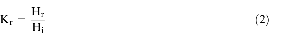
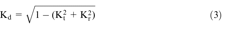
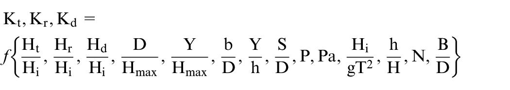
On this idea, the perforated CPHB is formulated. In addition to the above-stated mechanism, the increased area at the surface level provides a higher blockage area against wave propagation. As the wave crest passes through the CPH structure, some portion of the wave passes through the gaps and gets transmitted. Depending upon the wave height, the remaining portion may overtop and transmit the wave energy on the lee side and/or enter the hollow portion through the perforations (Refer Figure 7(a) and (b)). This water that is trapped in the hollow portion comes out and may interact with the incoming wave, which may result in reflection or energy dissipation, thus reducing the wave transmission (Refer Figure 7(c) and (d)).
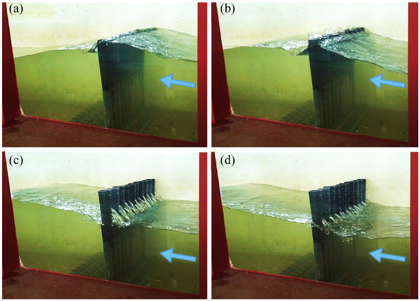
Demonstration of wave interaction with the CPHB (Pa = 50%, P = 19.2% and S/D = 0.25) at different time (t) instances for Hi = 0.16 m and T = 1.8 s at h = 0.40 m (h/H = 0.769): (a) t = 13.25 s, (b) t = 13.38 s, (c) t = 13.62 s and (d) t = 13.86 s.
Results and discussion
To arrive at the best performing model of perforated CPHB, the influence of perforation characteristics such as distribution of perforations (Pa), percentage of perforation (P) and size of perforation (S/D) are investigated. In the present work, 0.40 m is considered as the reference depth of water (MSL). Initially, the study is conducted at 0.40 m depth while studying the effect of Pa, P and S/D. Once after finalising the best performing configuration, the depth of water is varied to determine the influence of depth of water. The time histories of the incoming wave in the experiment and theory resolution (Stokes second order) for a typical case are compared in Figure 8.
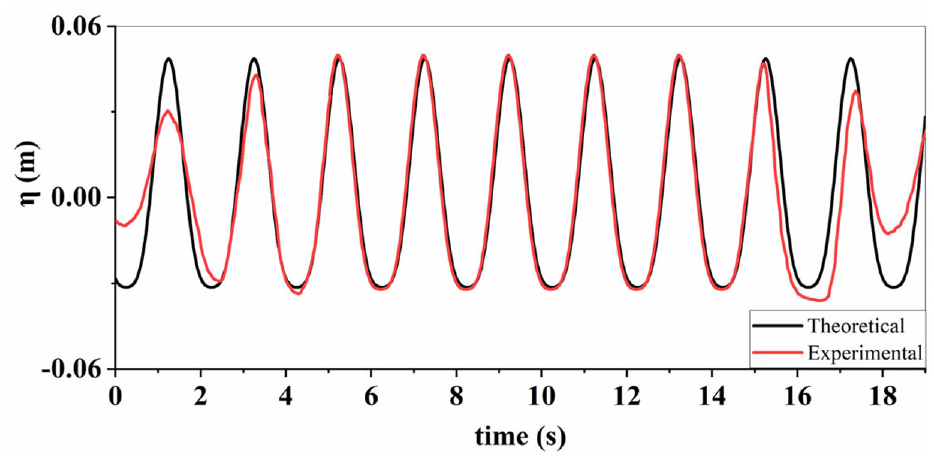
Comparison between the typical time history of incoming wave in the experiment and theory resolution for Hi = 0.08 m, T = 2 s and h = 0.40 m.
All the results (Kt, Kr and Kd) are analysed by plotting the data with respect to the wave steepness (Hi/gT2). The best fit lines are drawn for the data points to understand the trend of the results and they are projecting the behaviour to a reasonable extent. The analysis of the results is carried out with reference to the trend lines drawn. The scattering of the data points is also witnessed in the literature for the pile breakwater and pile-supported breakwaters by Bilici, 55 Kondo and Toma, 56 Ning et al., 57 Rao et al. 27 and Sundar and Subbarao. 11
Wave transmission characteristics (Kt)
Influence of distribution of perforations (Pa)
To bring out the influence of the distribution of perforation on the surface of CPH, the graphs are plotted (Refer Figure 9) for various combinations of the percentage of perforation and size of perforation by keeping Pa as the third parameter. In general, providing the perforations on 50% of the surface area of CPH is found to be optimum. Where increasing or decreasing Pa from 50% resulted in the higher Kt values. A minimum Kt of 0.61 is obtained at higher wave steepness for the structural configuration of P = 19.2% and S/D = 0.25 with Pa = 50%. At lower wave steepness (Hi/gT2 = 0.0015), the Kt obtained for the Pa = 50% case (Refer Figure 9(i)) is about 3.2%, 5.7% and 6.6% lower than that of Pa = 25%, 75% and 100%, respectively. For the same case, about 4.4%, 8.5% and 20.9% lower Kt values are noted at higher wave steepness (Hi/gT2 = 0.0062).
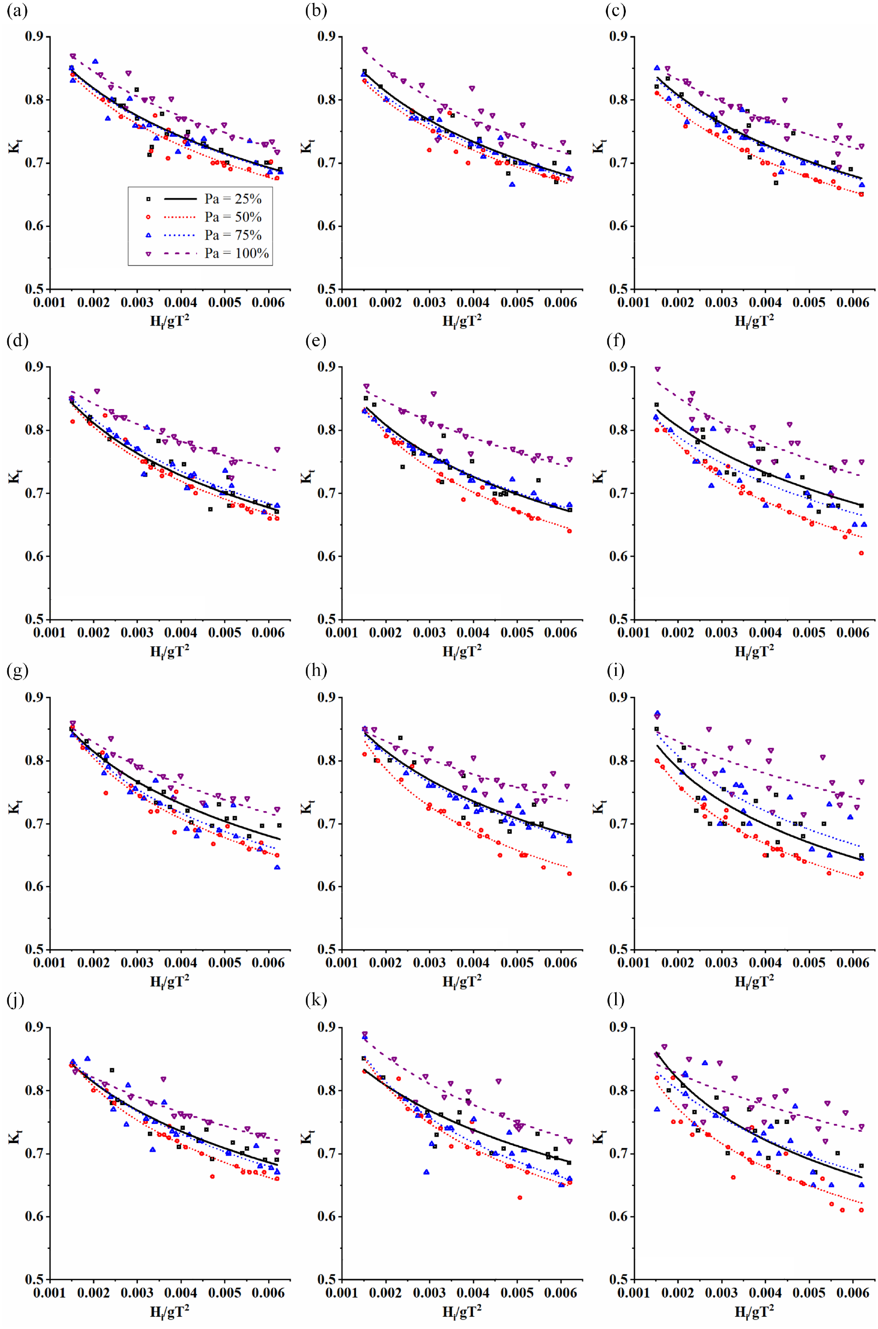
Influence of Pa on Kt for various P and S/D at h = 0.4 m (h/H = 0.769): (a) S/D = 0.15, P = 9.6%, (b) S/D = 0.15, P = 14.4%, (c) S/D = 0.15, P = 19.2%, (d) S/D = 0.20, P = 9.6%, (e) S/D = 0.20, P = 14.4%, (f) S/D = 0.20, P = 19.2%, (g) S/D = 0.25, P = 9.6%, (h) S/D = 0.25, P = 14.4%, (i) S/D = 0.25, P = 19.2%, (j) S/D = 0.30, P = 9.6%, (k) S/D = 0.30, P = 14.4% and (l) S/D = 0.30, P=19.2%.
As explained in section 2.6, the idea behind providing the perforation is to add an additional mechanism to diffuse more energy and attenuate a larger amount of waves. During the interaction between the wave crest and the CPH, a certain amount of water gets trapped inside the CPH. The trapped water flows out through the perforations in the form of smaller jets and further interacts with the incident waves causing additional turbulence. As illustrated in Figure 6, the blockage area of CPH against the wave propagation decreases with an increase in Pa. The amount of water entering the CPH is restricted due to the reduced opening in the case of Pa = 25%. Even though this amount is higher for Pa = 75% or 100%, the water easily propagates towards the lee side of the structure through the perforations without getting trapped. When the perforations are provided on 50% of the surface area (Pa = 50%), comparatively more water flows into the CPH and gets captured. This water escapes through the seaside perforations and distorts the orbital motion of incident waves, resulting in higher turbulence and energy dissipation. In this context, providing perforations on 50% of CPH is optimum in terms of wave transmission.
Influence of percentage of perforations (P)
While studying the effect of percentage perforations on the performance of CPHB, only the best performing Pa (i.e. 50%) is considered by eliminating the other cases of Pa (25%, 75% and 100%). The variation of Kt against the wave steepness for different cases of S/D is presented in Figure 10 by considering the P as a third parameter. In general, it is observed that irrespective of the size of perforations, increasing the percentage of perforation resulted in the reduction of Kt. When S/D = 0.25, the Kt obtained for P = 19.2% is about 5.7% lesser than P = 9.6%, and 4.6% lesser than P = 14.4%. In the same way, Kt is reduced by about 5.6% and 6.2% at higher wave steepness. Overall, a maximum reduction of Kt of 10.8% is achieved for P = 19.2% in comparison with P = 9.6%.
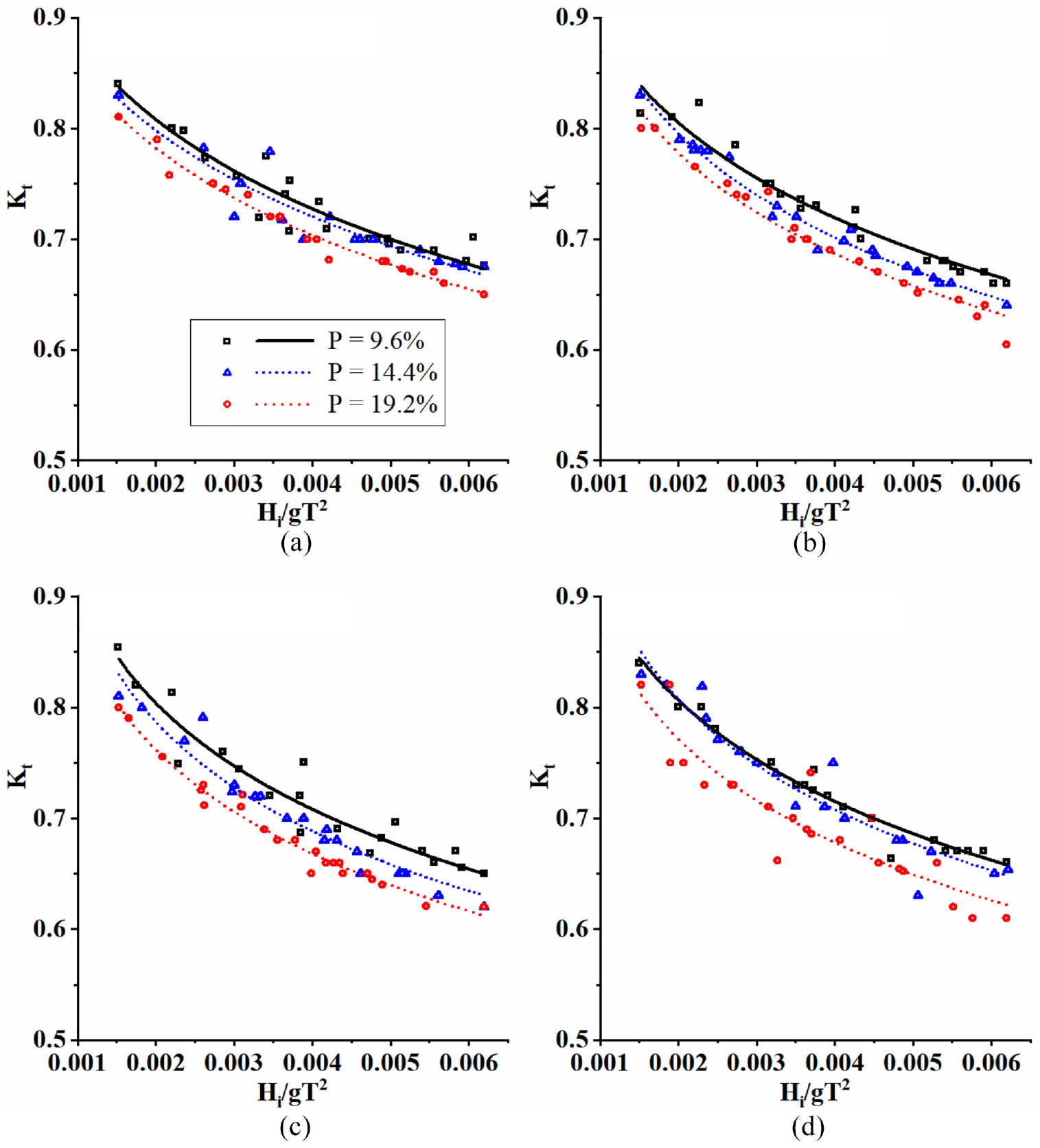
Influence of P on Kt for different S/D when Pa = 50% and h = 0.4 m (h/H = 0.769): (a) S/D = 0.15, Pa = 50%, (b) S/D = 0.20, Pa = 50%, (c) S/D = 0.25, Pa = 50% and (d) S/D = 0.30, Pa = 50%.
In the perforated CPHB structure, water enters the hollow part of the pile head through both the perforations and top. This phenomenon induces turbulence, which contributes to additional energy losses. The number of perforations on the CPH surface increases with the increasing percentage of perforations (P) under constant Pa and S/D. As the percentage of perforation increases, the amount of water entering the CPH through perforations also increases. This results in higher turbulence and energy losses leading to enhanced wave attenuation. Therefore, it can be concluded that among the considered cases, P = 19.2% is up to 10.8% more efficient in wave attenuation.
Influence of the size of perforations (S/D)
The attenuation characteristics of the perforated CPHB are evaluated under four different sizes of perforations and the same is exhibited in Figure 11(a). The different sizes of perforations studied are 0.0096, 0.0128, 0.016 and 0.0192 m which correspond to S/D ratios of 0.15, 0.20, 0.25 and 0.30, respectively. While analysing the effect of S/D, only the optimum cases of Pa and P (50% and 19.2%) are considered. The perforations provided using an S/D of 0.25 are optimum compared to the other cases studied (S/D = 0.15, 0.20 and 0.30). Referring to Figure 11(a), it is noted that irrespective of the size of perforations, the Kt values converge at lower wave steepness with a maximum variation of 2.5%. At higher wave steepness, the least Kt of 0.61 is noticed for the optimum relative pore size of 0.25. The Kt obtained for S/D = 0.25 is about 6.2%, 1.8% and 1.9% less than that of S/D = 0.15, 0.2 and 0.3 respectively.
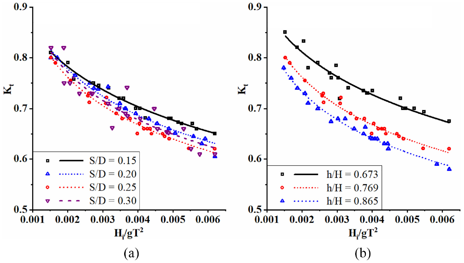
Influence of (a) S/D on Kt when Pa = 50%, P = 19.2% and h = 0.4 m (h/H = 0.769) (b) depth of water on Kt when Pa = 50%, P = 19.2% and S/D = 0.25.
Perforations with a certain percentage of perforation can be configured on CPHB, either using larger pores with a smaller number or vice versa. In the case of the smaller size of pores, the total quantity of water entering the CPH may be limited since the water needs to get contracted and enter the CPH under high pressure. During the water discharge from CPH, the smaller perforations may take a longer duration with small-sized water jets. At the same time, larger perforations empty the CPH immediately after crossing of wave crest without any cognisable jet formations. The optimum size of perforation is the one that can balance both the entry and exit mechanism of water with the optimal rate to make the structure efficient. The perforations provided with the relative size (S/D) of 0.25 may be the optimum diameter because of which a lower value of Kt is achieved. Overall, Pa = 50%, P = 19.2% with S/D = 0.25 can be inferred as the optimum configuration of CPH perforation, which resulted in a minimal Kt of 0.61 even at higher wave steepness when the depth of water is 0.4 m.
Influence of depth of water (h)
Examining the coastal protection structures at different water depths is essential because the structure may encounter different depths of water in actual sea conditions, which may arise due to base erosion, tide, and storm surge. In the present study, the optimum configuration of the perforated CPHB arrived in the previous section (section 3.1.3) is further investigated at 0.35 m (h/H = 0.673) and 0.45 m (h/H = 0.865) and the results are illustrated in Figure 11(b). Concerning Figure 11(b), it is identifiable that reducing the depth of water by 0.05 m (0.40–0.35 m) leads to an increase of Kt by about 6.2% at the gentler side and 9.6% at the steeper side of the wave. However, increasing the depth of the water by 0.05 m (0.40–0.45 m) enhanced the wave attenuation capability by 4.6% at higher wave steepness.
In the present work, wave attenuation occurs due to the combined resistance offered by the pile head and supporting circular pile. The maximum interaction between CPHB and the wave takes place when the wave crest propagates against the pile structure. The interaction of the pile head with waves is relatively higher and significant when compared to the supporting pile of the structure and also increases with the water depth. The remaining portion of the pile structure interacts with the balanced portion of the wave phenomenon. Also, as the depth of water increases, the resistance offered by the CPH against wave propagation increases due to the conical shape offering increased areas of obstruction, bringing more and more perforations on CPH into action. In this context, the following scenarios in the wave structure interaction are explained.
For a minimum water depth of 0.35 m, a maximum of 41.6 to 65% of the pile head interacts with the wave for varying wave climates. Whereas for a maximum water depth of 0.45 m, a maximum of 83.3 to 100% of the pile head interacts with the wave under varying wave climates. Further, when h = 0.35 m, about 70.8% of the CPH emerges with respect to the reference depth, which reduces to 50% at 0.40 m and 29.2% at 0.45 m. As explained before, one of the unique wave attenuation features of the CPH is the plunging of larger waves inside the hollow CPH. Wherein at 0.35 m depth of water, the plunging mechanism does not occur even for larger waves due to the higher emergence of CPH. At 0.45 m, even the gentler waves plunge into the CPH, leading to higher wave attenuation with improved energy dissipation. In brief, a minimum Kt of 0.58 is recorded at higher wave steepness for the perforated CPHB with structural configuration of D/Hmax = 0.4, Y/Hmax = 1.5 and b/D = 0.1 and perforation characteristics of Pa = 50%, P = 19.2% with S/D = 0.25 at a depth of water of 0.45 m.
Influence of wave steepness (Hi/gT2)
At coastal sites, the structure may be subjected to incident waves of different wave heights (Hi) and wave period (T). Therefore, studying the effect of the wave steepness (Hi/gT2) on the performance of the CPHB structure is beneficial in understanding the attenuation behaviour. From Figures 9 to 11, it can be identified that the wave attenuation capability of the structure is more pronounced for the steeper waves than the gentler waves by about 11.2% to 24.5%. For the optimum configuration, the Kt is reduced from 0.79 to 0.61 (22.8% reduction), where the smaller Kt corresponds to higher wave steepness and the larger Kt corresponds to lower wave steepness.
The wave steepness parameter accounts for both the height and period of the waves. The wave steepness parameter attains higher values when the wave height is larger with a shorter wavelength (smaller T) and vice versa. The steeper waves are unstable in nature, which can be easily distortable with minimal obstruction. Whereas, the gentler waves do not distort easily. Additionally, the gentler waves do not plunge into the CPH because of their shorter height of waves. Due to these reasons, the wave attenuation capability of the perforated CPHB is more pronounced against the steeper waves. The findings of the present study are in line with the results reported in the literature for conventional pile breakwater,4,16 suspended pipe breakwater 3 and pile breakwater with C-shaped suspended bars. 40
Wave reflection and dissipation characteristics (Kr and Kd)
The reflection and dissipation characteristics of the perforated CPHB are plotted with respect to the wave steepness (Hi/gT2). Figures 12 and 13 illustrates the influence of Pa on Kr and Kd at a depth of water of 0.40 m for the corresponding cases of Kt discussed in Figure 9. In general, both the Kr and Kd are found to be increasing with the increasing wave steepness. A higher value of Kr of 0.265 is obtained for the perforation configuration of Pa of 50%, P of 19.2% and S/D of 0.25, along with a maximum Kd of 0.75.
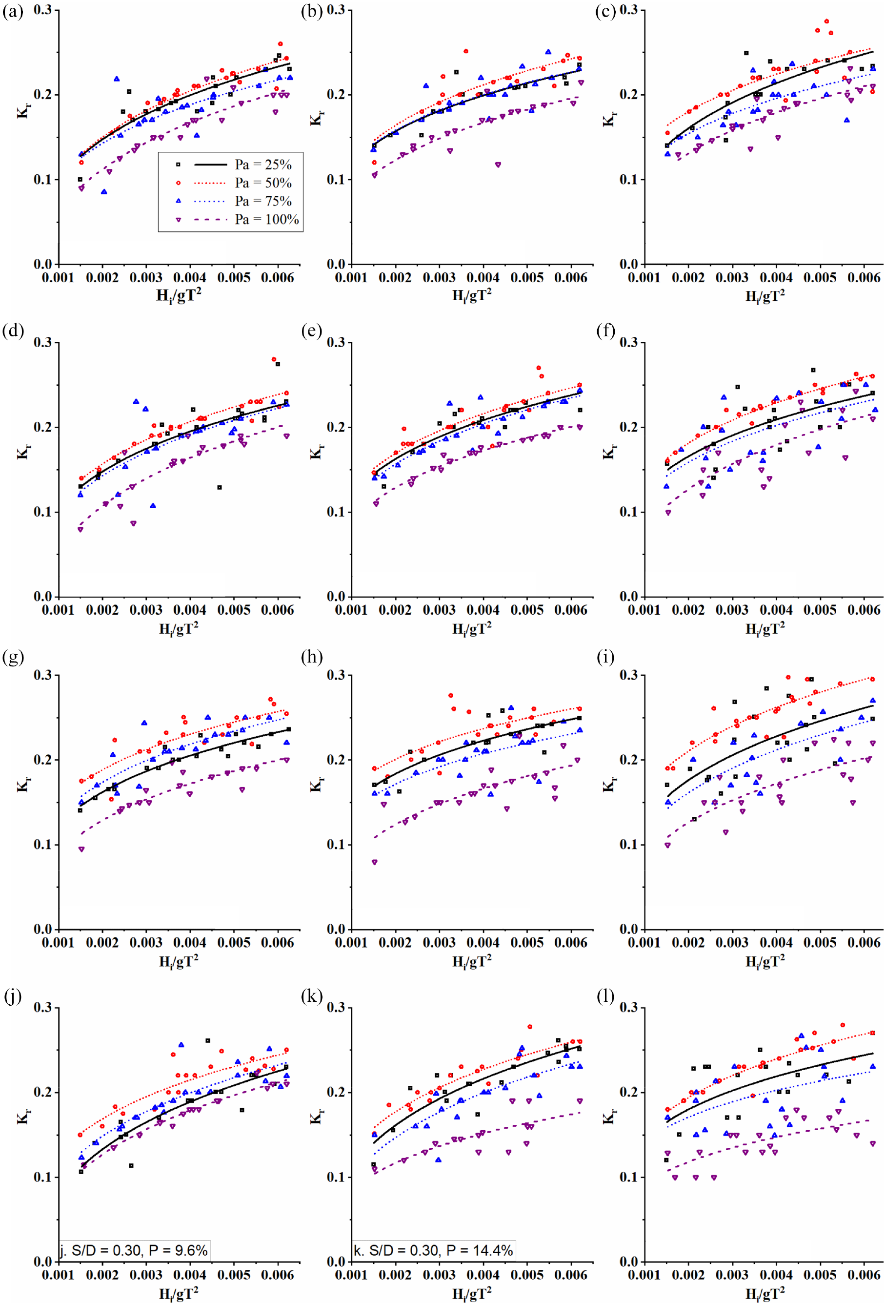
Influence of Pa on Kr for various P and S/D at h = 0.4 m (h/H = 0.769): (a) S/D = 0.15, P = 9.6%, (b) S/D = 0.15, P = 14.4%, (c) S/D = 0.15, P = 19.2%, (d) S/D = 0.20, P = 9.6%, (e) S/D = 0.20, P = 14.4%, (f) S/D = 0.20, P = 19.2%, (g) S/D = 0.25, P = 9.6%, (h) S/D = 0.25, P = 14.4%, (i) S/D = 0.25, P = 19.2%, (j) S/D = 0.30, P = 9.6%, (k) S/D = 0.30, P = 14.4%, and (l) S/D = 0.30, P = 19.2%.
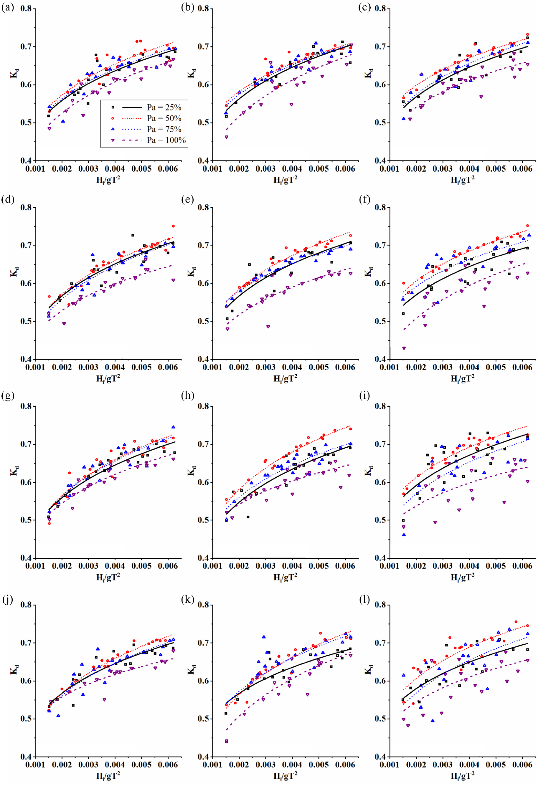
Influence of Pa on Kd for various P and S/D at h = 0.4 m (h/H = 0.769): (a) S/D = 0.15, P = 9.6%, (b) S/D = 0.15, P = 14.4%, (c) S/D = 0.15, P = 19.2%, (d) S/D = 0.20, P = 9.6%, (e) S/D = 0.20, P = 14.4%, (f) S/D = 0.20, P = 19.2%, (g) S/D = 0.25, P = 9.6%, (h) S/D = 0.25, P = 14.4%, (i) S/D = 0.25, P = 19.2%, (j) S/D = 0.30, P = 9.6%, (k) S/D = 0.30, P = 14.4%, and (l) S/D = 0.30, P = 19.2%.
The maximum variation in Kr observed is 26%, 42% and 80% when Pa is varied from 50% to 25%, 75% and 100%, respectively. In a similar way, a maximum of 7%, 11% and 21% higher Kd is recorded for Pa = 50% in comparison with 25%, 75% and 100%, respectively. When the perforation distribution Pa is 75% or 100%, part of the outflowing water from CPH passes to the lee side of the structure, posing lower reflection and dissipation. Since the lee side of the CPH is blocked in the case of Pa = 25% and 50%, the water escapes through seaside perforations. The escaping water disturbs the orbital motion of the upcoming incident waves causing higher turbulence and energy dissipation.
When Pa = 50% and S/D = 0.25, the Kr calculated for P = 19.2% is 11.5 to 14.7% higher than P = 9.6%, and 3.7 to 16% higher than P = 14.4%. For the same case, the Kd computed for P = 19.2% is 2.8 to 9.2% higher than P = 9.6%, and 1.8 to 7.4% higher than P = 14.4%. Further, for Pa = 50% and P = 19.2% combination, the Kr recorded for S/D = 0.25 is about 16%, 18.9% and 10.4% higher than S/D = 0.15, 0.20 and 0.30, respectively. For the same configuration (Pa = 50% and P = 19.2%), the Kd computed for S/D = 0.25 is 3.6%%, 0.3% and 0.6% higher than S/D = 0.15, 0.20 and 0.30, respectively.
For the optimum configured perforated CPHB, varying the depth of water from 0.40 to 0.35 m (h/H = 0.769–0.673) resulted in reduction of both Kr and Kd by 3% and 7%, respectively. Further, increasing the depth of water from 0.40 to 0.45 m (h/H = 0.673–0.865) resulted in 13.2% lower reflection and 5.7% higher wave energy dissipation. Overall it can be concluded that providing the optimum perforation configuration (Pa = 50%, P = 19.2% and S/D = 0.25) on best performing CPHB (D/Hmax = 0.4, Y/Hmax = 1.5 and b/D = 0.1) at h = 0.45 m resulted in a minimum Kt of 0.58 associated with Kr and Kd of 0.26 and 0.78, respectively.
Effect of perforations
The wave interaction between the non-perforated and the perforated CPHB with the optimum configuration at a depth of water of 0.45 m is demonstrated in Figure 14. Comparatively lower transmitted waves can be observed for the perforated case than the non-perforated CPHB. The water moving out of the CPH holes is generating additional turbulence on the seaside of the structure with higher reflection than the non-perforated CPHB. The same can be noticed in Figure 14.
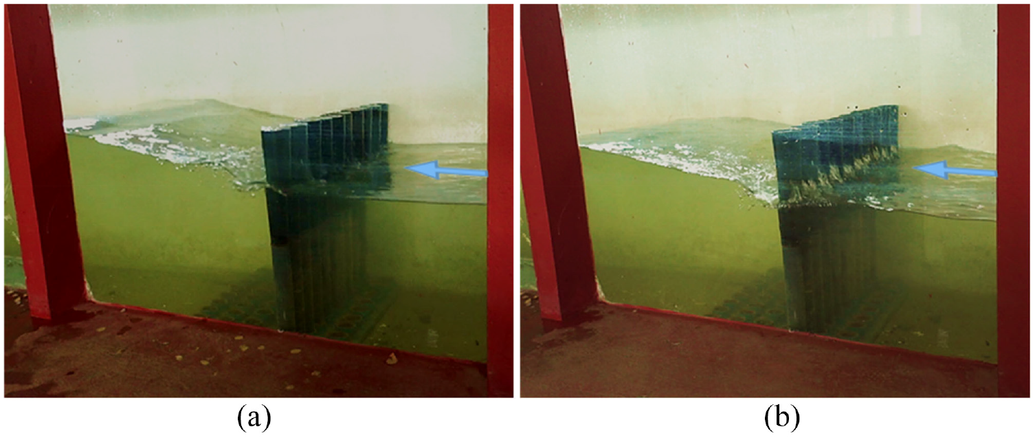
Wave interaction with the (a) non-perforated and (b) perforated CPHB (Pa = 50%, P = 19.2 and S/D = 0.25) at 0.45 m depth of water.
In order to identify the influence of perforations on the efficiency of the CPHB, the performance characteristics of the non-perforated and perforated CPHB are compared in Figure 15. Only the optimum perforated configuration (Pa = 50%, P = 19.2% and S/D = 0.25) is considered for the comparison study. The enhancement in the attenuation capability of CPHB on introducing the perforations is clearly appealing in Figures 14 and 15. The improvement in attenuation is less than 6% at lower wave steepness for all the considered depths of water. Whereas, a maximum reduction of 12.4% in Kt (0.662–0.58) is achieved at a depth of water of 0.45 m. An upsurge in both Kr and Kd is identified for the perforated structure irrespective of the depth of water. Introducing the perforations has almost doubled the Kr at 0.40 m depth of water. A maximum increment of 13% in Kd is obtained at lower steepness when h = 0.45 m.
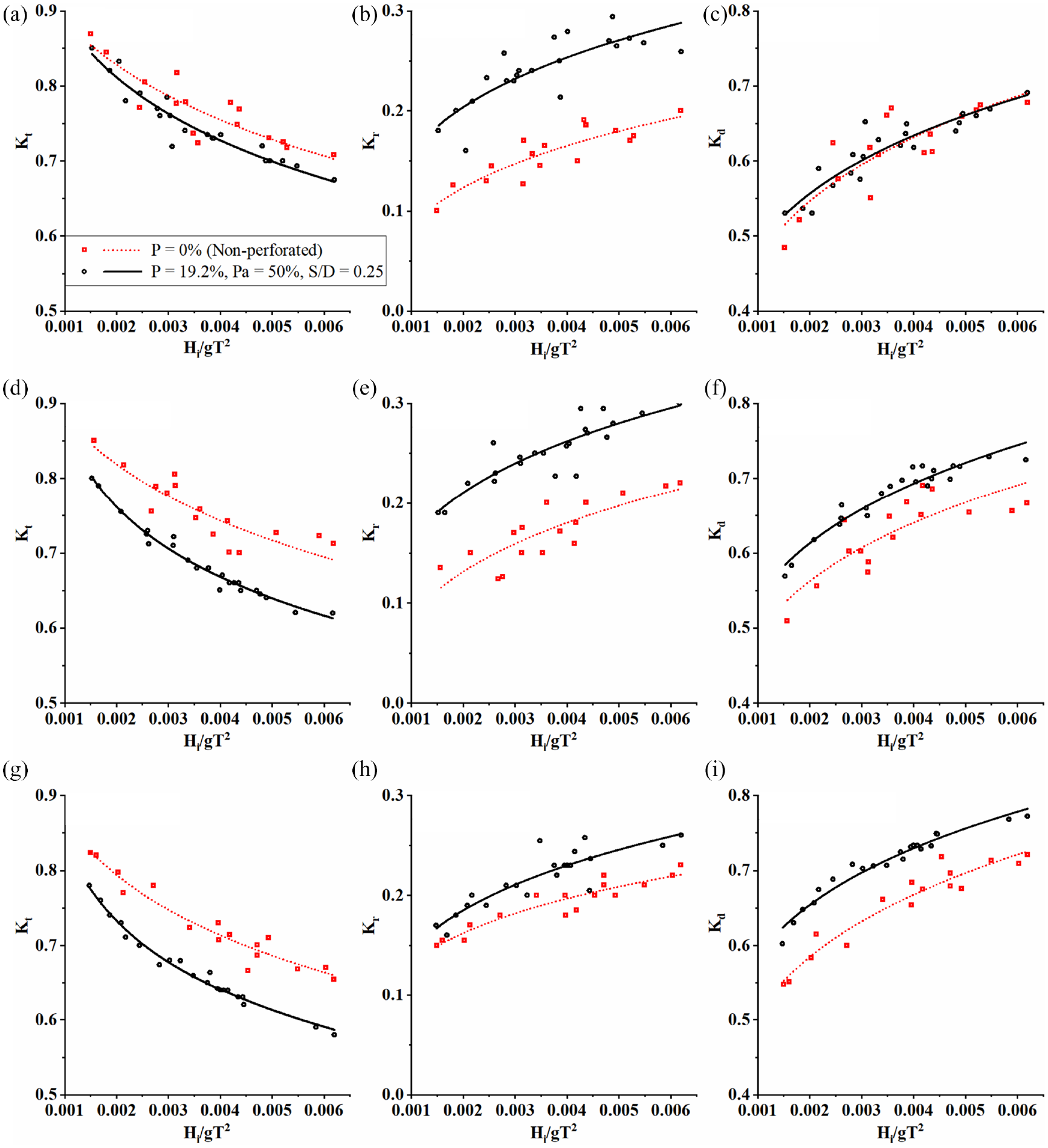
Comparison of performance between the non-perforated and perforated CPHB: (a–c) h/H = 0.673, (d–f) h/H = 0.769 and (g–i) h/H = 0.865.
The present study proved that providing the perforations on the surface of CPH is advantageous in achieving increased wave attenuation. It is also evident from the investigation that up to 12.4% reduction in Kt could be achieved by incorporating the perforations on the surface of conical pile head breakwater. The obtained outcome is well matching with the literature4,25,26,58 where, 10% to 14% lesser Kt is reported through perforations.
Comparison with other studies
Perforated hollow pile breakwater
A comparative study between the proposed CPHB structure and perforated hollow pile breakwater is carried out in order to examine the effectiveness of the proposed breakwater. Perforated hollow pile breakwater consists of an array of perforated hollow cylindrical piles where the piles have uniform diameter throughout the length, as shown in Figure 1(d). 25 The wave attenuation characteristics of the perforated hollow pile breakwater are estimated based on the theoretical approach as there are no data available in the literature corresponding to the structural configuration and test limit of the present study. Therefore, the hybrid equations developed by Suvarna et al. 42 for perforated hollow pile breakwater is adopted to extract the data. The summary of the development of the hybrid equation is provided in brief in the following paragraph for a better understanding.
The equations for Kt and Kr for the monochromatic waves flowing through non-perforated pile breakwater at a depth of water of h with an angular frequency of ω is given by Suh et al. 59
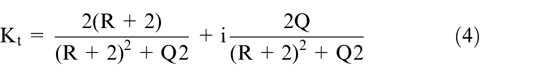
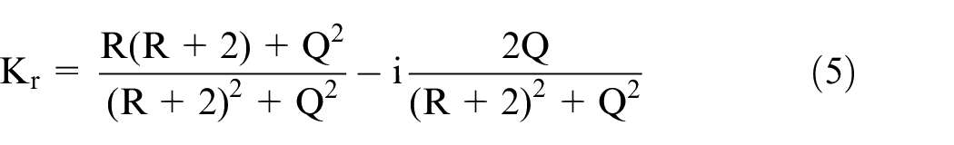
Where
l = length of jet flowing between the piles given by l = 2C and K is the wavenumber.
C is the blockage coefficient given by
Suvarna et al. 42 redefined the γp parameter empirically to make the equations suitable for perforated hollow pile breakwater as,

γ is the friction coefficient given by,
Where, XR is the reduction factor due to perforations which is given by,
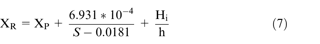
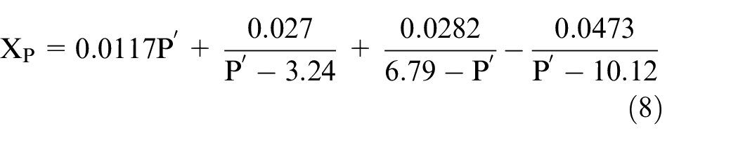
P′ is given by,
The comparative study quantifies the efficiency of the proposed structure in the present study over perforated hollow pile breakwater by keeping the same number of piles in both the cases. For the comparative analysis, the best performing perforated CPHB with a structural configuration of D/Hmax = 0.4, Y/Hmax = 1.5 and b/D = 0.1 (b0/D = 0.76, where b0 is the clear spacing between the circular supporting piles in a row), perforation of Pa = 50%, P = 19.2% and S/D = 0.25 and h = 0.45 m is considered. The attenuation parameters of the perforated hollow pile breakwater are estimated using similar perforation characteristics of CPHB, that is Pa = 50%, P = 19.2% and S/D = 0.25. The Kt, Kr and Kd of perforated CPHB and perforated hollow pile breakwater are illustrated in Figure 16.
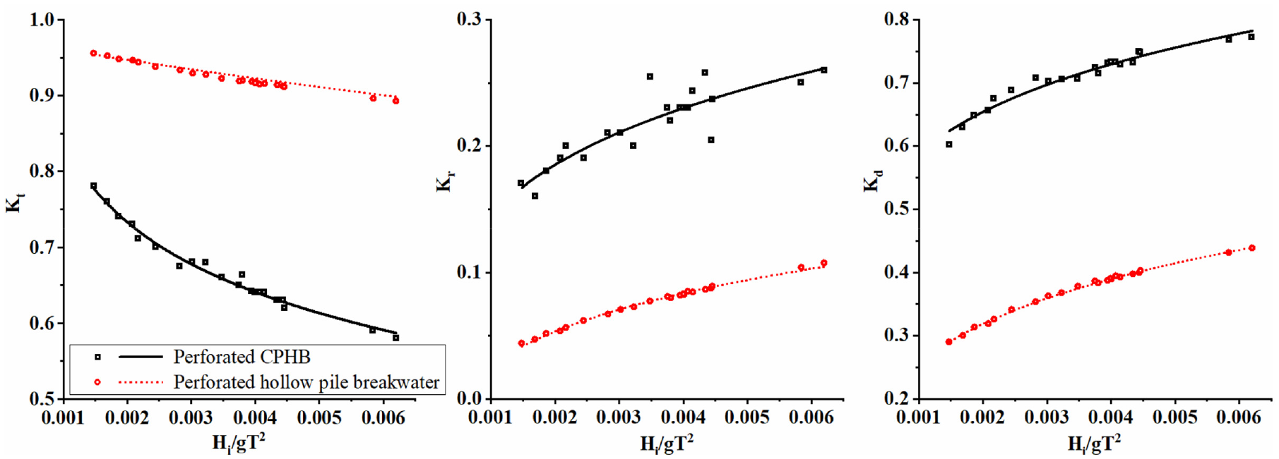
Comparison between the perforated CPHB and perforated hollow pile breakwater with the same number of piles.
The range of the Kt values observed for perforated hollow pile breakwater is between 0.96 and 0.89, whereas, for the CPHB structure, the Kt ranges from 0.78 to 0.58. About 18.7% lesser Kt is noticed at lower wave steepness for CPHB than the perforated hollow pile structure. Similarly, at higher wave steepness, about 35% lesser Kt is obtained. The Kr for perforated hollow pile breakwater ranges between 0.04 and 0.1 whereas, for the perforated CPHB, the Kr observed is between 0.17 and 0.26. At the same time, the Kd obtained for the perforated CPHB (0.62–0.78) is about double the perforated hollow pile structure (0.29–0.43). The above analysis clearly proved that the perforated CPHB is superior in performance compared to the perforated hollow pile breakwater.
Other pile breakwaters
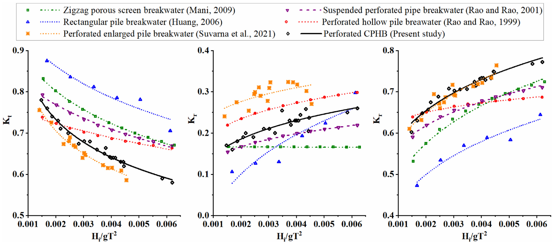
To prove the relevance of the present study, the performance characteristics of the perforated CPHB is compared against the other similar research works (Refer Figure 17) conducted on pile type of breakwaters. The results of optimum configured perforated CPHB (D/Hmax = 0.4, Y/Hmax = 1.5, b/D = 0.1, Pa = 50%, P = 19.2%, S/D = 0.25 and h = 0.45 m) is compared with the perforated hollow pile breakwater, 25 suspended perforated pipe breakwater, 26 rectangular pile breakwater, 20 zigzag porous screen breakwater 2 and perforated enlarged pile breakwater. 42
Performance comparison between perforated CPHB and other research works.
The behaviour of Kt, Kr and Kd of perforated CPHB is well matching with the other compared structures. From Figure 17, it is perceptible that a lower Kt and higher Kd are achieved than the compared pile structures. The wave attenuation capability of the present structure is in line with the perforated enlarged pile breakwater. The Kr of the perforated CPHB is higher than the suspended perforated pipe breakwater, rectangular pile breakwater and zigzag porous screen breakwater, and lesser than the perforated hollow pile breakwater and perforated enlarged pile breakwater. Considering the test conditions of the present research work, it appears that the performance of perforated CPHB structure is in line with the other structures compared.
Prediction of structure performance
Empirical equations
Predicting the performance characteristics of the CPHB quickly using empirical equations would be handy from the engineering point of view. Therefore, a set of empirical equations is proposed for the Kt and Kr of CPHB (Refer equations 9 and 10) using the Eureqa software package. The equations are obtained by feeding the experimental data to the software, where the solutions are calculated based on the data fitting technique. The experimental data of the previous study on non-perforated CPHB 49 and the present work on perforated CPHB are used as the input data. In this process, several equations are obtained and the best equations are chosen based on the coefficient of determination (R2) and relative root mean square error (RrmsE) values. The RrmsE is calculated by employing a similar method followed by Rattanapitikon 60 and Nam et al. 61 These empirical equations are applicable for both non-perforated and perforated CPHB. The equations are expressed in terms of the structural (D/Hmax, Y/Hmax, Y/2h, b/D and B/D) and perforation characteristics (Pa, P, and S/D) of CPHB along with wave parameters (Hi/gT2). The developed equations for Kt and Kr are given by,
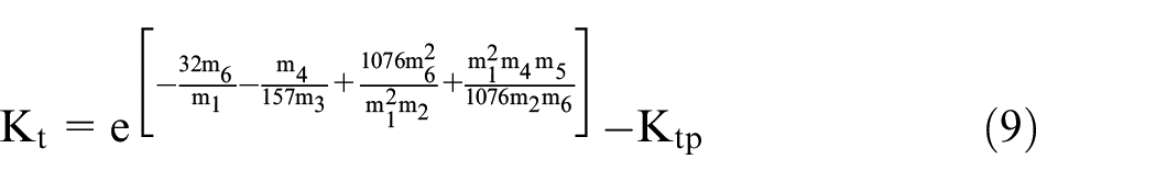
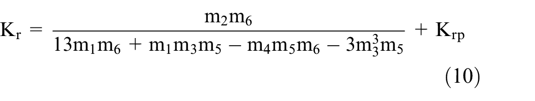
Where, m1 = D/Hmax, m2 = Y/Hmax, m3 = b/D, m4 = N + B/D, m5 = Y/2h, m6 = Hi/gT2, m7 = Pa in %, m8 = P in % and m9 = S/D. N is the number of CPHB rows spaced at a clear distance of B, which is assumed to be zero for single row case (N = 1). Ktp and Krp are the reduction factors of wave transmission and reflection coefficients respectively, which are given by,
Validation of equations
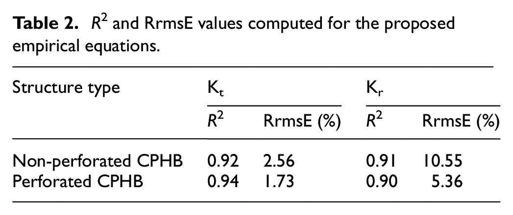
The experimental data published on non-perforated CPHB 49 is considered to validate the potential of the non-perforated empirical equation and present experimental results are used for the perforated case. The validation of empirical equation results with the experimental data is presented in Figures 18 and 19 for non-perforated and perforated CPHB, respectively. The R2 and RrmsE values computed for the Kt and Kr of proposed empirical equations are listed in Table 2. A reasonably good agreement is obtained between the predicted values and experimental data for both non-perforated and perforated CPHB. Hence, it can be stated that the proposed empirical equations are reliable in predicting the Kt and Kr of both non-perforated and perforated CPHB within the limits of test conditions.
Validation of empirical predictions with the experimental data of non-perforated CPHB.
Validation of empirical predictions with the experimental data of perforated CPHB.
R 2 and RrmsE values computed for the proposed empirical equations.
Conclusions
The following conclusions are drawn based on the present research work. In general, the transmission coefficient of perforated CPHB decreases with an increase in wave steepness whereas, the reflection and dissipation coefficients follow the opposite trend. The distribution of perforations (Pa) on CPH, percentage of perforations (P) and the size of perforations (S/D) play a significant role in influencing the performance characteristics of the structure.
The wave attenuation capability of the proposed perforated CPHB structure appears to be optimum when the Pa = 50%, P = 19.2% and S/D = 0.25. A minimum Kt of 0.58 associated with Kr of 0.26 and Kd of 0.78 is realised for the optimum configured perforated CPHB at a water depth of 0.45 m. The study indicates that the perforated CPHB is efficient in wave attenuation than the non-perforated CPHB by up to 12.4%. The comparative study between the perforated CPHB and perforated hollow pile breakwater revealed that the former structure is about 18% to 35% more effective in wave attenuation than the latter. Further, the empirical equations developed predict the performance characteristics of both non-perforated and perforated CPHBs with good reliability. Overall, it can be concluded that the present innovative pile head breakwater structure may be considered as one of the options as a shore protection measure.
Footnotes
Appendix
Acknowledgements
The authors gratefully acknowledge the Department of Water Resources and Ocean Engineering for providing the opportunity to conduct the research work in the wave mechanics laboratory constructed under the DST-FIST programme (Sanction order No. SR/FST/ETI-360/2014). The authors also acknowledge the role of the Centre for System Design (CSD), NITK Surathkal, in providing assistance in the 3D printing of test models.
Declaration of conflicting interests
The author(s) declared no potential conflicts of interest with respect to the research, authorship, and/or publication of this article.
Funding
The author(s) disclosed receipt of the following financial support for the research, authorship, and/or publication of this article: This research work was financially supported by MHRD, Govt. of India under the SPARC scheme (Order No. SPARC/2018-2019/P262/SL).