
Abstract
Today’s CI engines are subject to strict regulations of pollutant emissions and ambitious fuel consumption targets. Therefore, the interaction between the engine and the exhaust aftertreatment system (ATS) has become increasingly important. Numerous studies have shown that a variable valve train (VVT) improves the interaction between engine and ATS. However, most of these studies either quantify the advantage on a specific engine or only present complex CFD models, such that the results are not easily transferable to different engines. Thus, engine manufacturers cannot directly use these results to assess the advantage of various VVT strategies for their engines. In this paper, we propose a cycle-discrete cylinder model based on first principles which allows to simulate various VVT strategies. In contrast to present methods based on CFD, the proposed cylinder model can be realized with the equations presented. Furthermore, the model is identified with measurement data of an engine without a VVT. A separate engine, which is retrofitted with a fully VVT, is used to validate the proposed modeling approach. Using the identified model in combination with a mean-value model of the air path, we are able to simulate the effects of early intake valve closing, early exhaust valve opening, and cylinder deactivation for a complete CI engine that has no VVT installed. The model is then used to highlight the advantage of a VVT for two scenarios at part-load operation. At cold start, where the temperature of the ATS must be increased quickly, variable valve timing achieves higher enthalpy flows to the ATS while also lowering engine-out NOx emissions when compared to a standard engine strategy. If the ATS is at the operating temperature, cylinder deactivation achieves significantly higher enthalpy flows which prevents the ATS from cooling down. In addition, cylinder deactivation also lowers fuel consumption and engine-out NOx emissions.
Keywords
Introduction
Numerous variable valve train (VVT) systems for CI engines that feature various capabilities in terms of valve timing, valve lift, and actuation speed are presented in literature. Since most of the advantages are achieved by using variable valve timing and cylinder deactivation, we will limit our review to this specific case. The resulting effects are based on steady-state engine results and can be categorized into three categories. First, by adapting the valve timings for each engine speed, a VVT optimizes the cylinder gas exchange with the air path. This can be used to increase low-speed engine torque or to further increase efficiency for various engine speeds.1–3 In addition, a VVT can also be used for engine braking.1,4 Second, numerous authors assess the trade-off between engine efficiency and engine-out emissions. The most prominent example is the use of early intake valve closing (IVC), which improves engine brake efficiency due to reduced pumping loss.5–8 The early IVC strategy is also known as Miller cycle. If the boost pressure is not increased, early IVC results in higher soot emissions due to a decrease in engine mass flow. In combination with a highly efficient turbo-charging system and increased boost pressure, the Miller cycle improves efficiency over a wide load range without increasing soot emissions.9,10 In addition, the Miller cycle also lowers engine-out NOx emissions,2,5,9,11 which positively affect the inherent efficiency-NOx trade-off of CI engines. Third, more recent publications focus on the interaction of a CI engine with a VVT and its exhaust aftertreatment system (ATS). In today’s CI engines, the ATS plays a key role in the reduction of pollutant emissions. With regard to NOx emissions, SCR catalysts only work if the catalyst is operated in a narrow temperature window of
To the best of the authors’ knowledge no simple methodology exists that allows to quantify the advantages of including a VVT on an existing engine layout. Most experimental publications2,3,6,7,17,20–22,24–28 assess the advantages gained on a specific engine, which are not directly transferable to other engines. Other publications2,5,11,19 use complex CFD simulation tools that require proprietary software and in-depth knowledge of fluid dynamics. Hence, engine manufacturers cannot easily assess if the advantages to be gained by retrofitting their current engine with a VVT is worth the increased effort. In addition, the results are often not discussed for the complete engine system which also features the air path and ATS. If no ATS is directly included in the analysis, the results must be discussed in the context of the triple trade-off of efficiency, NOx emissions, and exhaust enthalpy.
Our contribution is threefold: First, we propose a cycle-discrete model based on first principles that describes the charge, combustion, and discharge of an engine cylinder with negative valve overlap. We integrate the cylinder model into an existing air path model 39 to simulate the complete engine as a mean-value model. Second, the model proposed is able to simulate various VVT strategies, such as early IVC (Miller cycle), early EVO, and cylinder deactivation. We assume a VVT system that can change valve timing and cylinder deactivation on a cycle-to-cycle basis. The model is identified with standard valve timing only and allows for the extrapolation of the VVT strategies mentioned. In contrast to existing approaches, the cylinder models proposed can be implemented using the presented equations without the need of any additional simulation tools. The models proposed, which are used for the simulation of various VVT strategies, have been validated on a separate engine retrofitted with a fully variable valve train. Figure 1 shows an overview of the method proposed. Finally, we demonstrate the advantages of various VVT strategies for a CI engine at part-load and steady-state operation. The presented case study demonstrates how optimal solutions are obtained systematically by studying the Pareto-optimal trade-off curves for fuel consumption, engine-out NOx emissions, and enthalpy provided to the ATS. We thereby show that the cylinder models proposed can be used to easily quantify the benefits of various VVT-strategies.
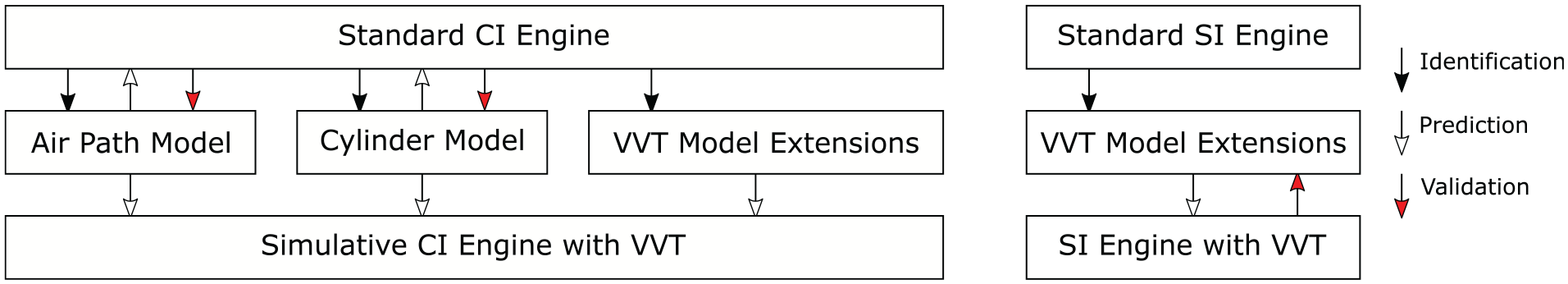
An overview of the proposed method. We use measurements of a CI engine without a VVT to create a simulative model of the same engine with various VVT capabilities. The proposed identification of the VVT model extensions are validated on an engine which has been retrofitted with a VVT.
This paper is structured as follows: Section 2 introduces the experimental setup. In Section 3 the discrete-event cylinder model is presented together with the model extensions that allow for the simulation of early IVC, early EVO, and cylinder deactivation. Section 4 then shows the cylinder model identified and the validation of the model extensions proposed on a separate engine retrofitted with a VVT. Finally, Section 5 shows a simulative case study for a CI engine with a VVT and the improvements which result in terms of Pareto-optimal solutions of fuel consumption, engine-out NOx emissions, and exhaust enthalpy.
Experimental setup
The engine of interest, which has no VVT installed, is a Volkswagen Diesel engine of the EA189 engine-family. The engine system includes a turbocharger (TC) with a variable turbine geometry (VTG), a high-pressure EGR path (HP EGR), and a common-rail injection system. Furthermore, the engine is retrofitted with a low-pressure EGR path (LP EGR). Figure 2 shows an overview of the engine, which will be denoted as engine A. The engine operating point is defined by the engine torque

where
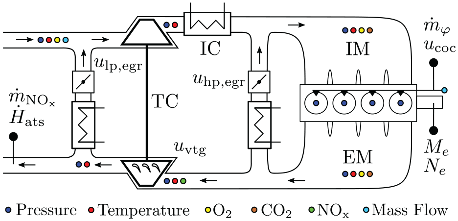
Layout of engine A. Only the most relevant sensors are shown.
Figure 3 shows a detailed overview of the test bench setup for engine A. A rapid control prototyping system (RCP) from dSpace is used to control the engine and record all signals. The engine control software is developed completely in-house. An FPGA-board on the RCP allows for a fast evaluation of the cylinder pressure signals, which can be used for a cycle-to-cycle control of the fuel injection. The oxygen concentration is measured with standard wide-band lambda-sensors, whereas NOx is measured with a smart NOx lambda-sensor. To measure the
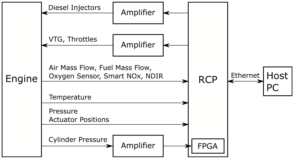
Testbench setup for engine A.
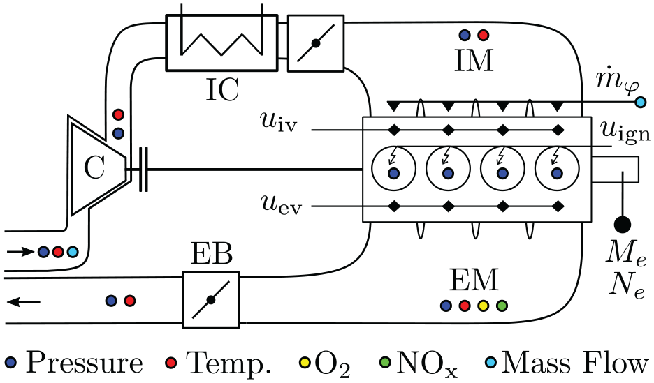
Layout of engine B. The exhaust brake (EB) can be used to increase the exhaust manifold pressure which is used to simulate the back pressure caused by a turbocharger.
Process model
The process model consists of two parts: the air-path model and the cylinder model. Figure 5 shows an overview of the various inputs and outputs of these models. In this section, we derive a cylinder process model that enables the simulation of the VVT strategies mentioned above. The model is based on first principles and features regression functions which are determined by experiments. We first derive a model with standard valve timing only and then present the extensions to model variable valve timing and cylinder deactivation. The air path is modeled by an existing mean-value model which has already been validated. 39 Other forms of air-path models can be used as long as the interactions to the cylinder model remain unchanged. For the layout of engine A, previous analyses showed no advantages for a steady-state optimization of HP EGR when compared to LP EGR. 39 Therefore, HP EGR is neglected in the analysis below.
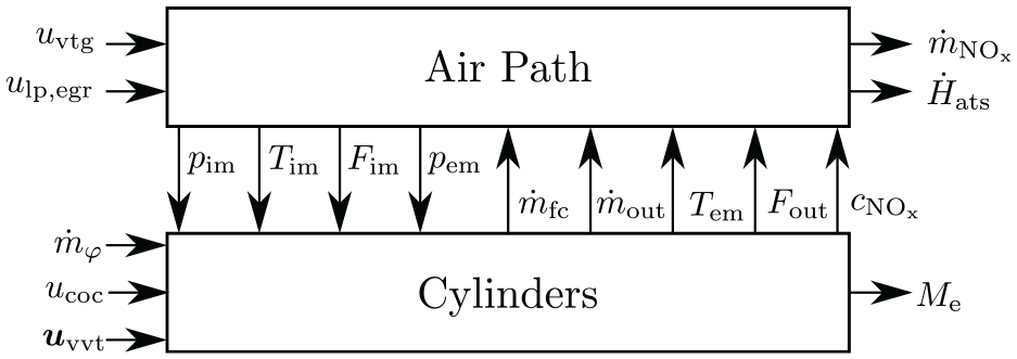
The process model consists of the air path model and the cylinder model. The various VVT inputs are summarized by
Basic definitions
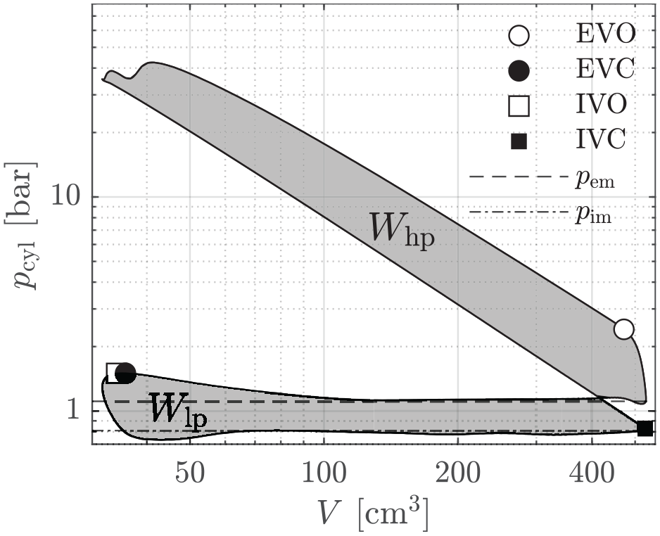
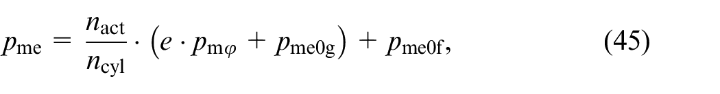
The Willans approximation links the brake mean effective pressure

The term
where
where

where
where

In the text below, the term “pumping loss” will be used interchangeably for
Exemplary
Figure 7 shows the proposed valve-area model. The effective valve area
and are assumed not to change the overall shape of
where
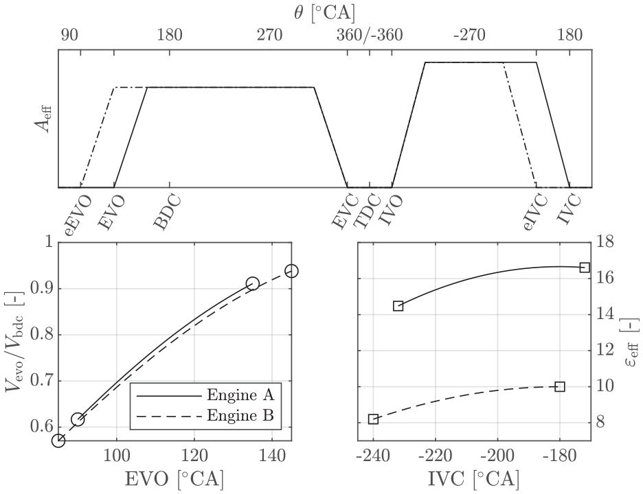
The top plot shows the effective valve areas for intake valve and exhaust valve with respect to valve timing. No valve overlap is considered. The bottom plots show the range of valve timings investigated for each engine, respectively.
Cylinder model
The cylinder is represented by a discrete-event model, which is based on the cycle-to-cycle dynamics of the residual cylinder charge at EVC. The discrete model itself is divided into different stages which track the evolution of the cylinder states

where
The following notation is used for the discrete-event cycle

whereas the subscripts describe a stage of the cylinder model, for example, for EVC:

The cylinder model thus reads as follows:
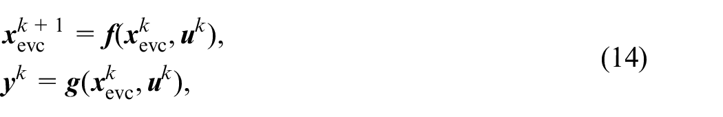
where the states of the discrete-event model are the cylinder states at EVC at cycle
The input to the process model is defined as

which consists of the injected fuel mass per cylinder per cycle

which represents the variable valve timings (8) and the number of active cylinders
The parameter

This model implies that the cylinder outputs
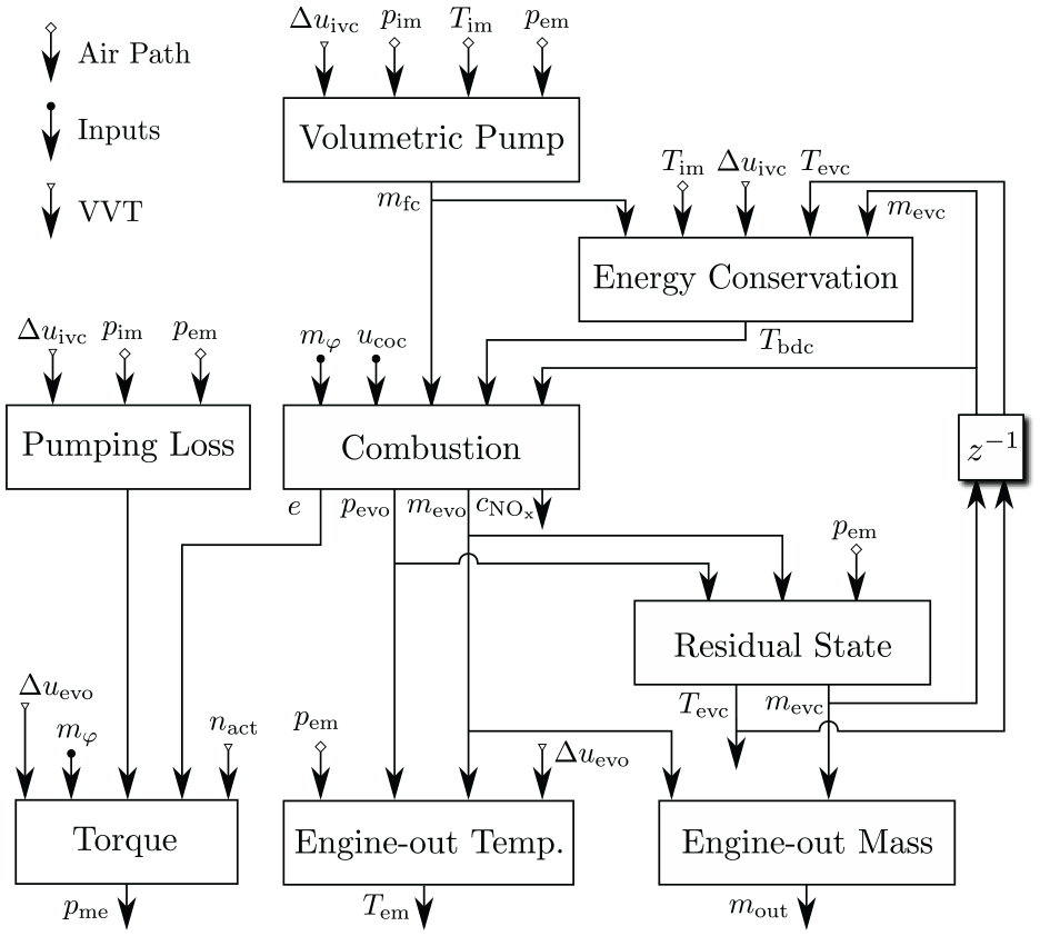
Causality diagram for the discrete cylinder model. For simplicity, the variable oxygen mass fraction
The diagram is a simplification of the complete cylinder model and only shows the most important submodels which are affected by the VVT strategies mentioned. The discrete-event model is now derived on the basis of the various stages during an engine cycle which are shown in Figure 9. For the standard model derivation the VVT inputs are omitted. The first stage of the model starts with EVC, which defines the residual gas charge
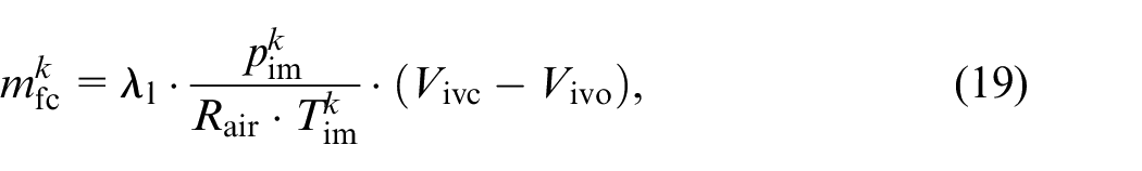
with the volumetric efficiency defined as
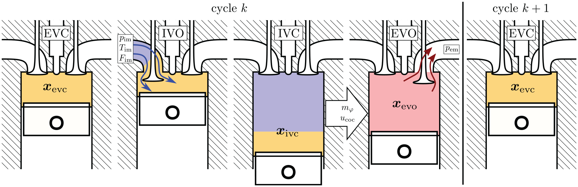
Overview of the most important stages of the discrete cylinder model. The states
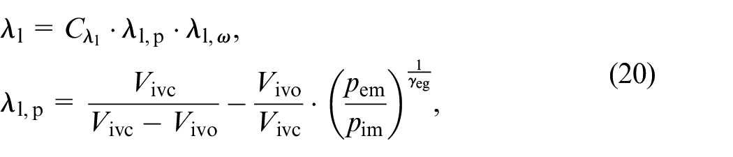
where
where
and a correction term
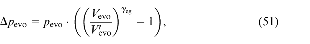
Since

where
The variable
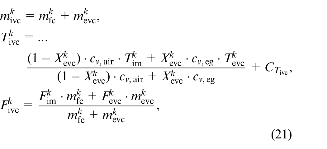
Assuming a pressure equalization at EVC with the exhaust manifold, the residual mass for the next cycle is obtained using the equation of state
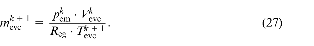
Since the oxygen mass fraction from EVO to EVC does not change either the state update is obtained by combining all of the above equations into
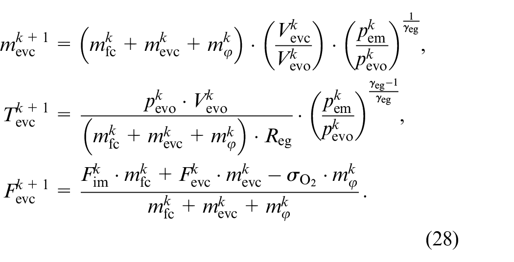
Equations (28) describe the discrete-event state update of equation (14). A detailed derivation is shown in Appendix A.3. The torque

and the friction loss and pumping loss
The engine-out NOx emissions

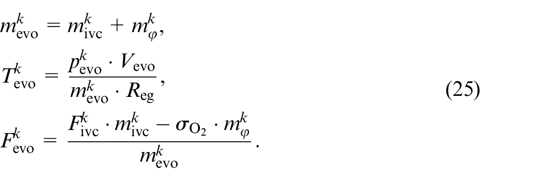
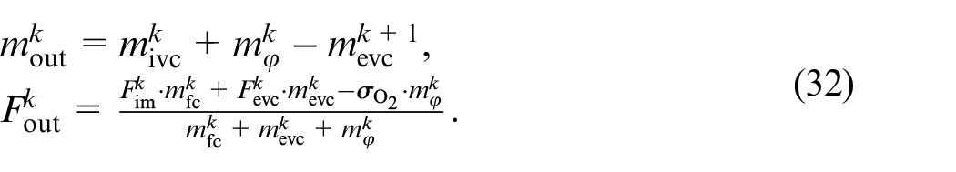
whereas the engine-out mass and oxygen gas mass fraction are obtained by the difference of mass present in the cylinder at EVO and at EVC
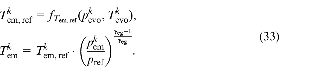
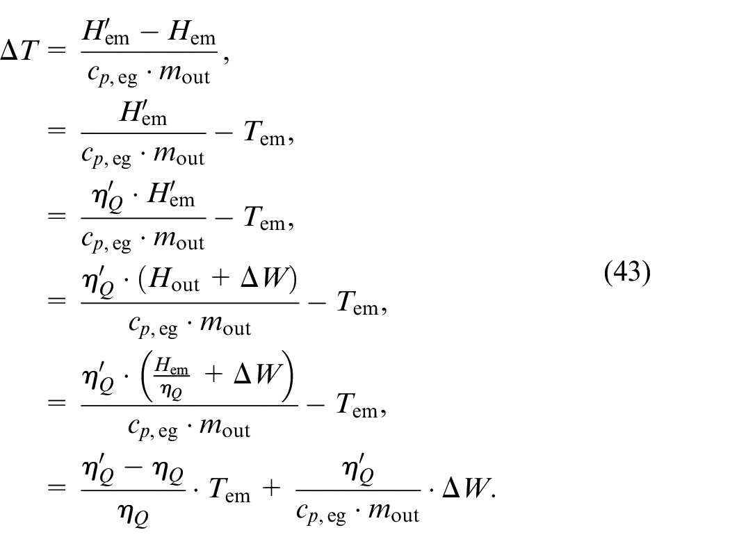
For the exhaust manifold temperature
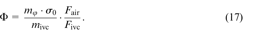
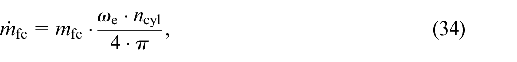
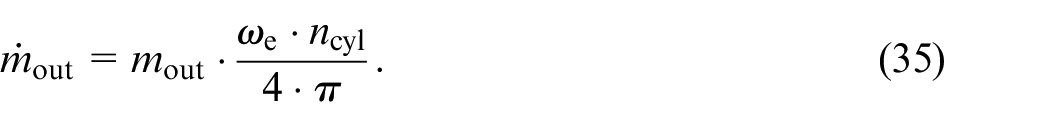
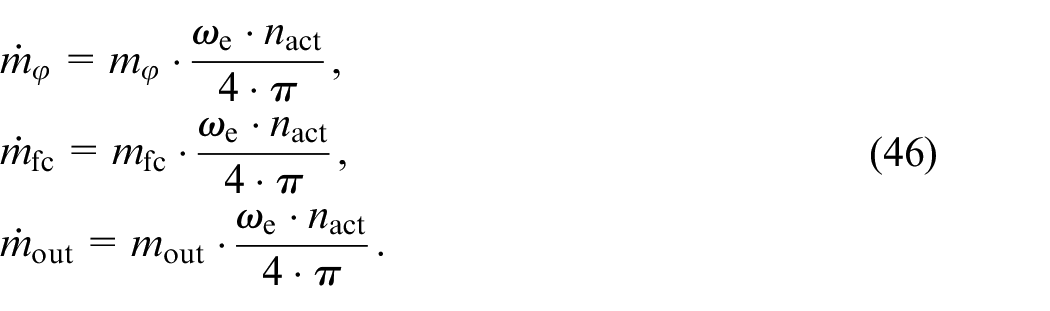
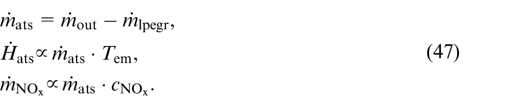
Finally, we obtain a formulation of the mass flows for use in the mean-value air-path model by the following factor:
For the model presented, we need to experimentally identify
Extensions for VVT
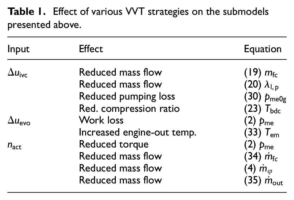
The Miller cycle (early IVC), early EVO, and cylinder deactivation are yet to be included in the cylinder model presented. Table 1 shows the effects of these VVT strategies. For the identification of the model, only measurements with standard valve timing are required.
Effect of various VVT strategies on the submodels presented above.
Miller cycle
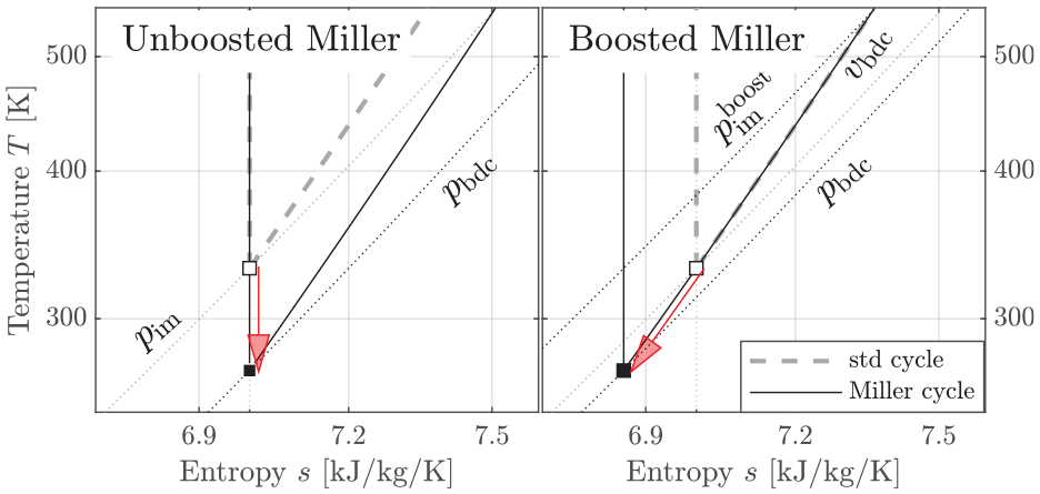
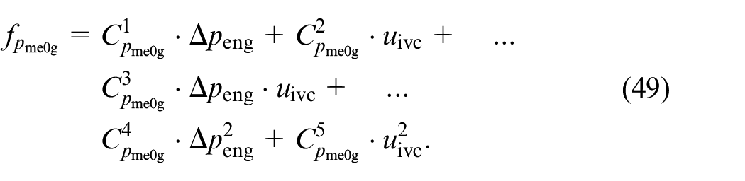
The three main effects of the Miller cycle are a reduction in fresh charge, a reduction in pumping loss, and a reduced compression ratio. The effect of an early IVC on the fresh charge is already included in the formulation of equations (19) and (20). Hence, no additional parameters are needed. Figure 10 shows the effect of an early IVC on the gas exchange. The altered pumping loss can de derived from the
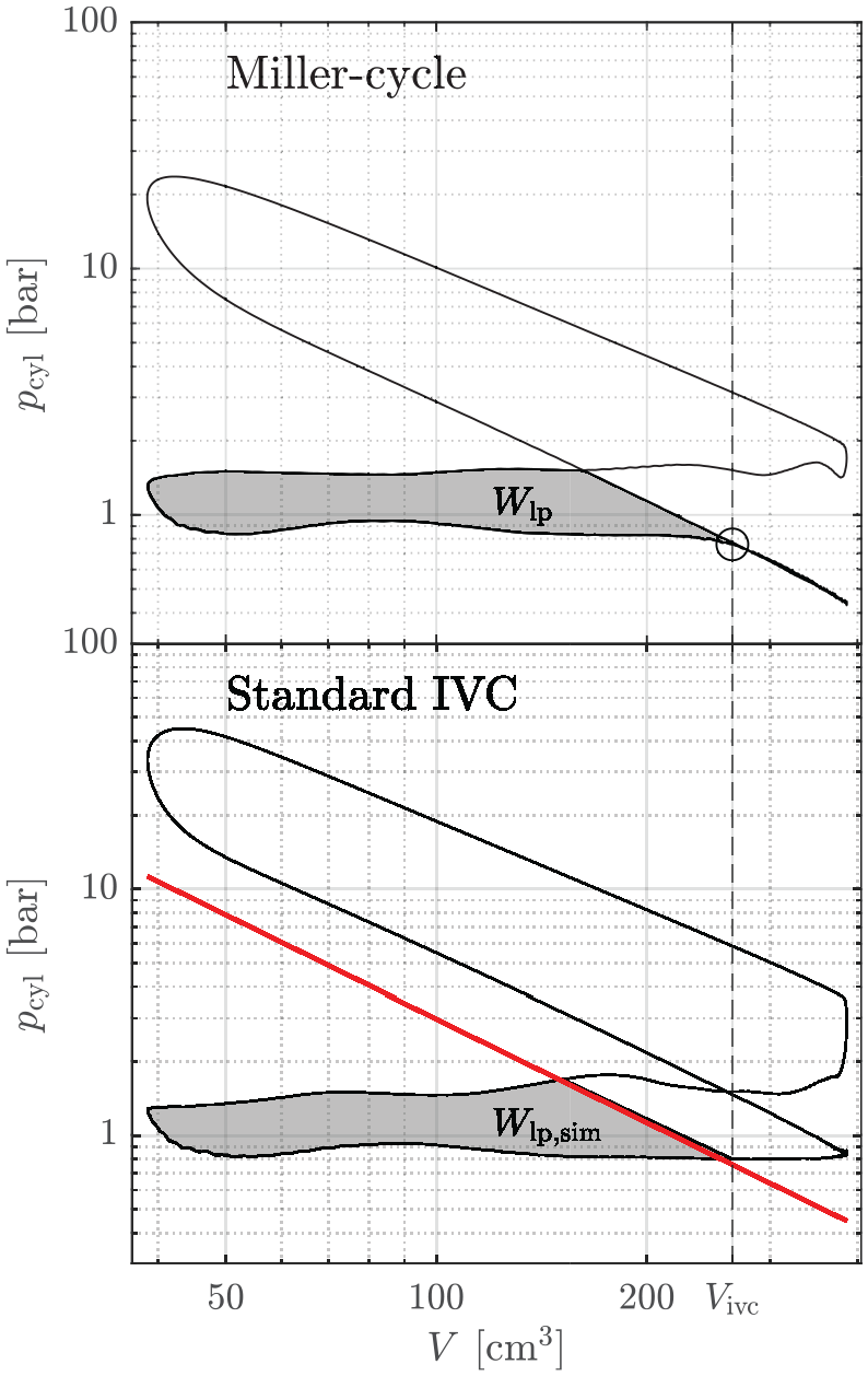
The top plot shows the
Zoomed-in
Early EVO
Two main effects must be modeled for early EVO: a loss of indicated work and an increase in exhaust temperature. Both are caused by the loss of work potential of the expanding gases inside the cylinder. Figure 12 shows two
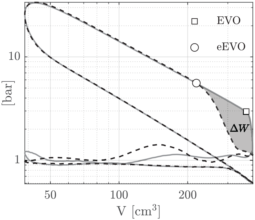
The dashed line shows the cylinder pressure
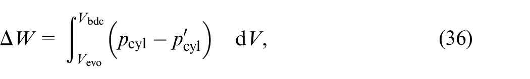
The work loss compared to standard EVO is calculated by
with which we obtain a decrease in load by
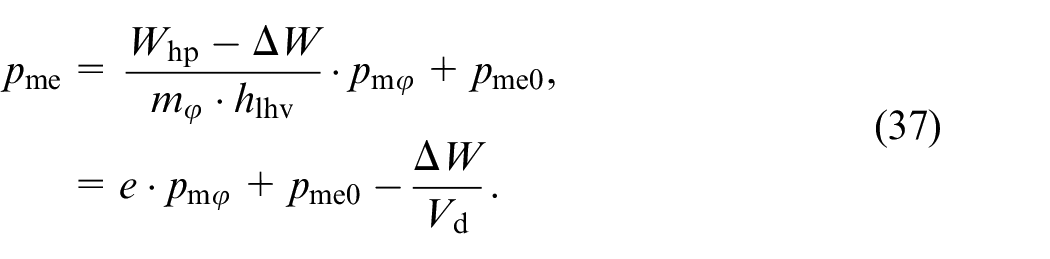
Figure 13 depicts the various control volumes of the exhaust path that are required to derive a model for the increase in temperature. In addition, we need to make the following assumptions for the derivation: an early EVO does not change
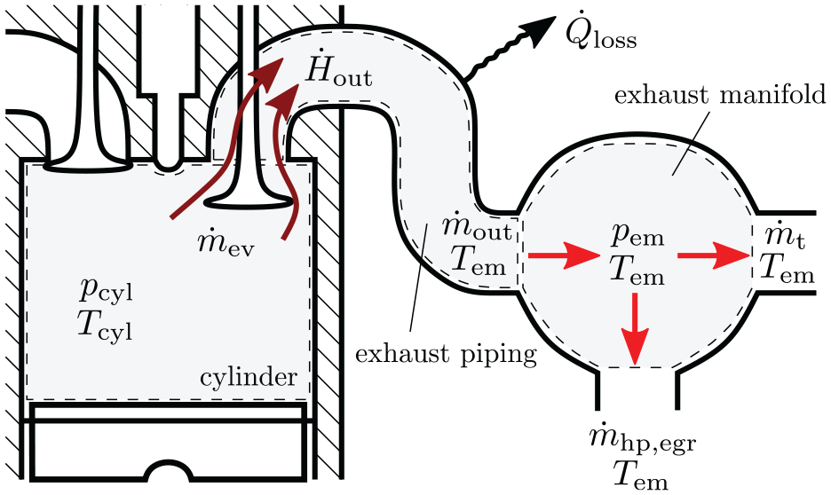
Model of the exhaust path used for the derivation of the enthalpy increase due to early EVO. The model uses three different control volumes: cylinder, exhaust piping, and exhaust manifold. The control volumes are indicated by dashed lines.
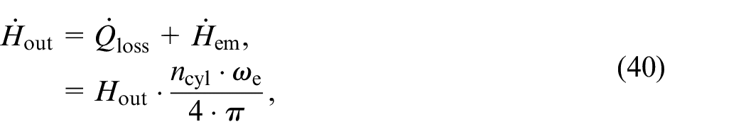
First, we define the enthalpy that enters the exhaust manifold:

where

In order to find an expression for
where
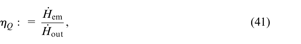
where

Using the above equations for a single cylinder and on a cycle-discrete basis, we conclude that
If
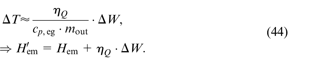
Once we know
Cylinder deactivation
The deactivation of a cylinder is defined as an operation with closed valves. The deactivated cylinder is assumed to be a perfect gas spring without any additional losses, as shown in Refs.44,45 In addition, we assume no boost pressure from the turbocharger during cylinder deactivation. The torque generation is described by
where
The deactivation thus changes the mass flow of NOx and the enthalpy flow to the aftertreatment system, as follows:
Model identification and validation
In this section, we analyze the models proposed in Section 3. First, we use measurement data obtained from engine A to demonstrate the validity of the proposed cylinder model. We then integrate the cylinder model into an existing air path model to validate the quantities of interest, namely
Engine model
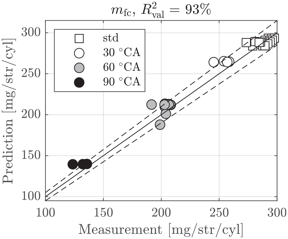
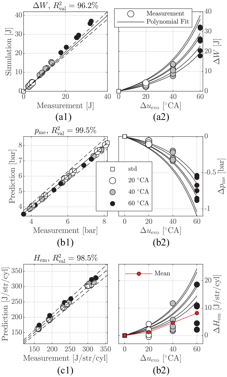
The cylinder model derived in Section 3 is based on functions and constants that need to be experimentally identified. Using regression analysis, we propose the following models:
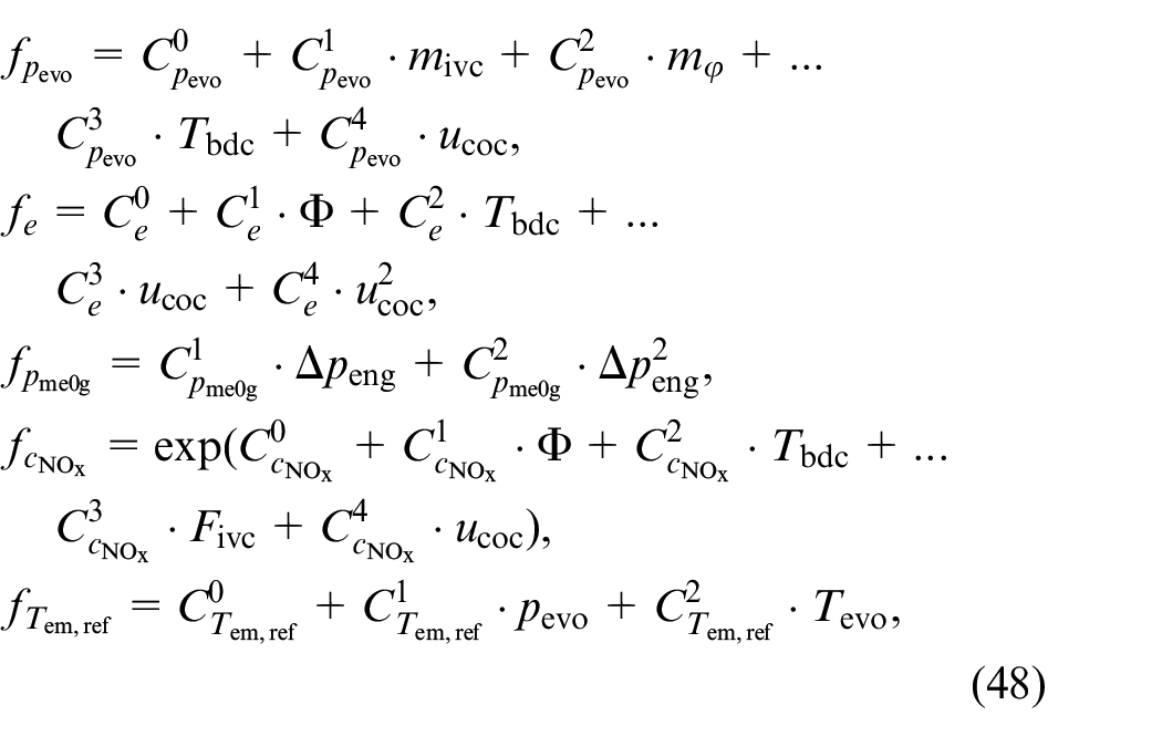
where
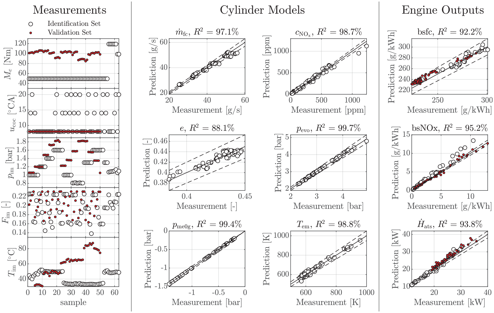
Identified models for the engine A at 2000 rpm. The left column of plots show the measurements used for identification and validation. The middle plots show the identified cylinder models. The right column of plots show the results of the complete model including the air path. In all the plots, the dashed lines denote an error margin of 5%.
Miller cycle
The three effects of early IVC, which are highlighted in Table 1 and in Section 3.3.1, are validated with measurements from the engine B. First, we validate the proposed model for the fresh charge. For the identification of the model, we only use measurements with standard IVC, that is, at BDC. Using the model identified, we predict the reduced fresh charge. Figure 15 shows the results. As expected, the fresh charge is reduced proportionally to the reduced displacement volume due to early IVC. Second, we validate the proposed approach to obtain a prediction for the reduced pumping loss
Data of engine B. Validation of the reduced cylinder fresh charge
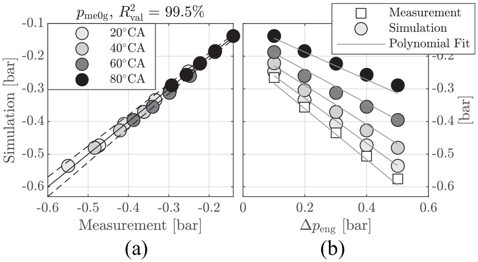
Data of engine B. Plot (a) compares the simulation of
Finally, the reduced effective compression ratio
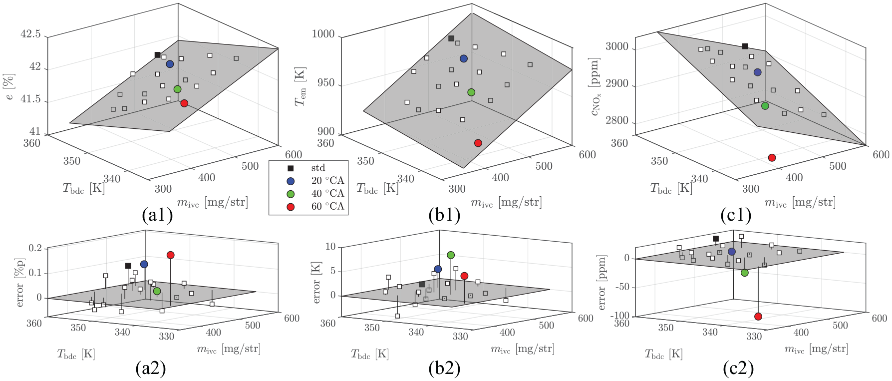
Data of engine B. The top plots show the outputs efficiency
Early EVO
Since no measurements with early EVO are available for the engine A, we must rely on simulations of the cylinder pressure
The variable
where again
Data of engine B. Validation of the work loss
Cylinder deactivation
We demonstrate the validity of the proposed cylinder deactivation model with measurements from the engine B. For standard stoichiometric operation without boost pressure, the fuel mass per cylinder defines all quantities, namely
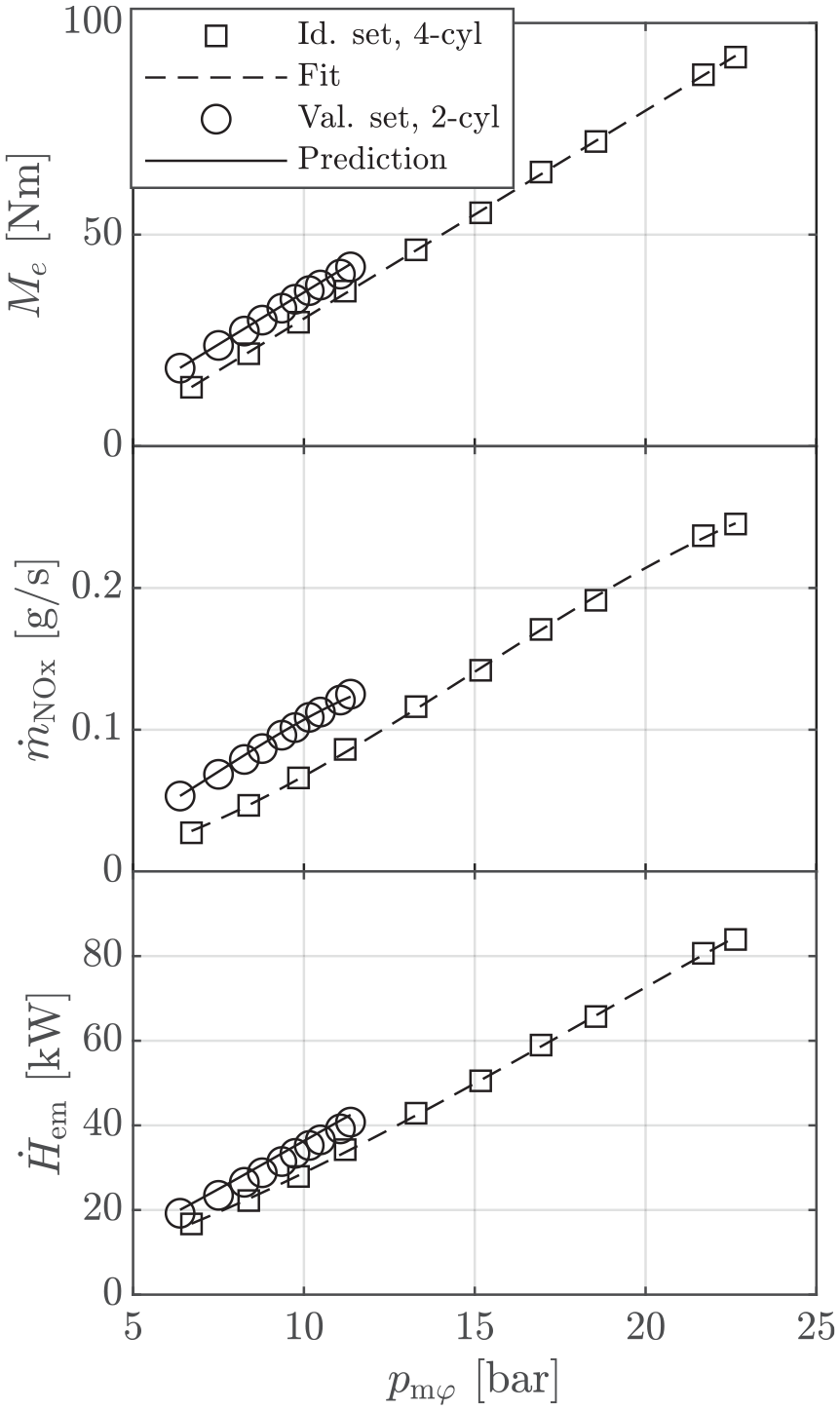
Data of engine B. Validation of the proposed cylinder deactivation model. The markers denote measurements, whereas lines denote the predictions of the fitted model. The identification set consists of measurements with all 4 cylinders active, while the validation set consists of engine an operation with only 2 active cylinders.
Case study
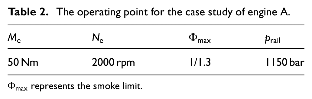
We have demonstrated that the cylinder model allows for the simulation of various VVT strategies. Since the cylinder model can be identified with standard valve timing only, there is no need to actually install a VVT. Hence, the model approach presented enables a first evaluation of the advantages of a CI engine with a VVT. As an example, we analyze the effects of a VVT installed on engine A and the impact on the Pareto-optimal trade-off curves for both warm-up operation and stay-warm operation at part load for a single engine operating point. To evaluate the effects on the outputs of interest, we use the complete model including the air path. The operating point is defined in Table 2. Figure 20, which can be found at the end of the paper, shows the results for warm-up operation, that is, when
The operating point for the case study of engine A.
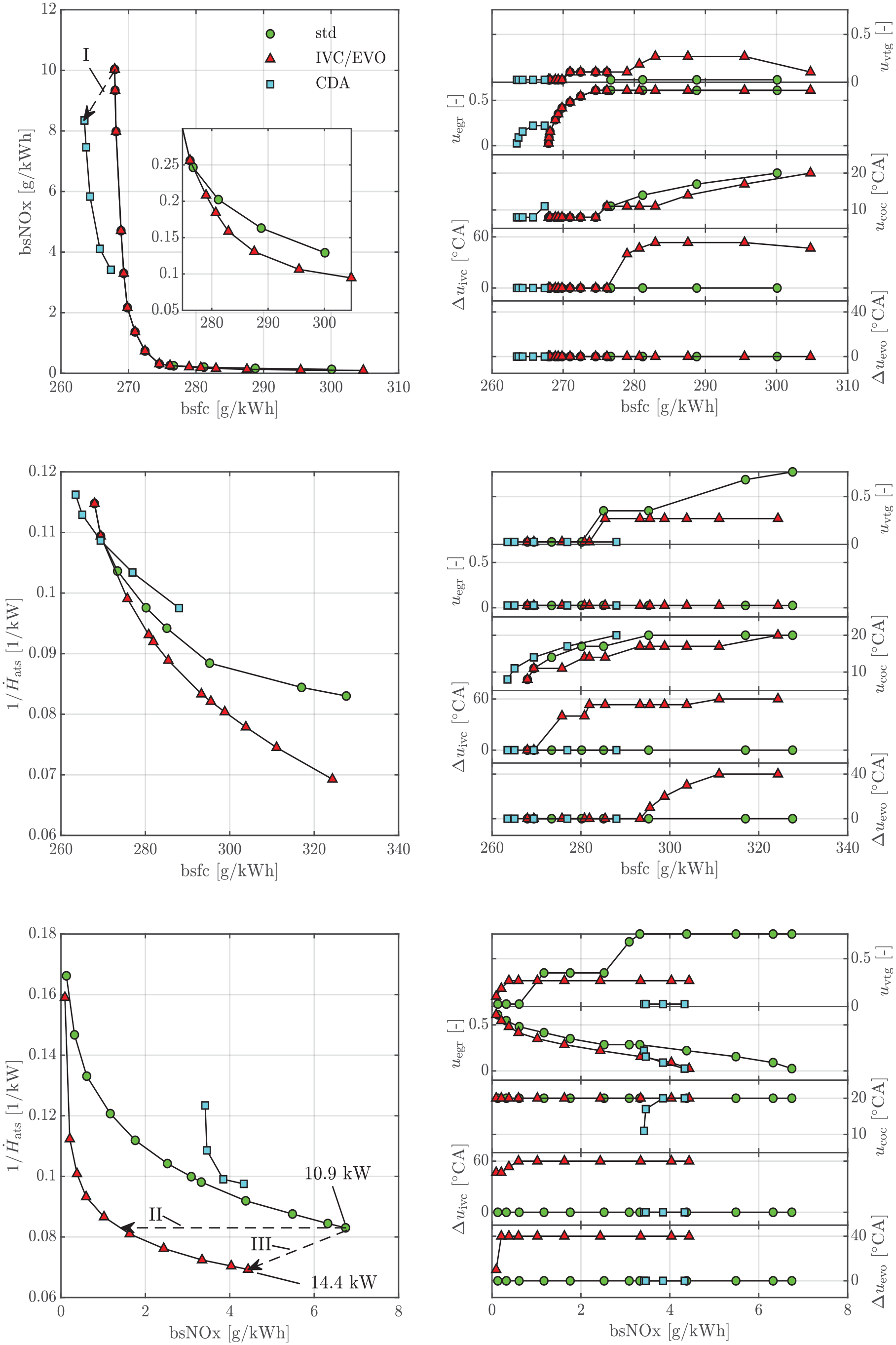
Pareto-optimal trade-off curves for warm-up operation,
Figure 21, which can be found at the end of the paper, shows the results for stay-warm operation, that is, when
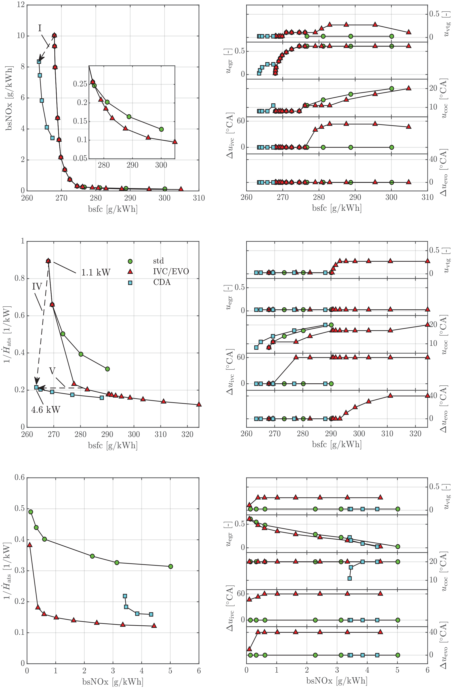
Pareto-optimal trade-off curves for stay-warm operation,
Both operating modes, that is, warm-up and stay-warm operation, demonstrate the advantage of a VVT for a single load point, either by using variable valve timing or cylinder deactivation. The obtained Pareto-optimal solutions can be used for a variable engine calibration to obtain fuel-optimal solutions that are compliant with respect to pollutant emission limits as presented in recent studies.14–16 The quantification of the exact benefit of a VVT for a pre-defined transient cycle will require the identification of the presented models for various engine speeds and the inclusion of a dynamic model for the ATS.
Conclusion
We have presented a cycle-discrete cylinder model for engines with negative valve overlap. The model, which is based on first principles, is identified with measurements of standard valve timing and can simulate the following VVT strategies: early IVC, early EVO, and cylinder deactivation. Embedded into an existing mean-value model of the air path, we are able to quantify the effects of various VVT strategies on fuel consumption, engine-out NOx emissions, and enthalpy to the ATS at engine steady-state. The complete engine model without VVT has been validated on a CI engine. The model extensions, which allow for the simulation of a VVT, have been validated on a SI engine retrofitted with a VVT. The engine model presented enables a first evaluation of the advantages of an existing engine layout without the need to install a VVT. This is highlighted in the case study, which demonstrates how various VVT strategies can improve engine performance for both warm-up operation and stay-warm operation at part load. For both modes, the case study shows that variable valve timing significantly improves on the trade-off between engine-out NOx emissions and exhaust enthalpy flow when compared to the standard engine strategy. For warm-up operation, cylinder deactivation is unfavorable since the overall mass flow and hence the enthalpy flow to the aftertreatment system are reduced. For stay-warm operation, cylinder deactivation is more favorable than variable valve timing as efficiency is greatly increased for equal levels of exhaust enthalpy flow. In addition, cylinder deactivation achieves lower fuel consumption, lower NOx emissions, and an increased enthalpy flow when compared to the fuel-optimal standard engine strategy.
Footnotes
A Appendix
Declaration of conflicting interests
The author(s) declared no potential conflicts of interest with respect to the research, authorship, and/or publication of this article.
Funding
The author(s) disclosed receipt of the following financial support for the research, authorship, and/or publication of this article: The authors gratefully acknowledge the funding by the Swiss National Science Foundation (SNSF) and the contribution of the Research Unit (FOR) 2401 “Optimization Based Multiscale Control for Low-Temperature Combustion Engines” supported by the German Research Foundation (DFG).