
Abstract
The current study aims to experimentally investigate the effect of atomizer and cross-flow velocities on liquid and gelled Jet A-1 fuels. For gelled Jet A-1, Jet A-1 liquid, Thixatrol® ST and rectified xylene are the base fuel, gellant and solvent, respectively. Gelled Jet A-1 is prepared by adding 85% by weight of base fuel along with 7.5% by weight of gellant and solvent, each at optimum processing conditions. Atomization using a simple-plain-orifice atomizer is investigated to understand its effect on Jet A-1 gel fuel break-up without air cross-flow. Based on the investigation from qualitative flow visualization and quantitative analysis of Jet A-1 gel fuel break-up, a modified simple-plain-orifice atomizer called an internally impinging air-blast atomizer is made. Primary atomization using this new atomizer is studied to understand the break-up of liquid and gelled Jet A-1 gel fuels without any air cross-flow. Secondary atomization of liquid and gel fuel is investigated by transversely injecting fuel into different low-speed subsonic air cross-flow environments. Laser sheet Imaging (LSI) technique is used to capture spray images of both fuels. Break-up mechanisms of both liquid and gel fuels were observed, and the results were compared. Information on the cross-flow air mass flow rate effect on the liquid and gel spray is extracted by developing an algorithm in MATLAB using an image processing tool. Relative droplet size distribution of liquid and gel spray revealed their dependence on cross-flow air mass flow rate. Total droplet count of both liquid and gel fuel decreases significantly as the cross-flow Reynolds’ number increases. At higher cross-flow Reynolds’ number, gel droplets in the flow are observed to be more as compared to liquid fuel.
Introduction
In the aerospace industry, liquid jets injected into a cross-flowing airstream have numerous applications. Thrust vectoring, after-burner fuel injection, and fuel injection in gas turbine, ramjet, and scramjet engines are a few examples. Even though so many researchers conducted several studies on the transverse injection of liquid Jet A-1 fuel to understand the flow and break-up characteristics of this fuel, a thorough understanding is still required to optimize the atomizer’s operating parameters as well as the type of atomizer used for the atomization process for better performance in an aircraft engine.
Rayleigh demonstrated that capillary forces were the primary factor and that the liquid jet would break into sections about 4.5 times the length of the jet. 1 Factors such as liquid viscosity and surrounding medium were discovered to have an effect at higher jet velocities. Rayleigh’s work was later expanded by several researchers, including Weber. Aerodynamic forces are present even in the case of a stagnant receiving fluid. When a jet is deformed from a constant cylindrical cross-section, the external pressure varies across the surface, being greater where the jet is smaller in diameter. This hastens the break-up process. However, liquid viscosity tends to slow it down. A first approximation to the regime where aerodynamic forces become important can be obtained by comparing aerodynamic forces to surface tension forces. An approximation can be established by comparing the aerodynamic forces to those of surface tension to determine the regime where aerodynamic forces become significant. The critical Weber number, which distinguishes between the regime controlled by surface tension and the one impacted by the combined forces of surface tension, aerodynamic forces, and liquid viscosity, is an approximation of the ratio of these forces. The first regime will be known as the “Rayleigh regime,” while the second will be known as the “Weber regime.” In the Weber regime, the relative velocity of the jet with respect to the gas was nearly parallel to the jet axis. The resulting aerodynamic forces, coupled with and exaggerated surface tension instabilities, resulted in “waves” in which the jet diameter varies with position along its axis in a sinusoidal pattern. When the relative gas velocity causes waves to grow on the jet surface, a slightly different mechanism occurs. These waves may be capillary or acceleration waves, and will be referred to as the “capillary wave” region and the “acceleration wave” region for convenience.
The capillary wave region differs from the Rayleigh region, such that capillary waves are generated by wind, whereas the Rayleigh region only involves surface tension instabilities. In both cases, the waves are thought to be caused by some sort of disturbance, such as internal turbulence, foreign gas bubbles, pressure fluctuations, and so on. When the aerodynamic forces are sufficiently large, the capillary wave region and the Weber region are established. The injection of a jet at very high velocities or into a high-velocity gas stream are two examples. When the wavelength of the oscillating jet exceeds a critical magnitude, acceleration waves take over. When the wavelength is less than this critical value, capillary waves take over. The generated ligaments are unstable due to their high surface energy-to-mass ratio, and any slight perturbation will cause them to collapse into drops. The resulting drops will be assumed to have a diameter proportional to the ligament diameter, which in turn is proportional to the wavelength. From this, it is evident that the atomization of fuel also depends on the type of wave formation. 1
The effect of airstream momentum on mean drop diameters of water jets injected cross-stream from simple orifices into axial-flow airstreams was experimentally investigated by Ingebo. 2 He concluded that the wavelength is relatively long for liquid jet atomization with low-momentum airstreams and low Weber numbers, and the ratio of orifice diameter to critical wavelength is low due to the predominance of capillary wave type of break-up. While the wavelength is relatively short in high-momentum airstreams, the ratio of orifice diameter to critical wavelength is high due to the predominance of an acceleration wave type of break-up.
The aerodynamic influence of combustor inlet air pressure on water jet atomization is studied by Ingebo et al. 3 He observed that both aerodynamic and capillary wave break-up occurs during water jet atomization. He concluded that at low airstream mass velocity, capillary wave break-up takes place, but at high airstream mass velocity, aerodynamics wave break-up of liquid jet takes place during its atomization process. Olyaei et al. 4 studied the behavior of liquid jet and liquid sheet injected into a low-speed cross-flow, experimentally. Three different break-up regimes were observed by the authors during its atomization process called Rayleigh break-up, column-bag break-up and bag break-up regimes. Madabhushi et al. 5 investigated the atomization of a liquid jet in cross-flow at a low Weber number and identified three break-up regimes such as column break-up, mixed break-up and surface break-up regimes. Zhao et al. 6 studied the crosswise distribution characteristic of kerosene spray in air cross-flow at high temperature and high pressure. The authors concluded that the spray’s spreading area, width, and height increase with the increase in the fuel/air momentum ratio. The primary break-up of a rounded water jet was experimentally studied by Pulat and Parthasarathy 7 in a low Weber number gaseous cross-flow, and they identified different wake regions at the immediate rear portion of the jet in the momentum ratio ranging from 10 to 40. Liquid jet atomization in subsonic cross-flow was experimentally investigated by Eslamian et al. 8 in elevated pressure region and temperature region. Although the spray penetration height at room temperature and pressure are primarily correlated with the fuel-air momentum flux ratio, the authors concluded that at different pressures and temperatures, additional parameters influence penetration and trajectories as well. Tambe et al. 9 observed two different break-up mechanisms during his experimental study of liquid jets injected into subsonic cross-flow. He concluded that column break-up occurs at low momentum flux ratio and low Weber number. An increase in either momentum flux ratio or Weber number leads to a change in break-up mode to surface break-up. Also, he observed that there is a mixed break-up mode, which is defined as a finite region between these two modes in which both mechanisms are active.
Patil and Sahu 10 inspected water spray disintegration using a laser-sheet-illumination technique using a six-jet-air-blast atomizer. They measured mean droplet size and velocity using a Phase Doppler Particle Analyzer (PDPA) for a twin-jet-air-blast atomizer. They found that at constant liquid jet’s Reynolds’ number, aerodynamic Weber number, and momentum flux ratio, the radial expansion of the water spray was greater for the twin-jet air-blast atomizer than the six-jet-air-blast atomizer. Stenzler et al. 11 experimentally investigated the transverse liquid injection into both heated and cold air cross-flows. The authors concluded that increasing the momentum flux ratio increased the penetration of the injected jet in the cross-flow. Increasing the Weber number reduced overall spray penetration and reduced the mean drop sizes of the sprays. Amighi 12 studied the break-up and atomization of water jets in continuous subsonic cross-flow using a laser light sheet illumination technique. He identified three modes of break-up regime called column break-up, surface/shear break-up and multimode break-up and reported that during column break-up, aerodynamic forces cause the break-up of the water jet. The aerodynamic disturbances are smaller, and the droplet sizes are more uniform along the jet in the surface/shear break-up regime. He also observed that both break-up mechanisms are active in the multimode regime. Because both mechanisms are always present, the distinction between the regimes is not clear and is generally defined arbitrarily. Kihm et al. 13 performed a flow visualization study to qualitatively examine the different atomization performances of different gas nozzles. The authors concluded that the SN-Type nozzle (converging nozzle which produces under-expanded sonic gas jets) produces a wider spray than the CD-Type nozzle (converging-diverging nozzle which produces over-expanded supersonic gas jets), most likely because the SN-Type nozzle has a wider gas jet (in the absence of liquid) than the CD-Type.
Freitag et al. 14 studied the kerosene jet atomization characteristics in cross-flowing air and discovered that nozzle diameter, as well as momentum flux ratio, had a strong influence on jet penetration. Li et al. 15 experimentally investigated the injection of liquid kerosene into a high-pressure subsonic cross-flow. The authors found that the Weber number had no significant effect on kerosene jet penetration at room or high temperatures. They concluded that the penetration of liquid kerosene injection into cross-flow was greater at higher air temperatures than at room temperature. The cross-flow to injected jet temperature ratio affects jet penetration significantly. Kerosene jet atomization characteristics in cross-flow were studied by Li et al. 16 They reported that the SMD of atomized droplets decreased as the injection pressure drop, momentum flux ratio and cross-flow Mach number increased. Song et al. 17 experimentally studied the influence of the exit orifice geometrical shape of six different injectors on the liquid jet spray characteristics. The authors reported that a circular exit injector performed better than one with an elliptical-exit injector. Fan et al. 18 investigated the atomization characteristics of RP-3 aviation fuel using a pressure-swirl-atomizer and obtained their findings using the MATLAB image processing technique. They performed experiments at various pressure drops and fuel temperatures and discovered that increasing the pressure drop changed the shape of the liquid film from “onion” to “tulip” and a fully developed spray cone. They also discovered that the fuel temperature influenced the shape and length of the liquid film under different pressure drops. The authors concluded that as pressure drops and fuel temperature increases, so does the width of the fuel stream. Fan et al.19,20 conducted numerous experiments to optimize the dual orifice atomizers based on the mass flow and atomization characteristics and discovered a new-dual orifice atomizer. The authors discovered that as dynamic pressure in the pipeline increases, three distinct patterns of main-stage liquid film and pilot-stage liquid film appear (separation-fusion-secondary separation). They concluded that altering the atomizer structural parameters improved the atomization of the fuel.
Over the decades, many researchers conducted several studies on the atomization characteristics of liquid fuels, mixing methods and atomization and its effects on combustion performance, and penetration of liquid fuels under transverse jet conditions. The influence of various factors such as injection mode,7,10,14,15,17 liquid fuel physical properties, 7 atomizers exit orifice diameter,17–20 droplet-diameter,21,22 droplet-size-distribution,22,23 and droplet-velocity7,21 were investigated. From earlier investigations by various researchers, they found that the major drawback of liquid fuel is that it is extremely corrosive and noxious to both humans and the atmosphere in the event of accidental leaks and spills. 24
As a result, the researchers implemented the idea of gelling the Jet A-1 fuel for superior safety reasons. 25 In general, gel fuels exhibit shear-thinning and thixotropic behavior. Briefly, due to the viscoelastic nature of gelled fuels, they are far superior to liquid fuels in terms of safety. It has lower vapor pressure, no sloshing, minimal spillage, and absorption by the soil. Analogous to liquid fuel, gels can be flexibly packed, stored over a long period, and easily transported. It is essential to understand the flow and break-up characteristics of both the Jet A-1 liquid and Jet A-1 gel fuels.
Natan et al. 24 examined several features of Jet A-1 gel fuel and concluded that rheology is the most crucial factor in studying the flow characteristics, atomization characteristics, and combustion behavior of gel fuel. Rheological properties of various gellant combinations were studied by Rahimi et al. 26 to create gelled fuels, oxidizers, and inert simulants. This feature enabled the rheological matching of gel fuels to gel oxidizers or gelled water-based simulants to actual gel propellants, reducing hazards and costs during propellant development testing. Santos et al. 27 and Arnold et al. 28 experimentally investigated the characterization of JP8 and RP1 gel using fumed silica as a gelling agent. The gel has a high viscosity and good stability when prepared in a short mixing time with high mixing acceleration. The degree of thixotropy increased as the gelling agent concentration was increased. Mishra et al. 29 studied the flame structure of gel droplets during combustion. The authors studied the effect of gellant concentration on the burning rate of the gel fuel and reported that, increasing the gelling agent concentration, decreases the burning rate constant initially and then stabilizes, resulting in a reduction in the calorific value of the gel fuel. Kim et al. 30 examined the rheology of gel fuel (Jet A-1) by introducing various gellants and found that the viscosity of the gel increases as gellant concentration increases.
Mishra et al.31,32 conducted a study on Jet A-1 gel fuel and reported that increasing the processing temperature and Jet A-1 gellant concentration enhanced the structural stability of the gel. They also reported that increasing the processing temperature and Jet A-1 gellant concentration reduces the phase separation of gel but reduced atomization quality. The cumulative mass flow rate of Jet A-1 gel fuel decreases viscosity but increases the Sauter-mean-diameter. Kim et al. 33 analyzed the effect of slurry composition and rheological properties on the spray formation and break-up process of kerosene, kerosene gel and slurry at room temperature. The aluminized gel is affected by particle content and its diameter. The liquid film thickness was found to increase as the viscosity of the aluminized gel with particles increased. Ardhianto et al. 25 investigated different kerosene-based gels to understand their rheological properties and concluded that the degree of shear-thinning rises as the solvent concentration increases. Yang et al. 34 investigated the kerosene-based metallized gel to understand its rheology. The authors observed that raising the gellant and particle concentration raises the viscosity of the gel. In contrast, increasing the gellant concentration decreases the surface tension, and by increasing the particle concentration, surface tension increases. Carer et al. 35 studied the effect of parameter variation on the viscosity of ethanol gel propellants using methyl cellulose as a gellant. The viscosity of the gel was found to decrease with increasing temperature until 320 K, after which it rose. All the investigated gels exhibit an initial shear thickening behavior at low shear rates, which has the advantage of reducing fuel sloshing. They concluded that up to a shear stress of 25.97 Pa and a shear rate of 0.41 s−1, the gel behaves elastically, after which it behaves in a shear-thinning manner, and its viscosity decreases. The shear-thinning behavior of gel is observed at high shear rates at decreased viscosity. Mansour and Chigier 36 investigated the spray characteristics of visco-inelastic (Water) and viscoelastic liquids (Polymer solutions – Xanthun gum and Polyacrylamide solutions) using a co-axial-twin-fluid atomizer. They concluded that viscoelastic liquids were much more difficult to atomize than visco-inelastic liquids. The authors discovered that Newtonian liquid break-up patterns resembled those of water sprays, whereas non-Newtonian liquid break-up patterns were noticeably different. They concluded that in non-Newtonian liquid-breaking mechanisms, the ligaments stretch a lot before breaking up, resulting in long threads of liquid attached to droplets. Chojnacki et al. 37 experimentally studied the significance of dimensionless numbers such as Reynold’s number, Weber number, and Ohnsorge number on the spray characteristics of gel fuel. The authors confirmed that at higher Weber numbers, circular waves (Kelvin-Helmholtz instabilities) emanated from the point of impingement and propagated through the sheet with short wavelengths. These instabilities tear the gel sheet into ligaments but don’t produce droplets. Guglielmi 38 investigated the spray characteristics of both liquid and gelled boron-slurry fuel at atmospheric pressure using two air-blast atomizers in reaction-free flow conditions. He reported that high-viscosity gel fuels produced significantly larger particles than low-viscosity liquid fuels, when these fuels passed through air-blast atomizers under similar conditions. Furthermore, they discovered that nozzles designed for the effective atomization of low viscous liquid fuel may not be appropriate for the atomization of high viscous gel fuels. Urbon 39 researched the combustion behavior and spray characteristics of metallized- slurry fuel (JP-10/B4 C) and found that a simple air-blast atomizer does not produce sufficient number of small particles. He reported that for effective combustion of a boron-slurry gel, at reasonable atomizing air mass flow rates, particle size was so important. During testing under-reacting flow conditions, he concluded that the air-blast atomizer failed to sustain steady combustion of the slurry fuel for ramjet applications. Gafni et al. 40 experimentally investigated gel hydrocarbon fuel with and without metal additives to check the ramjet’s operation and performance. They found that the atomization characteristics of the metal gel fuel were poorer than those of liquid-kerosene and non-metallized gel fuel. The authors claimed that gels perform worse than liquid fuels, but that this can be rectified by using the right gellants, procuring better atomizers, and optimizing the combustor shape. They also concluded that the maximum temperature and combustion efficiency of the ramjet combustor was achieved by using nickel-coated aluminum gel as fuel. Padwal et al. 41 reviewed several features of gel fuels, straddling from the rheology to the combustion behavior of gel fuels and their droplets. They concluded that gel propulsion is still in its early stages and that more research is required to replace it with solid, liquid, and hybrid propulsion fuels.
Many current aerospace propulsion systems rely on liquid fuel combustion. Before these liquids can be combusted, they must first be sprayed in a two-step process called as atomization. When a liquid jet breaks up into huge drops, this is referred to as primary atomization. Secondary atomization occurs after a drop has already formed but has been broken up further due to instability. This procedure sets final drop sizes, which affect the liquid’s evaporation and mixing rates, influencing the efficiency of the combustor. 42 Few investigations have been undertaken on the secondary atomization of viscoelastic non-Newtonian liquids such as gels. These compounds have exceptional promise as aircraft fuels since they are safer to handle than Newtonian liquid fuels such as Jet-A, Jet-A-1, JP8, and RP1. These non-Newtonian fuels’ physical and chemical characteristics alter as the liquid fuel is converted into gel fuel. The viscosity of the gel fuel increases compared to traditional liquid fuels once it is produced from the liquid fuel. The density of gels increases significantly during storage, especially if metal particles are added. 43 Similarly, studies have been undertaken on the majority of features of gel propulsion, such as gel fuel production, viscoelastic nature, the atomization process of gel, gel combustion, and applications. Kerosene-based gel fuels have been utilized in rocket launchers, ramjets, aircraft afterburners and furnace combustion. Furthermore, research is needed to comprehend its composition, flow, and (secondary) atomization properties in order to increase these engines’ and furnace combustion efficiency.
The novelty of this current research work is to study the atomizer effects without and with cross-flow on Jet A-1 liquid and Jet A-1 gel fuels. From the literature, it was observed that the comparative flow physics and characteristics of Jet A-1 liquid and Jet A-1 gel fuel using an internally impinging air-blast (IIAB) atomizer in low-speed subsonic air cross-flow (LSSACF) had not been addressed. Similar to cross-flows affecting liquid fuel break-up,
43
the break-up characteristics of Jet A-1 liquid and Jet A-1 gel fuels necessitate further examination for the safe introduction of gel fuel and an atomizer to inject and atomize this viscoelastic gel in the combustor for aerospace propulsion applications. The flow characteristics of this conventional Jet A-1 liquid and Jet A-1 gel fuels will be improved in particular by selecting the best atomizer and atomization process. This will find a way to dissipate the Jet A-1 liquid and Jet A-1 gel fuels into sheets and ligaments and then further disintegrate them into spherically shaped droplets to further increase the evaporation rate in order to improve the efficiency of combustion. Eventually, it will lead to improved performance and lower costs for aerospace vehicles in the future. As a result, the current research focuses on the effect of an atomizer on gelled Jet A-1 fuel without and with cross-flow. For this purpose, Jet A-1 liquid and Jet A-1 gel fuel spray characteristics are studied without any cross-flow using a simple, plain-orifice atomizer. Based on the atomization results of Jet A-1 liquid and Jet A-1 gel fuel spray characteristics without cross-flow and using a simple-plain-orifice (SPO) atomizer, this atomizer is modified, and a new atomizer called an IIAB atomizer is developed. Atomization of Jet A-1 gel fuel was checked in the test section without any cross-flow using the newly developed IIAB atomizer. This newly developed IIAB atomizer is used to investigate the liquid Jet A-1 and Jet A-1 gel fuel flow physics using a flow visualization technique. Further, the effect of cross-flow air mass flow rate on the flow characteristics of Jet A-1 liquid and Jet A-1 gel fuel is studied experimentally using the IIAB atomizer. The comparative spray characteristics of the Jet A-1 liquid and Jet A-1 gel fuels were investigated for different cross-flow air velocities (Vcf) and cross-flow Reynolds’ numbers (Ref) by varying the cross-flow air mass flow rates (
Experimental methods
Gel fuel preparation set-up
A laboratory stirrer with a three-bladed impeller (REMI RQ-122 model), an electric heater, a gel fuel-preparing vessel, a vessel with a water bath, and a digital probe-type thermometer comprise the gel fuel preparation setup as shown in Figure 1. To mix the fuel and solvent Jet A-1 gellant, the laboratory stirrer is used. It is powered by a 1/20 hp electric motor with 0.6 A capacity, which has a maximum rotational speed of 4000 rpm and is controlled by a variable speed regulator. To keep the water bath temperature stable, an electric heater was used. A digital probe thermometer with an operating temperature range of −50°C to 300°C is used to measure the fuel processing temperature.
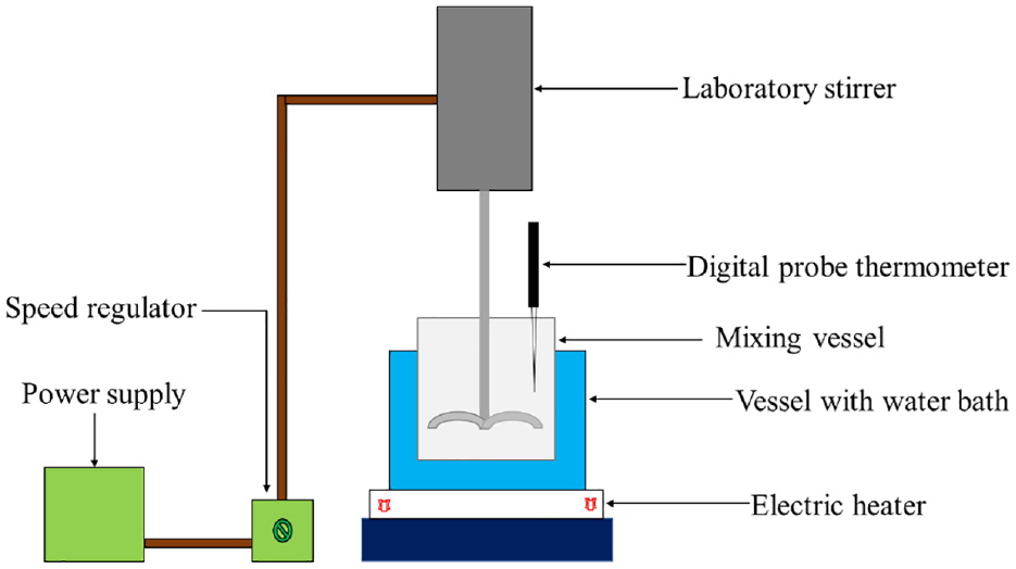
Gel fuel preparation set up.
Jet A-1 gel fuel preparation and flowability study
The designed in-house gel fuel preparation test setup was used to prepare the Jet A-1 gel. Initially, an organo-gel solution was made by combining 7.5% by weight of Rectified xylene (solvent) with 7.5% by weight of Thixatrol® ST (gelling agent) and stirring continuously at a low speed of 600 rpm for 10 min. The organo-gel solution is then mixed with 85% by weight of Jet A-1 liquid fuel. The entire solution is mixed at 2200 rpm and warmed until the target temperature (Tproc) 63° is reached, which is considered optimum for Jet A-1 gels. 31
These gel samples were prepared by mixing the organo-gel solution with Jet A-1 liquid fuel in a vessel equipped with a three-bladed impeller. The mixing vessel is inserted into a water bath. A constant temperature is maintained in the water bath by varying the voltage in the electric heater, which is controlled and monitored by a digital probe-type thermometer. To form a homogeneous gel slurry, the mixing process was extended for another 15–20 min. The gel slurry is then left undisturbed for 24 h and kept at room temperature until the formation of Jet A-1 gel fuel. For the experiments, three samples of the same gellant concentration were prepared for repeatability tests. The gel samples are then tightly packed into the storage vessel, and are now ready for testing.
For gel fuels, knowledge of non-Newtonian fluid rheology allows for control over flow through the delivery system and disintegration of the gel. Gel samples were subjected to rheological
44
and spray testing to better understand their flowability, enabling the design of a suitable atomizer. An Anton Paar MCR-302 rheometer was used to determine the shear rate behavior of gel fuel. Our previous work
44
provides detailed information about the rheological measurement instrument and procedure. The shear flow test was conducted on the prepared gel sample by ramping the shear rate (
Jet A-1 liquid and Jet A-1 gel spray in LSSACF – Test setup
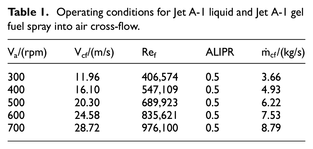
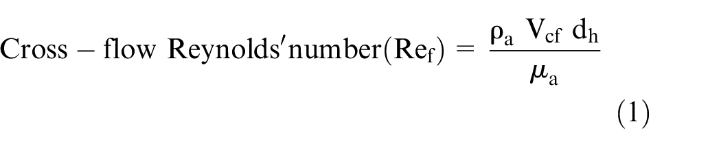
The experimental rig shown in Figure 2 was developed to study the flow physics of Jet A-1 gel spray in LSSACF 4 and without any air cross-flow and Jet A-1 liquid spray in LSSACF. This setup consists of an open-circuit air supply system, a fuel supply system and an optical arrangement for capturing spray images during testing. An open-circuit air supply system consists of a variable-speed axial wind blower for cross-flow air supply to the test section. Cross-flow air was guided into a 50 × 50 × 50 cm (length, height, width) acrylic duct connected to the wind tunnel at one end and open to the atmosphere at the other end. The cross-flow air was supplied by an axial wind blower with a maximum flow rate capacity of 7.18 m3/s. The axial wind blower was powered by a 25 HP electric motor spinning at a maximum speed of 800 rpm. Axial wind blower speed (Va) was measured as well as controlled by varying the electric motor’s supply voltage via a multi-turn potentiometer (MEXICO BOURNS 3590S-2-103L) in the alternating current (AC) drive control panel, which changed the power supply to the electric motor. The cross-flow air velocities were estimated using a 64-channel Miniature Pressure Scanner (Scanivalve MPS4000). Total and static pressures were measured for various Va. The cross-flow air velocity (Vcf) was determined using a pressure rake with 11 ports located at five different positions along the breadth and height of the test chamber. Six runs were done for each position, and the mean Vcf was determined by utilizing pressure data from each position, as shown in Table 1. The experiment’s uncertainty in measuring Vcf is found to be 1.56% for all cross-flow experiments. Variation of cross-flow air velocity (Vcf) with axial wind blower speed (Va) and cross-flow air mass flow rate (mcf) with cross-flow Reynolds’ number (Rf) are plotted and it is shown in Figure 3.
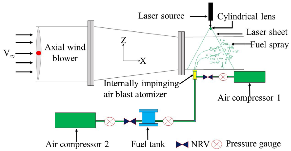
Schematic of an experimental setup for investigation of Jet A-1 liquid and Jet A-1 gel spray.
Operating conditions for Jet A-1 liquid and Jet A-1 gel fuel spray into air cross-flow.
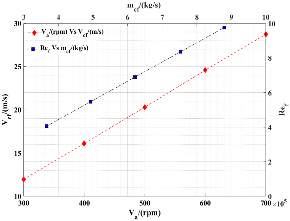
Variation of Vcf with Va, and
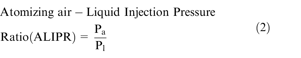
The fuel supply system consists of a fuel storage tank of 500 cm3 volume to store the Jet A-1 liquid and Jet A-1 gel fuel. This fuel tank is connected through the feeding pipeline to an atomizer which is installed on the bottom wall of the test chamber, 8.5 cm downstream from the cross-flow air entrance. The orifice of the atomizer is installed flush with the bottom wall of the test chamber to inject the gel and liquid jet into the test section for the different studies. A single compressor is used to provide pressurized air to a simple, plain-orifice atomizer. In contrast, two air compressors were used to provide pressurized air to the IIAB atomizer. The details of a simple, plain-orifice atomizer and an IIAB atomizer are described in the design details of atomizers section. The test fuel was transversely injected into the test chamber at a constant atomizing air-to-liquid injection pressure ratio while the fuel tank was pressurized with compressed air. For all studies without and with air cross-flow, an Atomizing air-Liquid Injection Pressure Ratio (ALIPR)44–46 of 0.5 was achieved using two portable air compressors. A simple, plain-orifice atomizer is introduced first to test the test fuel, followed by an IIAB atomizer. The air passing through the micro-air orifices to generate the initial break-up of the test fuels within the IIAB atomizer is referred to as atomizing air.
Design details of atomizers
A simple, plain-orifice atomizer is used initially to understand the effect of an atomizer on gelled Jet A-1 fuel without cross-flow. For this purpose, a simple, plain-orifice atomizer is designed and fabricated. Hence, this SPO atomizer consists of a constant-area circular duct followed by a convergent nozzle portion with an exit orifice diameter of 1 mm and a total length of 25 mm. The design details of this SPO atomizer are shown in Figures 4(a) and (b). Later, a newly modified atomizer called an IIAB atomizer was used to study the spray characteristic of gel fuel with and without cross-flow. Furthermore, the effect of an IIAB atomizer on liquid Jet A-1 fuel with air cross-flow was studied. Figure 4 depicts the IIAB atomizer’s design details. An IIAB atomizer is composed of six micro-air orifices (diameter of atomizing air holes, dj = 0.5 mm) located 5 mm upstream from the atomizer exit orifice (d0 = 1 mm), at the end of the nozzle’s converging part (converging half-angle, =7°) and surrounded by a mixing chamber. Pressurized air was delivered to the fuel supply line as well as the micro-air orifices through the mixing chamber to generate the impinging micro-air jets to atomize the fuel within the atomizer. These micro-air jets blast the gasoline in all directions. This allows for a high shearing force, resulting in the early breakdown of extremely shear rate-dependent gelled fuel and low-viscosity liquid fuel within the atomizer. As a result, Jet A-1 liquid and Jet A-1 gel spray were produced in the test section for further investigation.
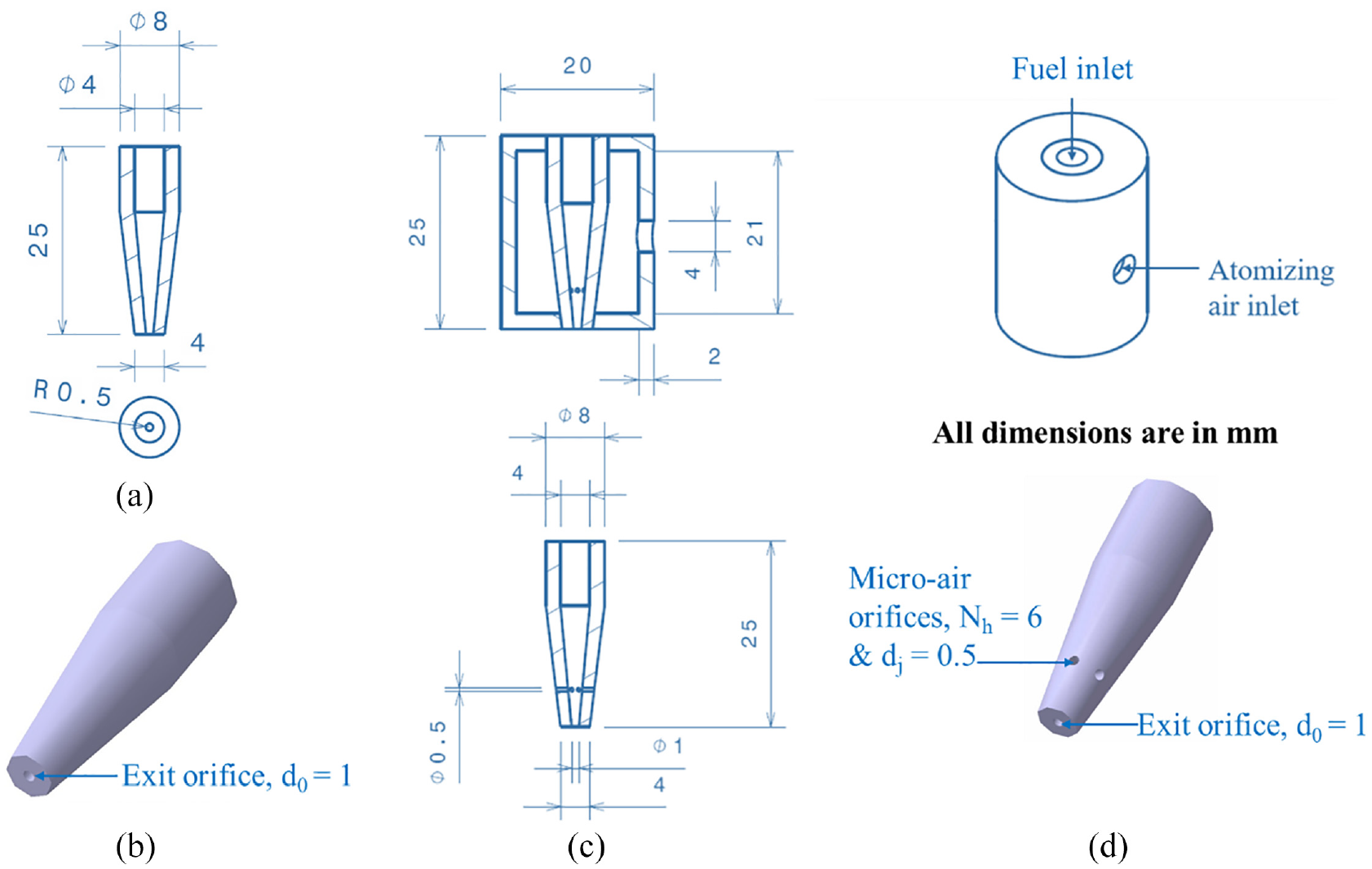
Design details of the SPO & IIAB atomizer: (a) 2D cut section view – SPO atomizer, (b) 3D view – SPO atomizer, (c) 2D cut section view – IIAB atomizer, and (d) 3D view – IIAB atomizer.
Experimental flow conditions
All experiments were carried out under atmospheric circumstances, with the working liquids being Jet A-1 liquid fuel and Jet A-1 gel fuel. The significance of the atomizer in the atomization process is confirmed first by testing the gel fuel using an SPO atomizer without any air cross-flow. Later the IIAB atomizer is used to test both the liquid and gel fuels without any air cross-flow. After a thorough analysis of both atomizers’ behavior, an IIAB atomizer is selected for further investigation on liquid and gel fuel with air cross-flow. At varying air velocities in the test chamber, Jet A-1 liquid and gel fuels were introduced at constant injection pressure. The injection pressure for the atomizing air of 30 psi (gage Pressure) and the fuel injection pressure of 60 psi (gage Pressure) in the atomizer were maintained and held constant throughout all the experiments. Hence, it yields an ALIPR of 0.5 using equation (3). The properties of Newtonian and non-Newtonian liquids, as well as air, were evaluated at 25°C and atmospheric pressure, which corresponded to the conditions under which the tests were carried out. The axial wind blower’s speed, Va/(rpm), was modified from 300 to 700 rpm. Cross-flow air velocity, Vcf/(m/s), ranged from 11.96 to 28.72 m/s, and cross-flow Reynolds’ number, Ref (equation (1)), ranged from 4.06×10⁵ to 9.76×10⁵, with a constant ALIPR of 0.5. Cross-flow air mass flow rate (
The operating parameters are categorized by the following dimensionless quantities46–49:

Imaging system
To visualize and understand the physics of Jet A-1 gelled jet break-up without and with air cross-flow and liquid jet break-up with air cross-flow, the Laser Sheet Imaging (LSI) technique was used. A 100 mW continuous Laser beam of wavelength 532 nm was used as a light source. The lighting system was synchronized to a Digital Single-Lens Reflex camera with a macro lens. A 5 mm cylindrical glass lens is used to generate the laser sheet from a 3 mm collimated laser beam. The laser source and optical lens were positioned correctly to achieve homogeneous illumination across the test section. As illustrated in Figure 2, the created laser sheet was passed through the transparent ceiling of the test section, synchronizing with the test section axis along the XZ plane. Initially, a basic, plain-orifice atomizer is employed to inject the gel fuel cross-wise into the test region. This atomizer was mounted 85 mm downstream from the test section entrance on the test section floor. The generated laser sheet was passed through the test section’s ceiling, focused on the region of interest along the axis of the test section where the atomizer was positioned, and then passed through the test section’s floor. A camera was positioned parallel to the see-through sidewall of the test section, focusing on the area of interest along the plane of the laser sheet. The camera was a Canon EOS 80D DSLR from Stanford Computer Optics Inc., with an 18–135 mm Canon lens that took 6000-by-4000-pixel photographs at 7 frames per second. The camera was positioned so that the main axis of its lens was perpendicular to the transparent side wall of the test portion. Both the atomizers were positioned identically in the test section, and the gel spray was imaged with and without LSSACF. Further, using the IIAB, liquid Jet A-1 fuel was injected and imaged under various operating conditions, as shown in Table 1.
Under each operating condition of the tunnel, 21 images each for background, flatfield and spray were acquired at a frame rate of 7 images per second. These images were averaged, and processed for background and flatfield correction in MATLAB. 44 Image processing was performed to extract quantitative data such as liquid relative droplet size distribution and Jet A-1 gel relative droplet size distribution.
Results and discussion
In this experimental work, the physical characteristics and flow properties of liquid and gel fuels are compared. The rheological character of the non-Newtonian gel fuel is studied by using a shear flow test which is elaborately discussed in our previous work. 44 In the present investigation, a comparative study is carried out on the spray break-up of liquid and gelled Jet A-1 fuel using different atomizers and varied cross-flow conditions. The comparative study is carried out based on qualitative spray image analysis and quantitative data extraction from images like spray penetration, droplet size and relative droplet size distribution using developed MATLAB codes. 44
Physical and thermal properties of liquid Jet A-1 and gelled Jet A-1 fuels
The physical and thermal properties of the Jet A-1 liquid and Jet A-1 gel fuel are determined and compared to understand the phase change while altering the base fuel. Table 2 illustrates the comparative physical and thermal properties of gelled and Jet A-1 liquid fuel. The density of the gelled and Jet A-1 liquid fuel has been determined by identifying the known mass and volume of the respective fuels. The mass of the Jet A-1 gel fuel and liquid fuel was measured using a digital weighing machine, and the volume of the fuel was measured with the help of a measuring beaker. Measurements for the Jet A-1 liquid fuel were relatively easy. The Jet A-1 gel fuel should be carefully packed tightly in the measuring beaker without any air gap to reduce the measurement error. The measured values of mass and volume of the Jet A-1 gel fuel and liquid fuel were used to determine the density of the respective fuels. Thermal tests were carried out to determine the heat of combustion of gelled Jet A-1 and liquid Jet A-1 fuel using the Toshniwal Digital bomb calorimeter arrangement.
Physical and thermal properties of Jet A-1 liquid and Jet A-1 gel fuels.
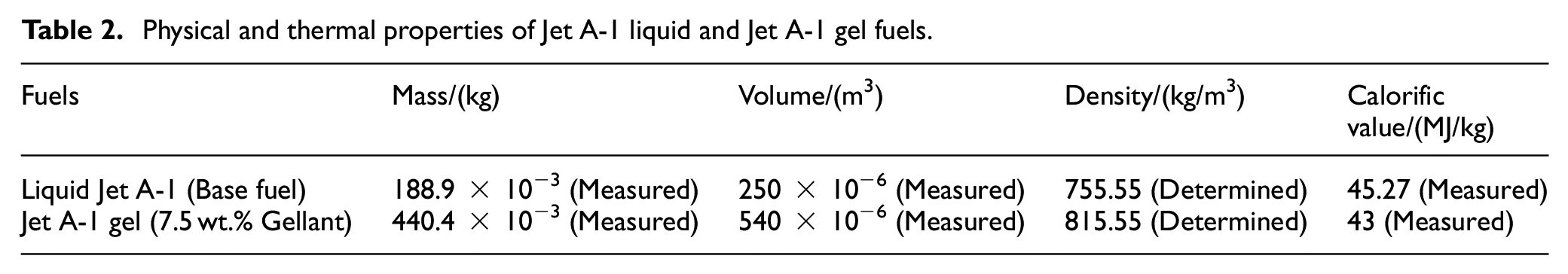
The density of the gel fuel (
All the bomb calorimeter experiments were carried out with the same mass of thread, wire, and an exactly equivalent amount of water. As discussed in the methodology section, the gel fuel sample was taken and tested for complete combustion. The quantified calorific value obtained from the instrument is in the form of cal/gm, which is then converted into an MJ/kg scale. Multiple tests were carried out to check the repeatability of the results. Six repeatability tests were conducted for the prepared gel samples, and the average gross calorific values of the gelled Jet A-1 fuel and liquid Jet A-1 fuel are shown in Table 2. Experimental uncertainty for the calorific value measurement of gelled Jet A-1 fuel and liquid Jet A-1 fuel was found to be within ±0.65% and ±0.12%, respectively. The results obtained from the bomb calorimeter experiment agree well with the existing calorific value results of other aviation gas turbine fuels. The obtained calorific values of gelled Jet A-1 and liquid Jet A-1 fuel are 43 and 45.27 MJ/kg, respectively. It is concluded that the average calorific value of gelled Jet A-1 fuel is 2.2% less than the average calorific value of liquid Jet A-1 fuel. For superior safety reasons, gelled Jet A-1 fuel may be used in the aircraft industry. Gel fuels, in general, tend to reduce accidents during storage and spills because of their visco-elastic properties. Based on the density study, the gelled Jet A-1 fuel is found to be more compact. It is suggested that finding the most suitable metal additives will improve the gel fuel’s calorific value and density impulse, which helps to improve efficiency.
Image processing sequence
Liquid and gelled Jet A-1 fuels were injected into the test sections through the SPO and IIAB atomizers under no cross-flow and varied cross-flow conditions. The spray was imaged using the LSI technique after acquiring the background and the flatfield image using the same technique. For each test case, 21 images were acquired at 7 fps shutter speed of the camera. All raw RGB images are 6000 × 4000 pixels in size, which were cropped to 3311 × 3121 pixels during image processing based on the area of interest. After cropping, the images were averaged, converted to grayscale, and then processed for background and flatfield correction. The corrected images were further processed in Matlab to get spray characteristics of Jet A-1 gel and Jet A-1 liquid fuel, such as relative droplet size distributions, and SMD with and without cross-flow. The entire processing technique is illustrated in Figure 5. Figure 6(a) to (d) shows the generated images at every step of sample image processing for Jet A-1 liquid and gel at a cross-flow airspeed of 20.3 m/s.
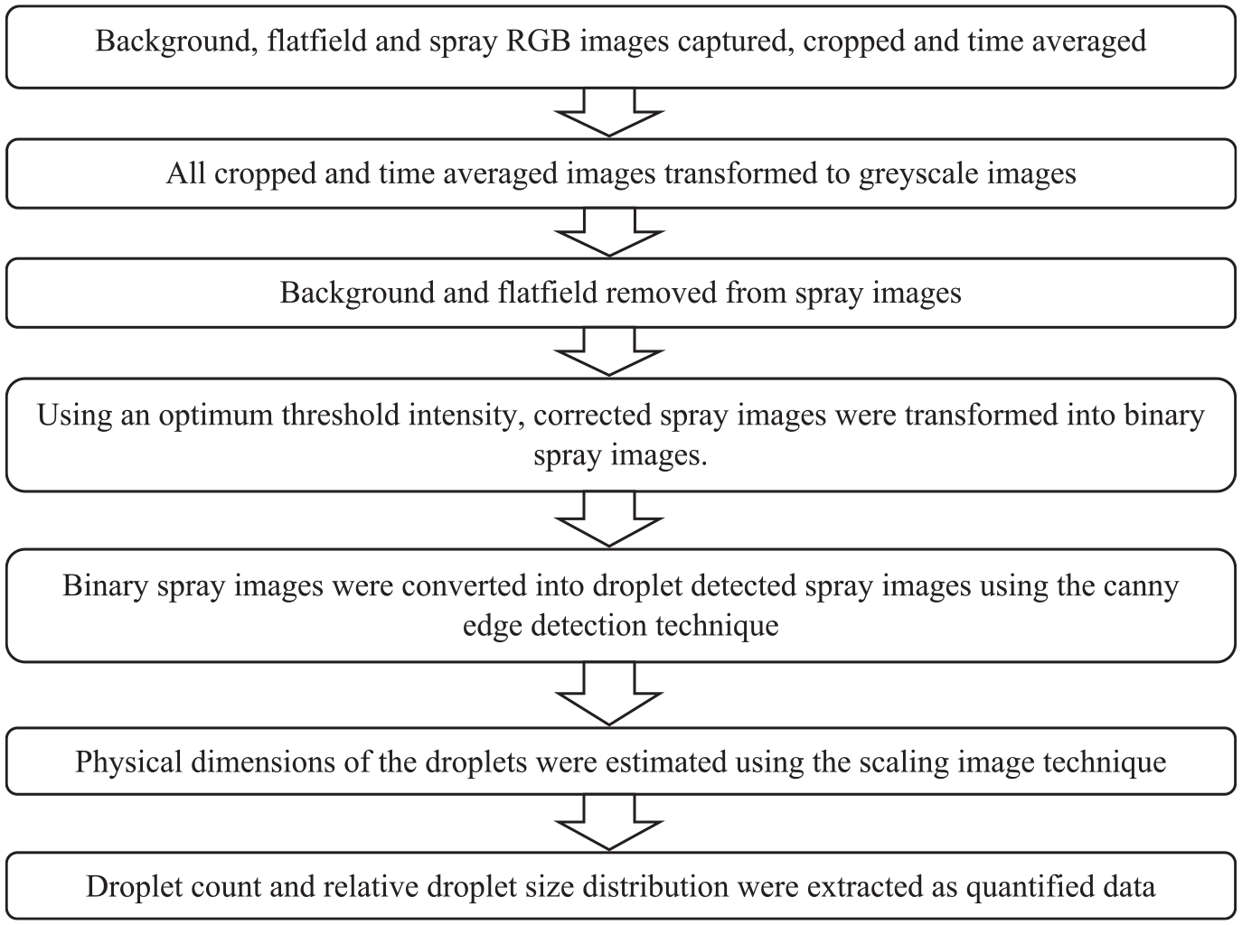
Flow chart for methodology adopted for image processing.
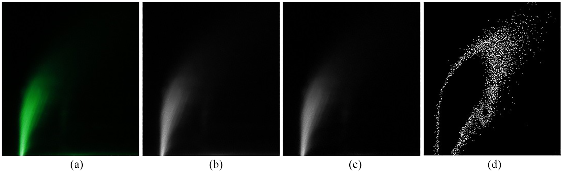
(a)–(d) Sample image processing sequence of Jet A-1 liquid and gel in subsonic cross-flow.
A detailed description of the image processing sequence is discussed elaborately in our previous work. 44 An equivalent image processing approach was applied for all the collected Jet A-1 liquid and Jet A-1 gel spray images at varied operational conditions to determine the Jet A-1 liquid and Jet A-1 gel relative droplet size distribution.
Effect of atomizer on Jet A-1 liquid and gel fuel injection without any air cross-flow
A simple-plain-orifice atomizer is used for the investigation first to understand the penetration and break-up of gel fuel without air cross-flow. The spray was photographed as described in the section on imaging systems. Pictures obtained using the LSI approach were processed in MATLAB to get data on the Jet A-1 gel relative droplet size distributions using an SPO atomizer without any air cross-flow. Figure 7 shows the raw, cropped RGB, grayscale and background corrected flatfield removed gel spray images using an SPO atomizer without air cross-flow. It is observed qualitatively that penetration of continuous gel sheets, and ligaments are visualized in gel fuel injection using an SPO atomizer without any cross-flow. This is because of the design structure of the atomizer as well as the physical characteristics of the gel fuel. It also affects the gel break-up process.
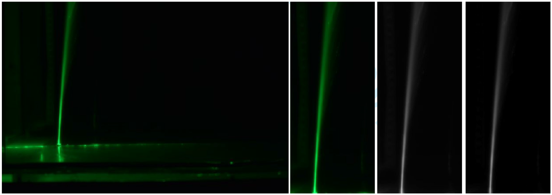
Gel fuel injection of a simple plain orifice atomizer without cross-flow.
Figure 8 illustrates the relative droplet size distribution of gel fuel injected through a simple plain orifice atomizer without any air cross-flow. It is found that the total droplet count of gel fuel injected through the SPO atomizer into the test chamber is only 135 in number, which is very low. Hence, it is quantitatively evident that the primary break-up process of gel fuel does not happen efficiently because of the design structure of an SPO atomizer. Since the SPO atomizer failed to generate desired primary atomization of the gel fuel, it was modified to an internally impinging air blast (IIAB) atomizer. Subsequently, gel fuel was injected into the test chamber through the IIAB atomizer without air cross-flow.
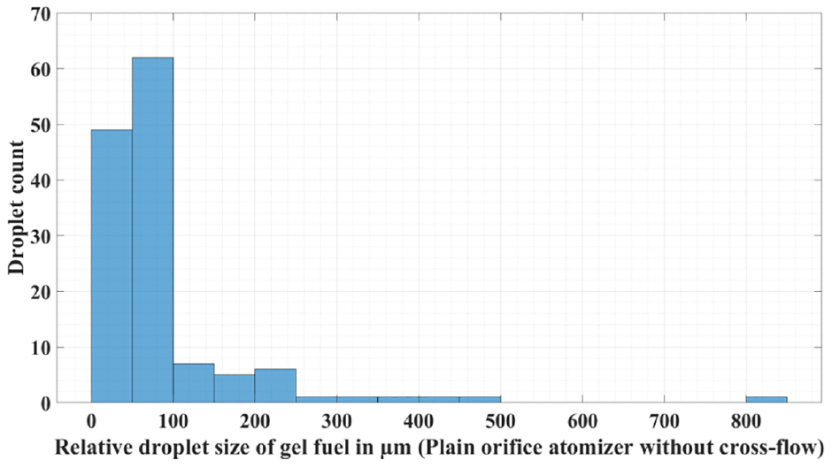
Relative droplet size distribution of gel fuel injection of a simple plain orifice atomizer without cross-flow.
Figure 9 displays the raw RGB, cropped RGB, grayscale, and background removed flatfield corrected gel spray images using the IIAB atomizer without air cross-flow. From this figure, it is observed that the penetration of gel fuel using the IIAB atomizer is less than the penetration of gel fuel injected through the SPO atomizer. Also, continuous gel sheets, ligaments, bigger droplets, and some fine droplets are visualized in and around the periphery of the gel fuel spray injected with the IIAB atomizer. This IIAB atomizer atomizes the highly viscous gel fuel and performs the primary break-up of gel fuel within the atomizer itself. This leads to an enhancement in the atomization quality of the gel and its break-up process.
Gel fuel injection of an IIAB atomizer without cross-flow.
The relative droplet size distribution of gel fuel injected through an IIAB atomizer without cross-flow is shown in Figure 10. The total droplet count is assessed to be 265. The total number of gel droplets is higher for gel fuel injection using the IIAB atomizer than that for the SPO atomizer. It is thus quantitatively evident that the primary break-up process of gel fuel happens efficiently within the IIAB atomizer. Hence the IIAB atomizer was only used for the subsequent comparative study of liquid and gel fuel atomization.
Relative droplet size distribution of gel fuel injection of an IIAB atomizer without cross-flow.
Jet A-1 liquid fuel is injected and tested using the IIAB atomizer without any air cross-flow. Figure 11 displays the raw RGB, cropped RGB, grayscale, and background removed flatfield corrected Jet A-1 liquid spray images using the IIAB atomizer without air cross-flow. The penetration of Jet A-1 liquid spray is higher than the penetration of Jet A-1 gel fuel, as is observed in Figures 9 and 11. This is because both the density and viscosity of the Jet A-1 liquid fuel are lesser than the Jet A-1 gel fuel. Also, Jet A-1 liquid fuel is continuously sprayed, and it is expanded perpendicular to the spray axis with a greater number of droplets. IIAB atomizer atomizes the less viscous liquid fuel efficiently and enhances its performance by efficiently breaking up the liquid fuel within the atomizer. This is due to the high shear of the air entering through the micro-aerated holes and its interaction with the liquid fuel, which leads to an enhancement in the atomization quality of liquid fuel and its break-up process.
Liquid fuel injection of an IIAB atomizer without cross-flow.
The relative droplet size distribution of liquid Jet A-1 fuel injected through the IIAB atomizer without cross-flow is shown in Figure 12. It is found that the total droplet count in the test chamber is 6.7×10³ in number. It is also observed that the total number of Jet A-1 liquid droplets is much more than the total number of gel droplets. It can be concluded that the primary atomization capability of the IIAB atomizer is far better for liquid fuel.
Relative droplet size distribution of liquid fuel injection of an IIAB atomizer without cross-flow.
Apart from the number of droplets, Sauter-mean-diameter (SMD) is also an important characteristic of any atomization process. For the current study, the SMD is evaluated using MATLAB code 44 and the values are displayed for the primary atomization process in Figure 13. Injection of gel fuel using the SPO atomizer without cross-flow has the highest SMD value of 411.48 µm. SMD of gel fuel injection using the IIAB atomizer is 35% less than the SPO atomizer. For liquid fuel, the SMD is observed to be 33% less than that of the gel fuel when introduced through the IIAB atomizer in no-flow conditions. From these results, the IIAB atomizer performed well and provided better atomization than an SPO atomizer for both liquid and gel fuels.
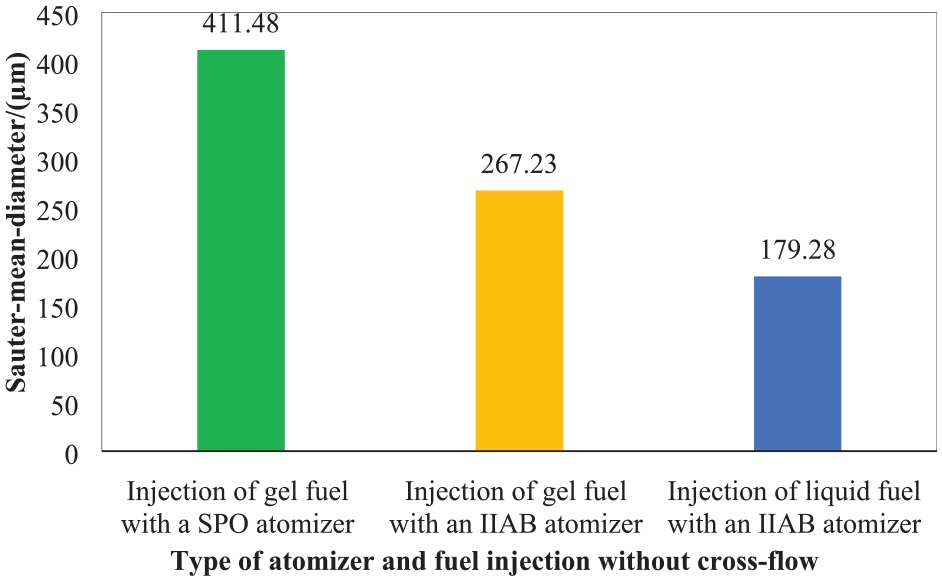
Effect of atomizers and fuels on SMD without cross-flow.
Flow physics of Jet A-1 liquid and gel fuel break-up in low-speed subsonic air cross-flow
Based on the images obtained during the investigation, an attempt has been made to describe the fuel break-up process in this section. Flow Reynold’s number is one of the vital non-dimensional parameters used to study the flow physics of the Jet A-1 liquid fuel and Jet A-1 gelled fuel using the IIAB atomizer in the cross-flow.
Break-up mechanisms of liquid fuel using an IIAB atomizer
Figure 14 depicts a typical break-up sequence of liquid jets in LSSACF. Two types of break-up mechanisms occur in liquid jets in cross-flow: one is a primary break-up mechanism, and the other one is a secondary break-up mechanism, so-called primary and secondary atomization, respectively. During the primary break-up mechanism, the liquid jet decomposes into ligaments and larger droplets. The secondary break-up mechanism, on the other hand, further disintegrated these ligaments and parent droplets into finer droplets. 4 The surface tension and aerodynamic forces dominate the physics of primary break-up, while viscosity has little effect on stability. The continuous liquid jet becomes unstable and produces jet instability because of the formation of surface waves along the liquid jet. 4 These jet instabilities can be classified as stationary or dynamic. Rayleigh or Kelvin-Helmholtz instabilities are responsible for these jet instabilities. In other words, the two primary mechanisms for droplet formation in cross-flow from the liquid jet are column and shear break-up. Surface instabilities cause the jet to disintegrate into some ligaments, resulting in the formation of parent droplets in the break-up mechanism. Droplets are formed due to shear break-up by the aerodynamic shear applied to the jet surface. 4 A typical cross-flow liquid spray break-up sequence is shown in Figure 14.
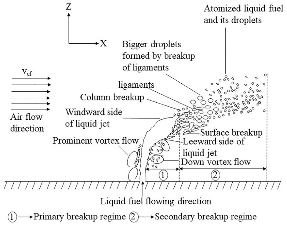
Typical break-up sequence of a liquid jet in cross-flow.
In general, the kinetic energy of the gas phase initiates the transformation of the liquid phase’s continuous medium into a discrete form of ligaments and droplets in conventional air-blast atomizers. The basic goal of this kind of air-blast atomizer design is to deploy the available air in the most efficient way to produce the best atomized liquid phase. Impinging jet atomization of liquid fuel revealed that, depending on the liquid and gas flow rates, two modes of break-up mechanism, such as classical and prompt mechanisms, occur. 47
The Jet A-1 liquid fuel is introduced by supplying pressurizing air into a constant area duct present upstream of the convergent portion of the nozzle in the IIAB atomizer. The pressurized air which enters the mixing chamber passes through the micro-air orifices present at the periphery of the convergent portion of the nozzle. These micro-air jets impinge radially on the less viscous liquid fuel. During these interactions, the liquid film is disintegrated into smaller liquid sheets and droplets inside the atomizer itself, generating primary atomization. Thereafter, on injection into the cross-flow, the liquid fuel further disintegrates into smaller droplets mainly due to aerodynamic shear causing secondary atomization. 50
Figure 15 depicts the comparative spray structure of Jet A-1 liquid and gel fuel injected transversely into the cross-flowing airstream environment using an IIAB atomizer. Both an aerodynamic force as well as the design of the atomizer influences the break-up mechanism of both fuels. Atomization of Jet A-1 liquid fuel using the IIAB atomizer produces a smaller liquid sheet in the core region and a larger spray of finer droplets in their outer edge, as is observed in Figure 15(a). This indicates that the primary break-up of the liquid jet starts inside the atomizer itself. This smaller liquid sheet and atomized liquid droplets are further disintegrated into finer droplets outside the atomizer, because of the aerodynamic force generated by the cross-flowing airstream of different cross-flow air velocities. Liquid fuel promptly breaks up when it interacts with the cross-flowing air in the exit orifice’s immediate vicinity, which is observed in Figure 15(a). It is also observed that there is a formation of twisting airflow inside the liquid spray, which is also responsible for this prompt break-up mechanism of liquid fuel.
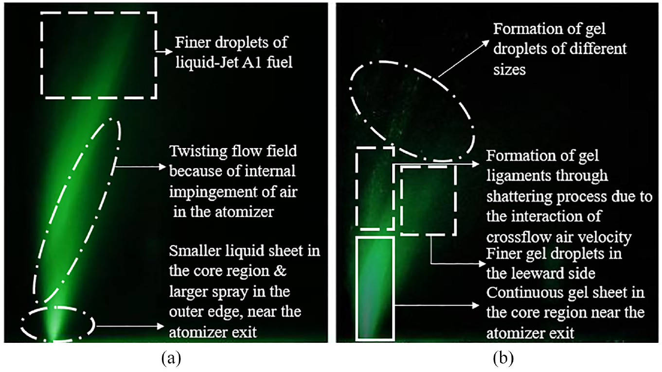
Structure of Jet A-1 liquid and gel fuel injected transversely into LSSACF: (a)
Break-up mechanisms of gel fuel using an IIAB atomizer
Externally impinging jet atomization of gel fuel begins with the formation of a thin sheet, then ligaments, and finally, droplets of varying sizes from multiple ligament break-up events. At very low jet velocities, a leaf-shaped sheet appears, and at higher jet velocities, impact wave and sheetless atomization occur. 41 Atomization of gel fuel for an IIAB atomizer begins with the formation of some disintegrated ligaments outside the atomizer, especially in low cross-flow air mass flow rate, which is followed by the formation of gel droplets of various sizes from multimode break-up modes in the ligaments. Because of the design and type of atomizer used for this investigation, the primary atomization of the gel sheet into some fragmented ligaments takes place inside the atomizer.
Atomization of gel fuel injected into cross-flow using the IIAB atomizer begins with the formation of continuous gel sheets in the core region near the atomizers exit plane, followed by the formation of gel ligaments, gel droplets of different sizes and finally, the finer gel droplets. The soft gel sheets emanating from the atomizer exit plane near the core region are disintegrated to form the gel ligaments in the windward side of the gel spray, as is observed in Figure 15(b). The formation of ligaments indicates the initial break-up of the gel within the atomizer body itself triggered by the reduction of the viscoelastic nature of gel fuel and softening of the gel sheets. The gel ligaments are further disintegrated because of the interaction of cross-flow air. Multiple ligament break-up events occur to generate gel droplets of various sizes, which is also observed in Figure 15(b). The formation of finer droplets is observed at the outer edge of the spray as well as in both the outer peripheries of the windward and leeward sides of the gelled fuel near the atomizer exit plane. These finer gel droplet formation in both the peripheries near the atomizer exit plane with sheetless atomization of the gel fuel is due to the design and type of atomizer which is used for this study. Aerodynamic waves observed in the liquid atomization process earlier may be the source of the break-up of gel ligaments.1,42 This break-up event in the gel ligaments is due to the aerodynamic wave instability in the windward side of the gel spray.
Spray structure of Jet A-1 liquid and gel fuel at various cross-flow conditions
Table 3 presents the comparison of the visualization of Jet A-1 liquid and Jet A-1 gel fuel injection at different cross-flow air mass flow rates of
Visualization of Jet A-1 liquid and Jet A-1 gel fuel at different cross-flow air mass flow rates.
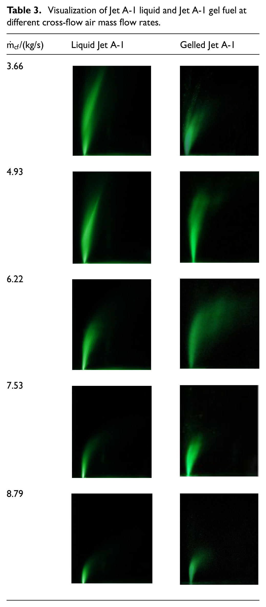
A fuel having higher viscosity (Jet A-1 gel fuel) penetrates low as compared to fuel having low viscosity (Jet A-1 liquid fuel). Highly viscous gel fuel is extremely shear dependent, and it is very difficult to flow; that’s why the penetration of the gel fuel seems to be lower for the pertinent cross-flow Reynolds’ number. Inversely, at higher
Effect of cross-flow air mass flow rate on relative droplet size distribution
Fuel atomization and droplet formation play a major role in the combustion efficiency of an aero-engine. Furthermore, droplet size dispersion within a spray is a crucial factor to consider when calculating spray fineness. 47 Large droplets in the spray are more common due to poor atomization, greater viscosity, and surface tension.
Figure 16 shows the Jet A-1 liquid and gel fuel relative droplet size distribution using an IIAB atomizer at stable ALIPR of 0.5 for miscellaneous
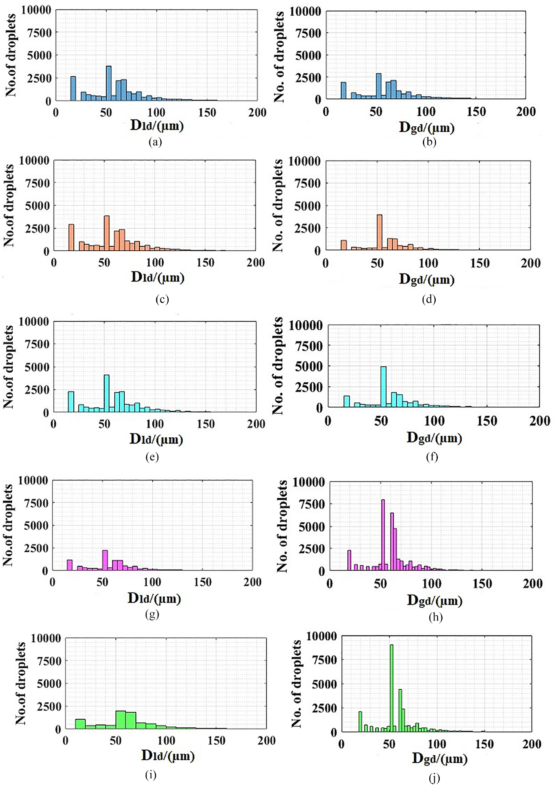
Jet A-1 liquid and gel fuel relative droplet size distribution at different
Lesser evaporation rate of liquid fuel leads to a greater number of liquid droplets at this low cross-flow air mass flow rate. But at higher cross-flow air mass flow rates, the total number of liquid droplets count significantly reduces. At higher cross-flow air mass flow rate, say,
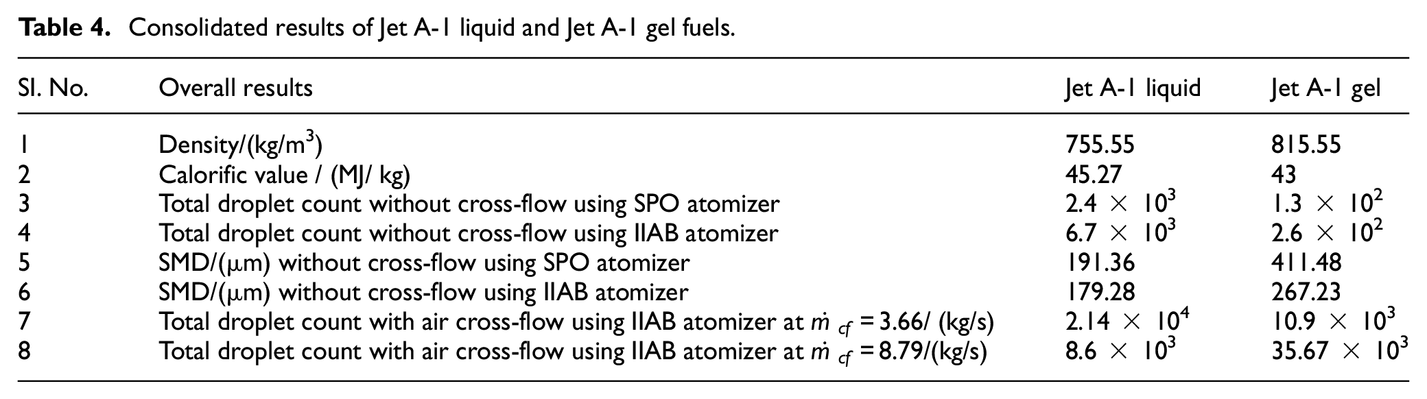
Overall results of liquid and gelled JetA-1 fuels
Table 4 provides consolidated quantitative information on the comparative results of liquid and gelled JetA-1 fuels.
Consolidated results of Jet A-1 liquid and Jet A-1 gel fuels.
Conclusion
An experimental study on the effect of atomizers and cross-flows of Jet A-1 liquid and Jet A-1 gel fuels revealed the fluidity nature and spray formation of both fuels. Comparison of both the liquid and gel fuel in terms of compactness and sprayability at varied cross-flow conditions were investigated during the study. From the results obtained, the following conclusions can be derived.
1. Density of the gel fuel prepared with a gellant concentration of 7.5% by weight is 815.55 kg/m3, which is 7.9 % higher than Jet A-1 liquid fuel density. This indicates higher compactness for the Jet A-1 gel fuel. This increase in gel density reduces the fuel tank volume, reducing the overall structural weight of the aircraft. In other words, replacing the existing liquid fuel with gel fuel achieves the design thrust of an aircraft with a small fuel tank.
2. The results obtained from the bomb calorimeter experiment agree well with the existing calorific value results of other aviation gas turbine fuels. The obtained calorific values of gelled Jet A-1 and liquid Jet A-1 fuel are 43 and 45.27 MJ/kg, respectively. It is concluded that the average calorific value of gelled Jet A-1 fuel is 2.2% less than the average calorific value of liquid Jet A-1 fuel. For superior safety reasons, gelled Jet A-1 fuel may be used in the aircraft industry. Gel fuels, in general, tend to reduce accidents during storage and spills because of their visco-elastic properties. Based on the density study, the gelled Jet A-1 fuel is found to be more compact. It is suggested that finding the most suitable metal additives will improve the gel fuel’s calorific value and density impulse, which helps to improve efficiency.
3. Primary atomization of gel fuel occurs inside the IIAB atomizer itself, and secondary atomization takes place outside the atomizer because of the interaction of air cross-flow. Relative droplet size distribution of Jet A-1 gel fuel using an SPO atomizer and Jet A-1 gel fuel using an IIAB atomizer revealed that larger number of droplets are formed using the IIAB atomizer. Thus, the atomization of gel fuels depends not only on the environment in which it is atomized but also on the type of atomizer used for the atomization process.
4. Visualization of atomization of liquid Jet A-1 fuel in cross-flow using an internally impinging atomizer revealed the dominance of prompt break-up mechanism. These findings contradict previous literature findings of both classical and prompt break-up of a liquid jet in an externally impinging air-blast atomizer.
5. For gelled Jet A-1 fuel, a combination of both sheet break-up and prompt break-up mechanisms was observed when the gel fuel was transversely injected into a low-speed subsonic air cross-flow using the IIAB atomizer. These results are in contrast to the earlier existing literature results of sheet break-up in an externally impinging atomizer and prompt break-up in an internally impinging atomizer for gel fuels.
6. Relative droplet size distribution of liquid and gelled Jet A-1 fuel showed that a smaller number of liquid droplets is present in higher cross-flow air mass flow rate as compared to gel droplets. This indicates the evaporation of liquid fuel taking place quickly at higher mass flow rates.
7. Based on the overall results obtained, the IIAB atomizer is much better than a conventional SPO atomizer in terms of the atomization of the gel fuel. Hence, it is suggested that an IIAB atomizer can be suitable for aero-combustor and propulsion system applications.
8. Finally, one can conclude that the break-up mechanism of liquid and gel fuel not only depends on the cross-flow air velocity but is also a function of the type of atomizer which is used during the atomization process.
Footnotes
Appendix
Acknowledgements
The authors thank Functionally graded laboratory from the School of Chemical & Biotechnology and the Thermal Engineering Laboratory from the School of Mechanical Engineering for their support.
Declaration of conflicting interests
The author(s) declared no potential conflicts of interest with respect to the research, authorship, and/or publication of this article.
Funding
The author(s) received no financial support for the research, authorship, and/or publication of this article.